
Aspire 1500 Service Guide
Page 7
... 30 Main 31 Advanced 33 Security 35 Boot 39 Exit 40 BIOS Flash Utility 41 Chapter 3 Machine Disassembly and Replacement 42 General Information 43 Before You Begin 43 Disassembly Procedure Flowchart 44 Removing the Battery 46 Removing the Memory Module 47 Removing the Modem Board 48 Removing ...the Hard Disk Drive Module 49 Removing the LCD Module 50 Disassembling the LCD Module 53 Disassembling the Main Unit 57 System Upgrade Procedure 67 Assembling the Main Unit 68 Assembling the LCD Module 77 Installing the LCD...
... 30 Main 31 Advanced 33 Security 35 Boot 39 Exit 40 BIOS Flash Utility 41 Chapter 3 Machine Disassembly and Replacement 42 General Information 43 Before You Begin 43 Disassembly Procedure Flowchart 44 Removing the Battery 46 Removing the Memory Module 47 Removing the Modem Board 48 Removing ...the Hard Disk Drive Module 49 Removing the LCD Module 50 Disassembling the LCD Module 53 Disassembling the Main Unit 57 System Upgrade Procedure 67 Assembling the Main Unit 68 Assembling the LCD Module 77 Installing the LCD...

Aspire 1500 Service Guide
Page 51
... T Flat-bladed screw driver T Phillips screw driver T Tweezers T Plastic Flat-bladed screw driver T Hexed Screw Driver NOTE: The screws for maintenance and troubleshooting. Chapter 3 Machine Disassembly and Replacement This chapter contains step-by-step procedures on how to avoid mismatch when putting back the components. Chapter 3 42 During the...
... T Flat-bladed screw driver T Phillips screw driver T Tweezers T Plastic Flat-bladed screw driver T Hexed Screw Driver NOTE: The screws for maintenance and troubleshooting. Chapter 3 Machine Disassembly and Replacement This chapter contains step-by-step procedures on how to avoid mismatch when putting back the components. Chapter 3 42 During the...
Aspire 1500 Service Guide
Page 52
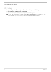
Unplug the AC adapter and all peripherals. 2. Turn off the power to tear the tape or mylar before you do the following: 1. General Information Before You Begin Before proceeding with the disassembly procedure, make sure that you disconnect different FFC/FPC/connectors. 43 Chapter 3 NOTE: Aspire 1500 series product uses mylar or tape to fasten the FFC/FPC/connectors/cable, you may need to the system and all power and signal cables from the system .
Unplug the AC adapter and all peripherals. 2. Turn off the power to tear the tape or mylar before you do the following: 1. General Information Before You Begin Before proceeding with the disassembly procedure, make sure that you disconnect different FFC/FPC/connectors. 43 Chapter 3 NOTE: Aspire 1500 series product uses mylar or tape to fasten the FFC/FPC/connectors/cable, you may need to the system and all power and signal cables from the system .
Aspire 1500 Service Guide
Page 53
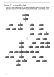
For example, if you want to remove the main board, you on the entire disassembly sequence and instructs you must first remove the keyboard, then disassemble the inside assembly frame in that need to be removed during servicing. Start Battery HDD Module *2 HDD HDD Holder *2 Dimm Cover Memory *1 ... *2 ODD Bracket ODD *4 Main Board Touchpad Touchpad Scroll Key *2 DC Board *2 Speaker Set *4 PCMCIA Slot Touchpad Cable Upper Case Chapter 3 44 Disassembly Procedure Flowchart The flowchart on the succeeding page gives you a graphic representation on the components that order.
For example, if you want to remove the main board, you on the entire disassembly sequence and instructs you must first remove the keyboard, then disassemble the inside assembly frame in that need to be removed during servicing. Start Battery HDD Module *2 HDD HDD Holder *2 Dimm Cover Memory *1 ... *2 ODD Bracket ODD *4 Main Board Touchpad Touchpad Scroll Key *2 DC Board *2 Speaker Set *4 PCMCIA Slot Touchpad Cable Upper Case Chapter 3 44 Disassembly Procedure Flowchart The flowchart on the succeeding page gives you a graphic representation on the components that order.

Aspire 1500 Service Guide
Page 58
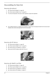
Then take the hard disk drive out of the main unit. To remove the hard disk drive, pull the hard disk dirve carefully. 3. Remove the two screws that fasten the HDD holder. 4. Detach the hard disk drive from the HDD holder. 49 Chapter 3 See "Removing the Hard Disk Drive Module" on page 46.. 2. Disassembling the Hard Disk Drive Module 1. See "Removing the Battery" on page 49.. 3. See "Removing the Battery" on page 46.. 2. Removing the Hard Disk Drive Module 1.
Then take the hard disk drive out of the main unit. To remove the hard disk drive, pull the hard disk dirve carefully. 3. Remove the two screws that fasten the HDD holder. 4. Detach the hard disk drive from the HDD holder. 49 Chapter 3 See "Removing the Hard Disk Drive Module" on page 46.. 2. Disassembling the Hard Disk Drive Module 1. See "Removing the Battery" on page 49.. 3. See "Removing the Battery" on page 46.. 2. Removing the Hard Disk Drive Module 1.

Aspire 1500 Service Guide
Page 62
... Board (15" LCD) 1. Disconnect the LCD power cable then disconnect the inverter cable from the inverter board. 7. See "Removing the Launch Board" on page 46.. 2. Disassembling the LCD Module Removing the LCD Bezel 1. Use plastic tweezers to remove the four screw pads, and then remove the four screws that fasten the...
... Board (15" LCD) 1. Disconnect the LCD power cable then disconnect the inverter cable from the inverter board. 7. See "Removing the Launch Board" on page 46.. 2. Disassembling the LCD Module Removing the LCD Bezel 1. Use plastic tweezers to remove the four screw pads, and then remove the four screws that fasten the...
Aspire 1500 Service Guide
Page 66
..... 3. See "Removing the Middle Cover" on page 50.. 3. See "Removing the RTC Battery" on page 46.. 2. See "Removing the Battery" on page 57.. 57 Chapter 3 Disassembling the Main Unit Removing the Keyboard 1. See "Removing the Battery" on page 46.. 2.
..... 3. See "Removing the Middle Cover" on page 50.. 3. See "Removing the RTC Battery" on page 46.. 2. See "Removing the Battery" on page 57.. 57 Chapter 3 Disassembling the Main Unit Removing the Keyboard 1. See "Removing the Battery" on page 46.. 2.

Aspire 1500 Service Guide
Page 97
...chapter's instructions. there are properly connected and secured; Use the following : power cords are no obviously burned or heated components; Other symptoms (i.e. Disassemble and assemble the unit without any problem occurs, you fellow this model. LCD display problems or others). Verify the symptoms by attempting to "... the same operation. 3. POST detects an error and displayed messages on page 104 Chapter 4 88 all components appear normal. 5. Non-Acer products, prototype cards, or modified options can give false errors and invalid system responses. 1.
...chapter's instructions. there are properly connected and secured; Use the following : power cords are no obviously burned or heated components; Other symptoms (i.e. Disassemble and assemble the unit without any problem occurs, you fellow this model. LCD display problems or others). Verify the symptoms by attempting to "... the same operation. 3. POST detects an error and displayed messages on page 104 Chapter 4 88 all components appear normal. 5. Non-Acer products, prototype cards, or modified options can give false errors and invalid system responses. 1.
Aspire 1500 Service Guide
Page 135
... Core logic 18 CPU core voltage 18 I/O voltage 18 Index Index package 18 type 18 D DC-AC LCD Inverter 23 DIMM Combinations 19 Disassembly Battery Pack 45 Procedure Flowchart 44 Display 2 display hotkeys 15 Display Standby Mode 25 E Environmental Requirements 25 Error Symptom-to-Spare Part Index ...Features 1 Flash Utility 41 Floppy Disk Drive Interface 20 FRU (Field Replaceable Unit) List 108 H Hard disk 18, 20 Hard Disk Drive Module Disassembly 49 Hard Disk Standby Mode 25 Hardware Specifications and Configurations 18 HDD 18, 20 Hibernation Mode 25 Hibernation mode hotkey 15 Hot Keys 15 I ...
... Core logic 18 CPU core voltage 18 I/O voltage 18 Index Index package 18 type 18 D DC-AC LCD Inverter 23 DIMM Combinations 19 Disassembly Battery Pack 45 Procedure Flowchart 44 Display 2 display hotkeys 15 Display Standby Mode 25 E Environmental Requirements 25 Error Symptom-to-Spare Part Index ...Features 1 Flash Utility 41 Floppy Disk Drive Interface 20 FRU (Field Replaceable Unit) List 108 H Hard disk 18, 20 Hard Disk Drive Module Disassembly 49 Hard Disk Standby Mode 25 Hardware Specifications and Configurations 18 HDD 18, 20 Hibernation Mode 25 Hibernation mode hotkey 15 Hot Keys 15 I ...


