
User Manual
Page 6
... batteries according to regulations applicable to a qualified service technician. 13 Warning! f If the product exhibits a distinct change in fire. Do not disassemble or dispose of power supply cord set (provided in damage and will often require extensive work by a qualified technician to restore the product to rain or water. Refer battery replacement...
... batteries according to regulations applicable to a qualified service technician. 13 Warning! f If the product exhibits a distinct change in fire. Do not disassemble or dispose of power supply cord set (provided in damage and will often require extensive work by a qualified technician to restore the product to rain or water. Refer battery replacement...

User Manual
Page 8
... the system memory Installing an expansion card Installing the TPM module Installing the System Fan module Installing a redundant power supply module 4 System BIOS BIOS overview Entering BIOS setup BIOS setup primary menus BIOS setup navigation keys Main menu... Configuration Advanced Memory Configuration Advanced Chipset Control PCI Configuration SATA Configuration I/O Device Configuration Boot Configuration Thermal and Acoustic Configuration Power Security menu Setting a system password Changing a system password Removing a system password Server menu System Management Console Redirection ...
... the system memory Installing an expansion card Installing the TPM module Installing the System Fan module Installing a redundant power supply module 4 System BIOS BIOS overview Entering BIOS setup BIOS setup primary menus BIOS setup navigation keys Main menu... Configuration Advanced Memory Configuration Advanced Chipset Control PCI Configuration SATA Configuration I/O Device Configuration Boot Configuration Thermal and Acoustic Configuration Power Security menu Setting a system password Changing a system password Removing a system password Server menu System Management Console Redirection ...

User Manual
Page 15
...45) • Fast Ethernet (RJ-45) port dedicated for BMC for management Power supply and system fan • 600 W (85% power efficiency) or 610 W power supply, 110-127 / 200-240V (can be upgraded with second power module for hotswap and redundancy) • One system fan (can be upgraded ...alert • Lockable door • IPMI 2.0 • TPM v1.2 • Built-in Altos eXpress Console for server management and KVM over IP remote management • Acer EasyBUILD™v9.0 • Acer Server Manager (ASM) Operating system • Microsoft® Windows® Server 2008 Standard and ...
...45) • Fast Ethernet (RJ-45) port dedicated for BMC for management Power supply and system fan • 600 W (85% power efficiency) or 610 W power supply, 110-127 / 200-240V (can be upgraded with second power module for hotswap and redundancy) • One system fan (can be upgraded ...alert • Lockable door • IPMI 2.0 • TPM v1.2 • Built-in Altos eXpress Console for server management and KVM over IP remote management • Acer EasyBUILD™v9.0 • Acer Server Manager (ASM) Operating system • Microsoft® Windows® Server 2008 Standard and ...

User Manual
Page 23
Power supply module fault indicator Indicates the occurrence of a fault condition in the power supply module. (green/amber) Power supply module status indicator Indicates the status of the power supply module. (green) Main power Provides the system's main power supply module supply. Power supply module cord socket Connect the system power cord here. Icon 1 2 3 4 5 Component Description Power supply module release latch Push down the latch to disengage the module from the chassis. 13 Rear panel No.
Power supply module fault indicator Indicates the occurrence of a fault condition in the power supply module. (green/amber) Power supply module status indicator Indicates the status of the power supply module. (green) Main power Provides the system's main power supply module supply. Power supply module cord socket Connect the system power cord here. Icon 1 2 3 4 5 Component Description Power supply module release latch Push down the latch to disengage the module from the chassis. 13 Rear panel No.

User Manual
Page 24
... management. Lid switch Sent out warning alerts when the lid is opened or compromised. System fan Regulates the system airflow. Redundant power supply module bay Accommodates an optional hot-swap redundant power supply module. Serial port Connects to an Internet or intranet network. Gigabit LAN ports 1/2 Connects to serial devices. USB 2.0 ports Connects to...
... management. Lid switch Sent out warning alerts when the lid is opened or compromised. System fan Regulates the system airflow. Redundant power supply module bay Accommodates an optional hot-swap redundant power supply module. Serial port Connects to an Internet or intranet network. Gigabit LAN ports 1/2 Connects to serial devices. USB 2.0 ports Connects to...

User Manual
Page 25
Component 1 Redundant power supply module bay 2 Air duct 3 Heat sink fan (HSF) assemblies 4 Sliders for the 5.25-inch devices 5 Release sliders for the HDD cages 6 Mainboard 7 PCI slot lock 8 System fan Users have the option to purchase a redundant system fan unit. 15 Internal components No.
Component 1 Redundant power supply module bay 2 Air duct 3 Heat sink fan (HSF) assemblies 4 Sliders for the 5.25-inch devices 5 Release sliders for the HDD cages 6 Mainboard 7 PCI slot lock 8 System fan Users have the option to purchase a redundant system fan unit. 15 Internal components No.

User Manual
Page 35
...% duty cycle) OFF ON Blink OFF OFF ON System Ready / No Alarm System Ready but degraded some CPU fault, DIMM killed Critical Alarm (Critical power modules, Voltage Power supply, critical temperature and voltage ... etc. failure) Non-critical Alarm (Noncritical temperature and voltage) System not ready (Post error/NMI event/CPU or terminator missing...
...% duty cycle) OFF ON Blink OFF OFF ON System Ready / No Alarm System Ready but degraded some CPU fault, DIMM killed Critical Alarm (Critical power modules, Voltage Power supply, critical temperature and voltage ... etc. failure) Non-critical Alarm (Noncritical temperature and voltage) System not ready (Post error/NMI event/CPU or terminator missing...

User Manual
Page 102
...second module to deal with equipment capable of personal injury from hot surfaces, observe the thermal labels on each power supply modules. WARNING! WARNING! Electrostatic discharge can also consider wearing protective gloves. To reduce the risk of personal ...not open the power supply module. The system ships out with a redundant power source. Caution! WARNING! There are properly grounded before handling a power supply module. 92 3 System upgrade Installing a redundant power supply module The Altos G540 M2 supports two 610-watts hot-swap power supply modules. You can...
...second module to deal with equipment capable of personal injury from hot surfaces, observe the thermal labels on each power supply modules. WARNING! WARNING! Electrostatic discharge can also consider wearing protective gloves. To reduce the risk of personal ...not open the power supply module. The system ships out with a redundant power source. Caution! WARNING! There are properly grounded before handling a power supply module. 92 3 System upgrade Installing a redundant power supply module The Altos G540 M2 supports two 610-watts hot-swap power supply modules. You can...

User Manual
Page 103
Keep the cover for future reassembly. 93 To install a hot-swap power supply module: 1 Detach the cover from the chassis.
Keep the cover for future reassembly. 93 To install a hot-swap power supply module: 1 Detach the cover from the chassis.

User Manual
Page 104
94 3 System upgrade 2 Slide the module into the empty bay until you feel resistance, and it locks into place. 3 Verify that the power status indicators on the main power supply and on the newly installed redundant power supply are illuminated green.
94 3 System upgrade 2 Slide the module into the empty bay until you feel resistance, and it locks into place. 3 Verify that the power status indicators on the main power supply and on the newly installed redundant power supply are illuminated green.

User Manual
Page 147
139 Initial troubleshooting checklist Use the checklist below to turn the server on (power on add-in boards and peripheral devices correct? and connected to a NEMA 5-15R outlet for 100-120 V or a NEMA 6-15R outlet for 200-240 V? • ... to eliminate the possible cause for the problem you're encountering. • AC power is available at the wall outlet? • Is the power supply module properly installed? • Is the system power cord properly plugged into the power supply module socket? To check these settings, refer to the operating system documentation. • Are all switch...
139 Initial troubleshooting checklist Use the checklist below to turn the server on (power on add-in boards and peripheral devices correct? and connected to a NEMA 5-15R outlet for 100-120 V or a NEMA 6-15R outlet for 200-240 V? • ... to eliminate the possible cause for the problem you're encountering. • AC power is available at the wall outlet? • Is the power supply module properly installed? • Is the system power cord properly plugged into the power supply module socket? To check these settings, refer to the operating system documentation. • Are all switch...

User Manual
Page 148
... drive, make sure there is no diskette in floppy drive and no disc in the DVD-ROM drive. 8 If the power indicator is plugged into a properly grounded AC outlet and in the power supply module cord socket. 4 Make sure the display monitor and keyboard are correctly connected to the system. 5 Turn on the...
... drive, make sure there is no diskette in floppy drive and no disc in the DVD-ROM drive. 8 If the power indicator is plugged into a properly grounded AC outlet and in the power supply module cord socket. 4 Make sure the display monitor and keyboard are correctly connected to the system. 5 Turn on the...
User Manual
Page 150
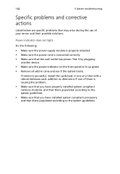
...8226; Make sure the power supply module is properly installed. • Make sure the power cord is connected correctly. • Make sure that there populated according to the system guidelines. Power indicator does not light. Test it by plugging another device. • Make sure the power indicator on the front ...there populated according to the system guidelines. • Make sure that you have installed system compliant processors, and that the wall outlet has power. If reboot is lit up green. • Remove all add-in one at a time with a reboot between each addition to determine...
...8226; Make sure the power supply module is properly installed. • Make sure the power cord is connected correctly. • Make sure that there populated according to the system guidelines. Power indicator does not light. Test it by plugging another device. • Make sure the power indicator on the front ...there populated according to the system guidelines. • Make sure that you have installed system compliant processors, and that the wall outlet has power. If reboot is lit up green. • Remove all add-in one at a time with a reboot between each addition to determine...

User Manual
Page 193
Sensor Readings The Sensor Readings option allows you to the server's health, such as the sensor reading and the event log. 185 Server Health The Server Health menu displays data related to monitor status of the voltages of the power supply, the fan speed, and the processor and system temperature sensors. This menu include two options: Sensor Readings and Event Log.
Sensor Readings The Sensor Readings option allows you to the server's health, such as the sensor reading and the event log. 185 Server Health The Server Health menu displays data related to monitor status of the voltages of the power supply, the fan speed, and the processor and system temperature sensors. This menu include two options: Sensor Readings and Event Log.

User Manual
Page 220
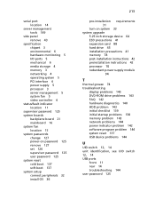
... 133 button, location 11 cable socket 13 indicator, location 11 indicator, status 24 troubleshooting 142 turn off 38 turn on 33 power off via hardware 38 via software 38 power supply module fault indicator, location 13 install 94 redundant bay 15 release latch 13 status indicator, location 13... power-on password 125 power-on self-test, see POST 34 processor BIOS settings 104 configuration guidelines 70 remove 72 upgrade 70 PS/2 keyboard port ...
... 133 button, location 11 cable socket 13 indicator, location 11 indicator, status 24 troubleshooting 142 turn off 38 turn on 33 power off via hardware 38 via software 38 power supply module fault indicator, location 13 install 94 redundant bay 15 release latch 13 status indicator, location 13... power-on password 125 power-on self-test, see POST 34 processor BIOS settings 104 configuration guidelines 70 remove 72 upgrade 70 PS/2 keyboard port ...
User Manual
Page 221
...specification chipset 3 environmental 6 hardware monitoring 5 I/O ports 5 mechanical 6 media storage 4 memory 3 networking 4 operating system 5 PCI interface 4 power supply 5 processor 3 server management 5 system fan 5 video controller 4 status/fault indicator location 11 supervisor password 125 system boards backplane board 21 ... hard drive 45 installation precautions 41 memory 78 post-installation instructions 42 preinstallation instructions 42 processor 70 redundant power supply module 94 T thermal grease 74 troubleshooting display problems 145 DVD-ROM drive problems 143 FAQ 142 hardware...
...specification chipset 3 environmental 6 hardware monitoring 5 I/O ports 5 mechanical 6 media storage 4 memory 3 networking 4 operating system 5 PCI interface 4 power supply 5 processor 3 server management 5 system fan 5 video controller 4 status/fault indicator location 11 supervisor password 125 system boards backplane board 21 ... hard drive 45 installation precautions 41 memory 78 post-installation instructions 42 preinstallation instructions 42 processor 70 redundant power supply module 94 T thermal grease 74 troubleshooting display problems 145 DVD-ROM drive problems 143 FAQ 142 hardware...

