User Manual
Page 2
...trademarks are registered trademarks of this publication may be made periodically to their respective companies. No part of Acer Inc. Acer Altos G540 M2 Series Model Name : G540 M2 Part Number: MU.R3500.001 Purchase Date: Place of merchantability or fitness for identification purposes only and belong... number are recorded on the label affixed to the contents hereof and specifically disclaims the implied warranties of Purchase: Acer and the Acer logo are used herein for a particular purpose. Acer Altos G540 M2 Series User's Guide Changes may be incorporated in new editions of this...
...trademarks are registered trademarks of this publication may be made periodically to their respective companies. No part of Acer Inc. Acer Altos G540 M2 Series Model Name : G540 M2 Part Number: MU.R3500.001 Purchase Date: Place of merchantability or fitness for identification purposes only and belong... number are recorded on the label affixed to the contents hereof and specifically disclaims the implied warranties of Purchase: Acer and the Acer logo are used herein for a particular purpose. Acer Altos G540 M2 Series User's Guide Changes may be incorporated in new editions of this...
User Manual
Page 7
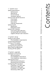
Contents 1 System tour 1 System specifications 3 Performance 3 Mechanical 6 Environmental 6 Hardware options 7 External and internal structure 9 Front bezel 9 Front panel 10 Rear panel 13 Internal components 15 System boards 16 Mainboard 16 ...
Contents 1 System tour 1 System specifications 3 Performance 3 Mechanical 6 Environmental 6 Hardware options 7 External and internal structure 9 Front bezel 9 Front panel 10 Rear panel 13 Internal components 15 System boards 16 Mainboard 16 ...

User Manual
Page 9
ix Verifying the condition of the storage devices 141 Confirming loading of the operating system 141 Specific problems and corrective actions 142 Appendix A: Server management tools 147 Server management overview 149 RAID configuration utilities 150 Onboard... management PC Installing the Java Tool Installing the UPnP tool Using the UPnP tool to search for an Altos server Altos eXpress Console Accessing the Altos eXpress Console Altos eXpress Console User Interface System Status System Information Server Health Configuration Remote Control Maintenance KVM Remote Console Utility ...
ix Verifying the condition of the storage devices 141 Confirming loading of the operating system 141 Specific problems and corrective actions 142 Appendix A: Server management tools 147 Server management overview 149 RAID configuration utilities 150 Onboard... management PC Installing the Java Tool Installing the UPnP tool Using the UPnP tool to search for an Altos server Altos eXpress Console Accessing the Altos eXpress Console Altos eXpress Console User Interface System Status System Information Server Health Configuration Remote Control Maintenance KVM Remote Console Utility ...

User Manual
Page 13
... availability) registered DIMMs for up to 96 GB of total system memory, or 1 to 4 GB unbuffered DIMMs for up to 48 GB of the Altos G540 M2 system. 3 System specifications This section lists down the impressive computing features of total system memory • Memory mirroring, Lockstep mode, x4/x8 SDDC 1 For more information on...
... availability) registered DIMMs for up to 96 GB of total system memory, or 1 to 4 GB unbuffered DIMMs for up to 48 GB of the Altos G540 M2 system. 3 System specifications This section lists down the impressive computing features of total system memory • Memory mirroring, Lockstep mode, x4/x8 SDDC 1 For more information on...

User Manual
Page 42
32 2 System setup Connecting peripherals The color-coded I/O port panel on how to configure the network setup. The server is designed to the figure below for specific connection instructions for information on the system rear accepts a variety of compatible peripherals. Note: Consult the operating system manual for each port. Caution: Do not route the power cord where it will walked on or pinched by items placed against it. Refer to be electrically grounded (earthed). To ensure proper operation, plug the power cord into a properly grounded AC outlet only.
32 2 System setup Connecting peripherals The color-coded I/O port panel on how to configure the network setup. The server is designed to the figure below for specific connection instructions for information on the system rear accepts a variety of compatible peripherals. Note: Consult the operating system manual for each port. Caution: Do not route the power cord where it will walked on or pinched by items placed against it. Refer to be electrically grounded (earthed). To ensure proper operation, plug the power cord into a properly grounded AC outlet only.
User Manual
Page 78
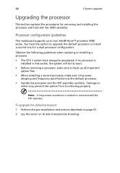
... explains the procedures for a dual-processor configuration. You have the option to boot. • Before removing a processor, make sure it has same stepping and frequency specifications as the default processor. • Handle the processor and the HSF assembly carefully. If no processor is needed to either may prevent the system from...
... explains the procedures for a dual-processor configuration. You have the option to boot. • Before removing a processor, make sure it has same stepping and frequency specifications as the default processor. • Handle the processor and the HSF assembly carefully. If no processor is needed to either may prevent the system from...

User Manual
Page 87
... on the mainboard. Independent Mode: Singel processor configuration Observe the population sequence illustrated in 1 GB, 2 GB, 4 GB, or 8 GB capacities. • Use identical modules-same specification for size, speed, and organization. Populate DIMM slots A1 first, followed by slots E1, F1, D2, E2, and F2. • To ensure data integrity, use...
... on the mainboard. Independent Mode: Singel processor configuration Observe the population sequence illustrated in 1 GB, 2 GB, 4 GB, or 8 GB capacities. • Use identical modules-same specification for size, speed, and organization. Populate DIMM slots A1 first, followed by slots E1, F1, D2, E2, and F2. • To ensure data integrity, use...

User Manual
Page 96
86 3 System upgrade Installing an expansion card This section explains how to install. 4 Install the expansion card. I/O interface Altos G540 M2 has five PCI Express® and PCI expansion slots, namely: • One PCI Express® 2.0 x16 slot • Two PCI Express® 2.0 x8 slots (with ... on page 41. 2 If necessary, remove any cables that prevent access to the processor sockets. 3 Locate an empty expansion slot that is compatible with the specification of the card you intend to install an expansion card.
86 3 System upgrade Installing an expansion card This section explains how to install. 4 Install the expansion card. I/O interface Altos G540 M2 has five PCI Express® and PCI expansion slots, namely: • One PCI Express® 2.0 x16 slot • Two PCI Express® 2.0 x8 slots (with ... on page 41. 2 If necessary, remove any cables that prevent access to the processor sockets. 3 Locate an empty expansion slot that is compatible with the specification of the card you intend to install an expansion card.

User Manual
Page 110
System Date Sets the date following the hour-minute-second format. 102 Main menu 4 System BIOS Parameter Description System Time Sets the system time following the weekday-month-day-year format. BIOS Version Version number of the BIOS setup utility BIOS Date Date when the BIOS setup utility was created CPU Type CPU Speed CPU Count Technical specifications for the installed processor Extended Memory Total size of extended memory detected during POST
System Date Sets the date following the hour-minute-second format. 102 Main menu 4 System BIOS Parameter Description System Time Sets the system time following the weekday-month-day-year format. BIOS Version Version number of the BIOS setup utility BIOS Date Date when the BIOS setup utility was created CPU Type CPU Speed CPU Count Technical specifications for the installed processor Extended Memory Total size of extended memory detected during POST

User Manual
Page 114
... enable the Intel Virtualization Technology function. See "Processor Power Management" on the next boot-up. 106 4 System BIOS Parameter Description Option Multiprocessor Sets the multiprocessor 1.1 Specifications specifications. 1.4 Intel Virtualization Technology Select whether to delete the historical processor data log. Processor(s) will be retested on page 108 for CPU Thermal Trip Set what...
... enable the Intel Virtualization Technology function. See "Processor Power Management" on the next boot-up. 106 4 System BIOS Parameter Description Option Multiprocessor Sets the multiprocessor 1.1 Specifications specifications. 1.4 Intel Virtualization Technology Select whether to delete the historical processor data log. Processor(s) will be retested on page 108 for CPU Thermal Trip Set what...

User Manual
Page 144
This chapter provides possible solutions for specific problems. If you cannot correct the problem, contact your local Acer representative or authorized dealer for assistance.
This chapter provides possible solutions for specific problems. If you cannot correct the problem, contact your local Acer representative or authorized dealer for assistance.

User Manual
Page 146
If the problem you are usually caused by an incorrect installation or configuration. 138 5 System troubleshooting Initial system startup problems Problems that occur at initial system startup are experiencing is with a specific application, see the "There is a less possible cause. Hardware failure is problem with the software program" section on page 144.
If the problem you are usually caused by an incorrect installation or configuration. 138 5 System troubleshooting Initial system startup problems Problems that occur at initial system startup are experiencing is with a specific application, see the "There is a less possible cause. Hardware failure is problem with the software program" section on page 144.

User Manual
Page 149
... the operating system prompt does not appear, see "No characters appear the display monitor" on green briefly. As each mass storage device installed in the "Specific problems and corrective actions" section. Check the activity indicators for the presence of the operating system Once the system boots up , refer to the operating...
... the operating system prompt does not appear, see "No characters appear the display monitor" on green briefly. As each mass storage device installed in the "Specific problems and corrective actions" section. Check the activity indicators for the presence of the operating system Once the system boots up , refer to the operating...
User Manual
Page 150
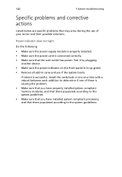
... at a time with a reboot between each addition to determine if one of your server and their possible solutions. 142 5 System troubleshooting Specific problems and corrective actions Listed below are specific problems that may arise during the use of them is causing the problem. • Make sure that you have properly installed system...
... at a time with a reboot between each addition to determine if one of your server and their possible solutions. 142 5 System troubleshooting Specific problems and corrective actions Listed below are specific problems that may arise during the use of them is causing the problem. • Make sure that you have properly installed system...

User Manual
Page 151
Do the following : • Make sure the memory modules specifications comply with the system requirements. • Make sure the memory modules have been populated according to the system guidelines. • Make sure the memory modules ...
Do the following : • Make sure the memory modules specifications comply with the system requirements. • Make sure the memory modules have been populated according to the system guidelines. • Make sure the memory modules ...

User Manual
Page 159
An array selection window displays the devices connected to the current controller. 3 Press the arrow keys to choose the specific physical drives, then press the space bar to reboot the system. The available adapter options will be displayed. 3 Press Enter in the adapter list. The ...
An array selection window displays the devices connected to the current controller. 3 Press the arrow keys to choose the specific physical drives, then press the space bar to reboot the system. The available adapter options will be displayed. 3 Press Enter in the adapter list. The ...

User Manual
Page 163
... Menu. 2 Select New Configuration from Management Menu. An array selection window displays the devices connected to the current controller. 3 Press the arrow keys to choose specific physical drives and press spacebar to reboot the server. All logical drives should be listed under Logical Drives. 2 Press Spacebar to select drives for the...
... Menu. 2 Select New Configuration from Management Menu. An array selection window displays the devices connected to the current controller. 3 Press the arrow keys to choose specific physical drives and press spacebar to reboot the server. All logical drives should be listed under Logical Drives. 2 Press Spacebar to select drives for the...

User Manual
Page 219
... drive install, easy-swap 58 install, hot-plug 55 5.25 inch device bays install 64, 66 location 10 supported devices 4 A Acer EasyBUILD scope 36 using 36 advanced memory configuration BIOS settings 110 air duct location 15 remove 84 B backplane board board layout 21 cable connections...-ROM drive location 10 troubleshooting 143 E easy-swap HDD cable connections 58, 63 install 58, 63 electrostatic discharge, see ESD precautions 41 environmental specifications temperature 6 expansion card I/O interface 88 install 88 F floppy disk drive replace 64 front bezel remove 44 view 9 front panel 10 H hard...
... drive install, easy-swap 58 install, hot-plug 55 5.25 inch device bays install 64, 66 location 10 supported devices 4 A Acer EasyBUILD scope 36 using 36 advanced memory configuration BIOS settings 110 air duct location 15 remove 84 B backplane board board layout 21 cable connections...-ROM drive location 10 troubleshooting 143 E easy-swap HDD cable connections 58, 63 install 58, 63 electrostatic discharge, see ESD precautions 41 environmental specifications temperature 6 expansion card I/O interface 88 install 88 F floppy disk drive replace 64 front bezel remove 44 view 9 front panel 10 H hard...

User Manual
Page 220
... location 14 network connection indicator 27 network speed indicator 27 troubleshooting 144 LED indicators front panel 24 HDD carrier 26 LAN port 27 M mechanical specifications chassis 6 media storage specification 4 memory install 85 population order 79 remove 83 troubleshooting 143 monitor port 14 O Onboard SATA RAID Configuration Utility 150 operating system configure 36...
... location 14 network connection indicator 27 network speed indicator 27 troubleshooting 144 LED indicators front panel 24 HDD carrier 26 LAN port 27 M mechanical specifications chassis 6 media storage specification 4 memory install 85 population order 79 remove 83 troubleshooting 143 monitor port 14 O Onboard SATA RAID Configuration Utility 150 operating system configure 36...
User Manual
Page 221
serial port location 14 server management tools 149 side panel remove 43 specification chipset 3 environmental 6 hardware monitoring 5 I/O ports 5 mechanical 6 media storage 4 memory 3 networking 4 operating system 5 PCI interface 4 power supply 5 processor 3 server management 5 system fan 5 video controller 4 status/fault ...
serial port location 14 server management tools 149 side panel remove 43 specification chipset 3 environmental 6 hardware monitoring 5 I/O ports 5 mechanical 6 media storage 4 memory 3 networking 4 operating system 5 PCI interface 4 power supply 5 processor 3 server management 5 system fan 5 video controller 4 status/fault ...