Acer Aspire One AOA150 Application Manual
Page 6
... any charger or battery that are covered by a qualified technician to restore the product to normal condition. Do not pierce, open or disassemble the battery. Accidental short-circuiting can be charged and discharged hundreds of times, but it to temperatures over 60°C (140°F).... risks. When the operation time becomes noticeably shorter than normal, buy a new battery. Do not short-circuit the battery. Use only Acer approved batteries, and recharge your pocket or purse. Unplug this product from the wall outlet and refer servicing to qualified service personnel when:...
... any charger or battery that are covered by a qualified technician to restore the product to normal condition. Do not pierce, open or disassemble the battery. Accidental short-circuiting can be charged and discharged hundreds of times, but it to temperatures over 60°C (140°F).... risks. When the operation time becomes noticeably shorter than normal, buy a new battery. Do not short-circuit the battery. Use only Acer approved batteries, and recharge your pocket or purse. Unplug this product from the wall outlet and refer servicing to qualified service personnel when:...
Acer Aspire One AOA150 Application Manual
Page 7
... the same type as that which could cause an explosion or fire resulting in a fire as they may present a risk of used batteries. Do not disassemble or dispose of them away from children. Always try to local regulations. Battery performance is especially limited in temperatures well below deck on the use...
... the same type as that which could cause an explosion or fire resulting in a fire as they may present a risk of used batteries. Do not disassemble or dispose of them away from children. Always try to local regulations. Battery performance is especially limited in temperatures well below deck on the use...
Acer Aspire One AOA150 User's Guide
Page 5
... immediately. Refer all servicing to leak acid, become hot, explode or ignite and cause injury and/or damage. Do not pierce, open or disassemble the battery. Do not put, store or leave your battery only with the supplied power supply cord set , make sure that are covered by...°C (140°F). Guidelines for service • the product does not operate normally after two or three complete charge and discharge cycles. Use only Acer approved batteries, and recharge your product in or near a heat source, in a high temperature location, in strong direct sunlight, in a microwave oven ...
... immediately. Refer all servicing to leak acid, become hot, explode or ignite and cause injury and/or damage. Do not pierce, open or disassemble the battery. Do not put, store or leave your battery only with the supplied power supply cord set , make sure that are covered by...°C (140°F). Guidelines for service • the product does not operate normally after two or three complete charge and discharge cycles. Use only Acer approved batteries, and recharge your product in or near a heat source, in a high temperature location, in strong direct sunlight, in a microwave oven ...

Acer Aspire One AOA150 User's Guide
Page 6
... below freezing. For safety reasons, do not connect the telephone line to interference from children. Do not dispose as that is fully charged. Do not disassemble or dispose of electric shock from the equipment when not in summer or winter. Follow local regulations when disposing of batteries according to keep the...
... below freezing. For safety reasons, do not connect the telephone line to interference from children. Do not dispose as that is fully charged. Do not disassemble or dispose of electric shock from the equipment when not in summer or winter. Follow local regulations when disposing of batteries according to keep the...

Aspire One 8.9-Inch Series (AOA) Application Manual English
Page 6
...the battery, charging will eventually wear out. When the operation time becomes noticeably shorter than normal, buy a new battery. Use only Acer approved batteries, and recharge your pocket or purse. The battery can occur when a metallic object such as opening or removing covers ...60°C (140°F). Failure to follow these guidelines may damage the battery or the connecting object. Do not pierce, open or disassemble the battery. Accidental short-circuiting can be charged and discharged hundreds of times, but it will not occur at temperatures below 0°C...
...the battery, charging will eventually wear out. When the operation time becomes noticeably shorter than normal, buy a new battery. Use only Acer approved batteries, and recharge your pocket or purse. The battery can occur when a metallic object such as opening or removing covers ...60°C (140°F). Failure to follow these guidelines may damage the battery or the connecting object. Do not pierce, open or disassemble the battery. Accidental short-circuiting can be charged and discharged hundreds of times, but it will not occur at temperatures below 0°C...

Aspire One 8.9-Inch Series (AOA) Application Manual English
Page 7
... fuel depots, storage and distribution areas; Always try to this equipment during lightning or thunderstorms. Warning! Batteries may explode if not handled properly. Do not disassemble or dispose of batteries according to turn off the notebook near gas pumps at service stations. Dispose of them away from the equipment when not...
... fuel depots, storage and distribution areas; Always try to this equipment during lightning or thunderstorms. Warning! Batteries may explode if not handled properly. Do not disassemble or dispose of batteries according to turn off the notebook near gas pumps at service stations. Dispose of them away from the equipment when not...
Service Guide
Page 7
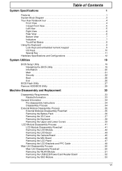
Table of Contents System Specifications 1 Features 1 System Block Diagram 3 Your Acer Notebook tour 4 Front View 4 Closed Front View 5 Left View 5 Right View 6 Rear View 6 Bottom View 7 Indicators 7 TouchPad Basics 8 Using the Keyboard 9 Lock Keys and embedded ... Removing the Battery Pack 36 Removing the 3G Cover 37 Removing the Keyboard 38 Removing the Upper and Lower Covers 39 LCD Module Disassembly Process 41 LCD Module Disassembly Flowchart 41 Removing the LCD Module 42 Removing the LCD Bezel 44 Removing the Camera Board 45 Removing the MIC Board 46 Removing...
Table of Contents System Specifications 1 Features 1 System Block Diagram 3 Your Acer Notebook tour 4 Front View 4 Closed Front View 5 Left View 5 Right View 6 Rear View 6 Bottom View 7 Indicators 7 TouchPad Basics 8 Using the Keyboard 9 Lock Keys and embedded ... Removing the Battery Pack 36 Removing the 3G Cover 37 Removing the Keyboard 38 Removing the Upper and Lower Covers 39 LCD Module Disassembly Process 41 LCD Module Disassembly Flowchart 41 Removing the LCD Module 42 Removing the LCD Bezel 44 Removing the Camera Board 45 Removing the MIC Board 46 Removing...
Service Guide
Page 43
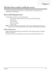
... troubleshooting. The product previews seen in size. Chapter 3 33 During the disassembly process, group the screws with the corresponding components to disassemble the notebook computer for the different components vary in the disassembly procedures may differ slightly from a SSD SKU. Related Information Please note that... were taken using the HDD SKU, unless otherwise specified, and may not represent the final product color. Machine Disassembly and Replacement Chapter 3 This chapter contains step-by-step procedures on how to avoid mismatch when putting back the components.
... troubleshooting. The product previews seen in size. Chapter 3 33 During the disassembly process, group the screws with the corresponding components to disassemble the notebook computer for the different components vary in the disassembly procedures may differ slightly from a SSD SKU. Related Information Please note that... were taken using the HDD SKU, unless otherwise specified, and may not represent the final product color. Machine Disassembly and Replacement Chapter 3 This chapter contains step-by-step procedures on how to avoid mismatch when putting back the components.

Service Guide
Page 44
... surface. 4. For example, if you want to remove the main board, you do the following sections: • Upper cover disassembly • LCD module disassembly • Main unit disassembly The flowcharts provided in that order. Observe the order of the hardware components. Main Screw List Screw Quantity Part Number M2*3 (NL... the sequence to avoid damage to the system and all power and signal cables from the system. 3. General Information Pre-disassembly Instructions Before proceeding with the disassembly procedure, make sure that you must first remove the keyboard, then...
... surface. 4. For example, if you want to remove the main board, you do the following sections: • Upper cover disassembly • LCD module disassembly • Main unit disassembly The flowcharts provided in that order. Observe the order of the hardware components. Main Screw List Screw Quantity Part Number M2*3 (NL... the sequence to avoid damage to the system and all power and signal cables from the system. 3. General Information Pre-disassembly Instructions Before proceeding with the disassembly procedure, make sure that you must first remove the keyboard, then...

Service Guide
Page 45
External Module Disassembly Process External Modules Disassembly Flowchart The flowchart below gives you a graphic representation on the entire disassembly sequence and instructs you on the components that require complete disassembly. Screw List Step Upper Cover Screw M2*5 M2*3 (NL) Quantity 5 3 Color Black Black Part No. 86.TG607.004 86.S0207.001 Chapter 3 35 Disassembly is divided into two tiers. Tier 2 incorporates the remaining FRU parts that need to be removed during servicing. Tier 1 comprises of FRU parts that do not require complete disassembly of the computer.
External Module Disassembly Process External Modules Disassembly Flowchart The flowchart below gives you a graphic representation on the entire disassembly sequence and instructs you on the components that require complete disassembly. Screw List Step Upper Cover Screw M2*5 M2*3 (NL) Quantity 5 3 Color Black Black Part No. 86.TG607.004 86.S0207.001 Chapter 3 35 Disassembly is divided into two tiers. Tier 2 incorporates the remaining FRU parts that need to be removed during servicing. Tier 1 comprises of FRU parts that do not require complete disassembly of the computer.
Service Guide
Page 60
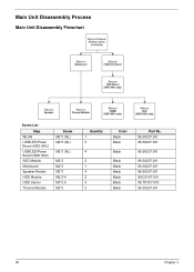
Main Unit Disassembly Process Main Unit Disassembly Flowchart Screw List Step WLAN USB/LED/Power Board (HDD SKU) USB/LED/Power Board (SSD SKU) SSD Module Mainboard Speaker Module HDD Module HDD Carrier Thermal Module Screw M2*3 (NL) M2*3 (NL) M2*3 (NL) M2*3 M2*3 M2*3 M2.5*4 M3*3.5 M2*3 Quantity 1 3 4 2 1 4 2 4 3 Color Black Black Black Black Black Black Black Black Black Part No. 86.S0207.001 86.S0207.001 86.S0207.001 86.S0207.001 86.S0207.001 86.S0207.001 86.D01V7.001 86.TDY07.003 86.S0207.001 50 Chapter 3
Main Unit Disassembly Process Main Unit Disassembly Flowchart Screw List Step WLAN USB/LED/Power Board (HDD SKU) USB/LED/Power Board (SSD SKU) SSD Module Mainboard Speaker Module HDD Module HDD Carrier Thermal Module Screw M2*3 (NL) M2*3 (NL) M2*3 (NL) M2*3 M2*3 M2*3 M2.5*4 M3*3.5 M2*3 Quantity 1 3 4 2 1 4 2 4 3 Color Black Black Black Black Black Black Black Black Black Part No. 86.S0207.001 86.S0207.001 86.S0207.001 86.S0207.001 86.S0207.001 86.S0207.001 86.D01V7.001 86.TDY07.003 86.S0207.001 50 Chapter 3
Service Guide
Page 61
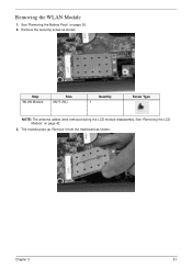
Step WLAN Module Size M2*3 (NL) Quantity 1 Screw Type NOTE: The antenna cables were removed during the LCD module disassembly. The module pops up. Removing the WLAN Module 1. See "Removing the Battery Pack" on page 42. 3. See "Removing the LCD Module" on page 36. 2. Remove it from the mainboard as shown. Chapter 3 51 Remove the securing screw as shown.
Step WLAN Module Size M2*3 (NL) Quantity 1 Screw Type NOTE: The antenna cables were removed during the LCD module disassembly. The module pops up. Removing the WLAN Module 1. See "Removing the Battery Pack" on page 42. 3. See "Removing the LCD Module" on page 36. 2. Remove it from the mainboard as shown. Chapter 3 51 Remove the securing screw as shown.
Service Guide
Page 92
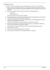
... one at least one until the failure point is done by pressing Fn+F5. If the POST or video appears on the external display, see "Disassembly Process" on page 34). 8. Reseat the memory modules. 7. Disconnect power and all external devices including port replicators or docking stations. Remove the drives (see "LCD...
... one at least one until the failure point is done by pressing Fn+F5. If the POST or video appears on the external display, see "Disassembly Process" on page 34). 8. Reseat the memory modules. 7. Disconnect power and all external devices including port replicators or docking stations. Remove the drives (see "LCD...
Service Guide
Page 93
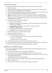
...intermittent loss of BIOS information, perform the following actions one year old, replace the CMOS battery. 2. Chapter 4 83 See "Disassembly Process" on the desktop and select Personalize´ Display Settings. Adjust the brightness to the desired resolution. Check the display ...Diagnostic from the BIOS, the drive may reduce display brightness. e. If the computer is virus free. 3. Reboot the computer. 2. See "Disassembly Process" on page 161. 10. Minimize or close all Windows. If the Issue is faulty and should be replaced. Replace the Motherboard....
...intermittent loss of BIOS information, perform the following actions one year old, replace the CMOS battery. 2. Chapter 4 83 See "Disassembly Process" on the desktop and select Personalize´ Display Settings. Adjust the brightness to the desired resolution. Check the display ...Diagnostic from the BIOS, the drive may reduce display brightness. e. If the computer is virus free. 3. Reboot the computer. 2. See "Disassembly Process" on page 161. 10. Minimize or close all Windows. If the Issue is faulty and should be replaced. Replace the Motherboard....
Service Guide
Page 98
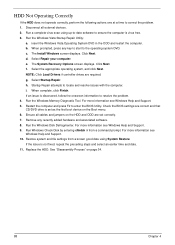
... and press F2 to locate and resolve issues with the computer. Run the Windows Disk Defragmenter. For more information see Windows Help and Support. 5. See "Disassembly Process" on the Boot menu. 6. Click Next. Select Repair your computer. Startup Repair attempts to enter the BIOS Utility. Remove any key to start to...
... and press F2 to locate and resolve issues with the computer. Run the Windows Disk Defragmenter. For more information see Windows Help and Support. 5. See "Disassembly Process" on the Boot menu. 6. Click Next. Select Repair your computer. Startup Repair attempts to enter the BIOS Utility. Remove any key to start to...


