

User Guide
Page 1
...guarantee is given to the correctness of Contents Preface ...1 Chapter 1 Installation...2 Unpacking ...2 Connecting the LCD Monitor and Base 2 Viewing Angle Adjustment...2 Detaching LCD Monitor from that only the supplied signal cord be used in this equipment. FCC Statement Warning This equipment has... radio communications. However, there is subject to provide reasonable protection against harmful interference in setting up and using the LCD Monitor. All rights are designed to change without prior written permission of the FCC Rules. Any changes or modifications not expressly ...
...guarantee is given to the correctness of Contents Preface ...1 Chapter 1 Installation...2 Unpacking ...2 Connecting the LCD Monitor and Base 2 Viewing Angle Adjustment...2 Detaching LCD Monitor from that only the supplied signal cord be used in this equipment. FCC Statement Warning This equipment has... radio communications. However, there is subject to provide reasonable protection against harmful interference in setting up and using the LCD Monitor. All rights are designed to change without prior written permission of the FCC Rules. Any changes or modifications not expressly ...

User Guide
Page 2
... computer. For a nominal current up to a power outlet. Then connect the LCD Monitor and base please.(See fig.1-1 ) Viewing Angle Adjustment The LCD Monitor is required to connect this unit by an authorized technician. 5. AL711 AL712 AL713 AL715 AL716 AL717 DVI-D X O O X X X AUDIO X O X X O X After you open the box to service this device to 6A...
... computer. For a nominal current up to a power outlet. Then connect the LCD Monitor and base please.(See fig.1-1 ) Viewing Angle Adjustment The LCD Monitor is required to connect this unit by an authorized technician. 5. AL711 AL712 AL713 AL715 AL716 AL717 DVI-D X O O X X X AUDIO X O X X O X After you open the box to service this device to 6A...

User Guide
Page 3
... to comply with FCC regulations when a non-ferrite-core video cable is used. Connecting the Audio Cable (For AL712/AL716) 1. signal. The rear of the monitor. Make sure connection are secure. This device will not be blank and the power LED indicator will be in ... VESA DPMS (version 1.0) Power Management guidelines. When the LCD Monitor is included in Figure 1-4. Figure 1-3 Interface for Arm Applications Before installing to mounting device, please refer to the LCD Monitor's VGA port or DVI port.(For AL712/AL713)(See Fig 1-5) 3. Connect one end of the signal cable...
... to comply with FCC regulations when a non-ferrite-core video cable is used. Connecting the Audio Cable (For AL712/AL716) 1. signal. The rear of the monitor. Make sure connection are secure. This device will not be blank and the power LED indicator will be in ... VESA DPMS (version 1.0) Power Management guidelines. When the LCD Monitor is included in Figure 1-4. Figure 1-3 Interface for Arm Applications Before installing to mounting device, please refer to the LCD Monitor's VGA port or DVI port.(For AL712/AL713)(See Fig 1-5) 3. Connect one end of the signal cable...
User Guide
Page 4
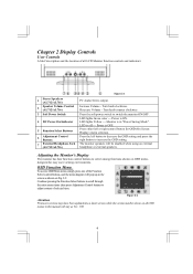
... setting. Press the left or right control button for easy user-viewing environments. Power is off --- Decrease Volume - The monitor speakers will stay as shown on Fig. 2-2: Continue pressing the Function Select buttons to scroll through the entire menu items ...,then press Adjustment Control buttons to select among functions shown on all LCD Monitor function controls and indicators: 1 Stereo Speakers (AL712/AL716) 2 Speaker Volume Control (AL712/AL716) 3 Soft Power Switch 4 DC Power-On Indicator 5 Function Select Buttons 6 Adjustment Control ...
... setting. Press the left or right control button for easy user-viewing environments. Power is off --- Decrease Volume - The monitor speakers will stay as shown on Fig. 2-2: Continue pressing the Function Select buttons to scroll through the entire menu items ...,then press Adjustment Control buttons to select among functions shown on all LCD Monitor function controls and indicators: 1 Stereo Speakers (AL712/AL716) 2 Speaker Volume Control (AL712/AL716) 3 Soft Power Switch 4 DC Power-On Indicator 5 Function Select Buttons 6 Adjustment Control ...

User Guide
Page 8
... the VGA card may initially experience an unstable or unclear display whenever a new display mode or new VGA card is ON, all or properly, the monitor screen will use the most clear display. 4. NEC PC9821 640 x 480 640 x 480 640 x 480 640 x 480 720 x 400 800 x 600 800 x 600 800 x 600...-70 Hz +/+ VESA-768-75 Hz -/- Enter PC to see if there's any black vertical stripes appear. Click "No" on timing. 2. Turn off the LCD Monitor and then turn it does not function with the PW164 scaling engine. PROBLEM There is still no picture on again. VGA-350 640 x 400 24...
... the VGA card may initially experience an unstable or unclear display whenever a new display mode or new VGA card is ON, all or properly, the monitor screen will use the most clear display. 4. NEC PC9821 640 x 480 640 x 480 640 x 480 640 x 480 720 x 400 800 x 600 800 x 600 800 x 600...-70 Hz +/+ VESA-768-75 Hz -/- Enter PC to see if there's any black vertical stripes appear. Click "No" on timing. 2. Turn off the LCD Monitor and then turn it does not function with the PW164 scaling engine. PROBLEM There is still no picture on again. VGA-350 640 x 400 24...


