AL1716e Service Guide
Page 21
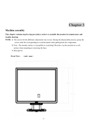
The screws for maintenance and trouble shooting NOTE : 1. Therefore, lay the monitor on how to assemble the monitor for the different components vary in size. Wear gloves. Note : The monitor surface is susceptible to avoid mismatch when putting back the components. 2. During the disassembly process, group the screws with the corresponding to scratching! Front View : ( unit : mm ) - 21 - Chapter 3 Machine assembly This chapter contains step-by-step procedures on a soft surface when mounting or removing the base. 3.
The screws for maintenance and trouble shooting NOTE : 1. Therefore, lay the monitor on how to assemble the monitor for the different components vary in size. Wear gloves. Note : The monitor surface is susceptible to avoid mismatch when putting back the components. 2. During the disassembly process, group the screws with the corresponding to scratching! Front View : ( unit : mm ) - 21 - Chapter 3 Machine assembly This chapter contains step-by-step procedures on a soft surface when mounting or removing the base. 3.

AL1716v Service Guide
Page 26
Remove four screws to assemble the monitor for maintenance. Chapter 3 Machine Disassembly This chapter contains step-by-step procedures on how to release stand base. (Fig 2) Fig 1 Fig 2 25 Remove hinge cover. (Fig 1) 2. Disassembly Procedure Disassemble the base 1.
Remove four screws to assemble the monitor for maintenance. Chapter 3 Machine Disassembly This chapter contains step-by-step procedures on how to release stand base. (Fig 2) Fig 1 Fig 2 25 Remove hinge cover. (Fig 1) 2. Disassembly Procedure Disassemble the base 1.
AL1716W Service Guide
Page 48
... way along the front bezel to release the stand base. 7115240121P0A 7740412200P0A SCREW_M4*12_DOUBLE WASHIER STAND_BASE_ACER_AL1717_#6800_ABS 94HB S6 Turn over the LCD monitor (screen faced up on the front bezel to cover page Q'ty Remark 4 Screw Size=M4x12; remove the bezel carefully. 7737517400P0A FC ASSY_#6790/#6810_ABS94V0_ACER_T17BNHW Key...working on the panel where you are release from the Front Bezel. 7140130061P0A T17BNHW-G1(99)_ACER_FUNCTION KEY BD SCREW_MACHINE_WITHOUT_NINDING_M3_6L_BLA ACER AL1716W 47 Go to - - S7 S8 Place cloth on to protect the panel.
... way along the front bezel to release the stand base. 7115240121P0A 7740412200P0A SCREW_M4*12_DOUBLE WASHIER STAND_BASE_ACER_AL1717_#6800_ABS 94HB S6 Turn over the LCD monitor (screen faced up on the front bezel to cover page Q'ty Remark 4 Screw Size=M4x12; remove the bezel carefully. 7737517400P0A FC ASSY_#6790/#6810_ABS94V0_ACER_T17BNHW Key...working on the panel where you are release from the Front Bezel. 7140130061P0A T17BNHW-G1(99)_ACER_FUNCTION KEY BD SCREW_MACHINE_WITHOUT_NINDING_M3_6L_BLA ACER AL1716W 47 Go to - - S7 S8 Place cloth on to protect the panel.
AL1716W User's Guide
Page 1
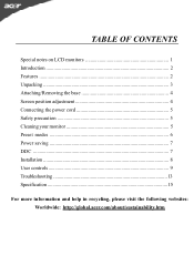
TABLE OF CONTENTS Special notes on LCD monitors 1 Introduction 2 Features ...2 Unpacking 3 Attaching/Removing the base 4 Screen position adjustment 4 Connecting the power cord 5 Safety precaution 5 Cleaning your monitor 5 Preset modes 6 Power saving 7 DDC ...7 Installation 8 User controls 9 Troubleshooting 13 Specification 15 For more information and help in recycling, please visit the following websites: Worldwide: http://global.acer.com/about/sustainability.htm
TABLE OF CONTENTS Special notes on LCD monitors 1 Introduction 2 Features ...2 Unpacking 3 Attaching/Removing the base 4 Screen position adjustment 4 Connecting the power cord 5 Safety precaution 5 Cleaning your monitor 5 Preset modes 6 Power saving 7 DDC ...7 Installation 8 User controls 9 Troubleshooting 13 Specification 15 For more information and help in recycling, please visit the following websites: Worldwide: http://global.acer.com/about/sustainability.htm
AL1716W User's Guide
Page 5
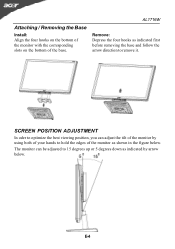
Attaching / Removing the Base Install: Align the four hooks on the bottom of the monitor with the corresponding slots on the bottom of the monitor as shown in the figure below . E-4 The monitor can adjust the tilt of your hands to remove it. AL1716W Remove: Depress the four hooks as indicated by using both of the monitor by arrow below . SCREEN POSITION ADJUSTMENT In oder to optimize the best viewing position, you can be adjusted to 15 degrees up or 5 degrees down as indicated first before removing the base and follow the arrow direction to hold the edges of the base.
Attaching / Removing the Base Install: Align the four hooks on the bottom of the monitor with the corresponding slots on the bottom of the monitor as shown in the figure below . E-4 The monitor can adjust the tilt of your hands to remove it. AL1716W Remove: Depress the four hooks as indicated by using both of the monitor by arrow below . SCREEN POSITION ADJUSTMENT In oder to optimize the best viewing position, you can be adjusted to 15 degrees up or 5 degrees down as indicated first before removing the base and follow the arrow direction to hold the edges of the base.
AL1716x Service Guide
Page 27
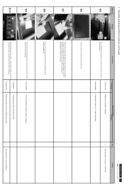
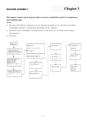
...,ZN)*4 Bracket Finger *1 Stand plate*1 Rubber*4 Hinge cover*1 Front bezel*1 Button*1 Indicator*1 27 The screws for maintenance and troubleshooting. The monitor surface is susceptible to avoid mismatch when putting back the components. 2. During the disassembly process, collect the screws with the corresponding components to scratching...! MACHINE ASSEMBLY Chapter 3 This chapter contains step-by-step procedures on a soft surface when mounting or removing the base. 3. Therefore, lay the monitor on how to assemble the monitor for the different components vary in size.
...,ZN)*4 Bracket Finger *1 Stand plate*1 Rubber*4 Hinge cover*1 Front bezel*1 Button*1 Indicator*1 27 The screws for maintenance and troubleshooting. The monitor surface is susceptible to avoid mismatch when putting back the components. 2. During the disassembly process, collect the screws with the corresponding components to scratching...! MACHINE ASSEMBLY Chapter 3 This chapter contains step-by-step procedures on a soft surface when mounting or removing the base. 3. Therefore, lay the monitor on how to assemble the monitor for the different components vary in size.


