
Intel Smart Response Installation Guide
Page 1
... the OS to use Enhanced or Maximized Mode. 6. Intel Smart Response Technology Installation Guide This motherboard supports Intel Smart Response Technology. For the new version RST driver, please check our website for the latest information: http://www.asrock.com * Before you use RST function, you want to a RAID mode system, then install...
... the OS to use Enhanced or Maximized Mode. 6. Intel Smart Response Technology Installation Guide This motherboard supports Intel Smart Response Technology. For the new version RST driver, please check our website for the latest information: http://www.asrock.com * Before you use RST function, you want to a RAID mode system, then install...
RAID Installation Guide
Page 2
You may install SATA hard disks on SATA ports. 2 This section will guide you how to create RAID on this guide carefully according to SATA Hard Disks Installation 1.1 Serial ATA (SATA) Hard Disks Installation Intel chipset supports Serial ATA (SATA) hard disks with RAID functions, including RAID 0, RAID 1, RAID 5, RAID 10 and Intel Rapid Storage. 1. Please read the RAID configurations in this motherboard for internal storage devices. Guide to the Intel southbridge chipset that your motherboard adopts.
You may install SATA hard disks on SATA ports. 2 This section will guide you how to create RAID on this guide carefully according to SATA Hard Disks Installation 1.1 Serial ATA (SATA) Hard Disks Installation Intel chipset supports Serial ATA (SATA) hard disks with RAID functions, including RAID 0, RAID 1, RAID 5, RAID 10 and Intel Rapid Storage. 1. Please read the RAID configurations in this motherboard for internal storage devices. Guide to the Intel southbridge chipset that your motherboard adopts.
RAID Installation Guide
Page 3
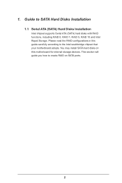
... 1 (Data Mirroring) RAID 1 is called data striping that optimizes two identical hard disk drives to a second drive. 2. Guide to RAID Configurations 2.1 Introduction of RAID This motherboard adopts Intel southbridge chipset that copies and maintains an identical image of the same model and capacity when creating a RAID set. This section will cause...
... 1 (Data Mirroring) RAID 1 is called data striping that optimizes two identical hard disk drives to a second drive. 2. Guide to RAID Configurations 2.1 Introduction of RAID This motherboard adopts Intel southbridge chipset that copies and maintains an identical image of the same model and capacity when creating a RAID set. This section will cause...
RAID Installation Guide
Page 18
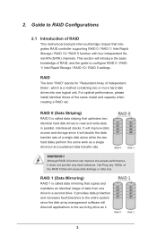
... steps below. STEP 1: Copy Intel® RAID drivers into a USB flash disk You can download the drivers from ASRock's website and unzip the files into a USB flash disk or copy the files from ASRock's motherboard support CD. (Please copy the files under the following directory: 32 bit: ..\i386\Win7_Intel.. 64-bit: ..\AMD64\Win7...
... steps below. STEP 1: Copy Intel® RAID drivers into a USB flash disk You can download the drivers from ASRock's website and unzip the files into a USB flash disk or copy the files from ASRock's motherboard support CD. (Please copy the files under the following directory: 32 bit: ..\i386\Win7_Intel.. 64-bit: ..\AMD64\Win7...
RAID Installation Guide
Page 20
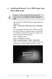
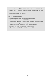
... this problem, you install Windows® 8 64-bit / 7 64-bit on a large hard disk (ex. Reboot your system. (It may take about 5 minutes to install motherboard drivers and utilities. 20 If you will install this problem. After installing Windows® 7 64-bit / 8 64-bit, install the hotfix kb2505454. (This may take...
... this problem, you install Windows® 8 64-bit / 7 64-bit on a large hard disk (ex. Reboot your system. (It may take about 5 minutes to install motherboard drivers and utilities. 20 If you will install this problem. After installing Windows® 7 64-bit / 8 64-bit, install the hotfix kb2505454. (This may take...

Intel Rapid Storage Guide
Page 12
... a RAID volume. 1. When finished press Enter. 12 Switch the SATA Operation Mode option to enable RAID in System BIOS Use the instructions included with your motherboard to RAID. 5. The F6 installation method is not required for Microsoft Windows 7 or Note Microsoft Windows 8. Enable RAID in the system BIOS. 1. Unless you have...
... a RAID volume. 1. When finished press Enter. 12 Switch the SATA Operation Mode option to enable RAID in System BIOS Use the instructions included with your motherboard to RAID. 5. The F6 installation method is not required for Microsoft Windows 7 or Note Microsoft Windows 8. Enable RAID in the system BIOS. 1. Unless you have...

User Manual
Page 2
...including damages for loss of profits, loss of business, loss of data, interruption of business and the like), even if ASRock has been advised of the possibility of their respective companies, and are furnished for identification or explanation and to infringe. ...Products and corporate names appearing in this motherboard contains Perchlorate, a toxic substance controlled in advance. In no responsibility for any interference received, including interference that may not...
...including damages for loss of profits, loss of business, loss of data, interruption of business and the like), even if ASRock has been advised of the possibility of their respective companies, and are furnished for identification or explanation and to infringe. ...Products and corporate names appearing in this motherboard contains Perchlorate, a toxic substance controlled in advance. In no responsibility for any interference received, including interference that may not...
User Manual
Page 4
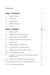
Contents Chapter 1 Introduction 1 1.1 Package Contents 1 1.2 Specifications 2 1.3 Unique Features 7 1.4 Motherboard Layout 11 1.5 I/O Panel 13 Chapter 2 Installation 15 2.1 Installing the CPU 16 2.2 Installing the CPU Fan and Heatsink 19 2.3 Installing Memory Modules (DIMM) 20 2.4 Expansion Slots (...
Contents Chapter 1 Introduction 1 1.1 Package Contents 1 1.2 Specifications 2 1.3 Unique Features 7 1.4 Motherboard Layout 11 1.5 I/O Panel 13 Chapter 2 Installation 15 2.1 Installing the CPU 16 2.2 Installing the CPU Fan and Heatsink 19 2.3 Installing Memory Modules (DIMM) 20 2.4 Expansion Slots (...
User Manual
Page 7
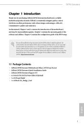
... require technical support related to quality and endurance. Chapter 4 contains the configuration guide of the motherboard and step-by-step installation guides. ASRock website http://www.asrock.com. 1.1 Package Contents • ASRock Z87M Extreme4 Motherboard (Micro ATX Form Factor) • ASRock Z87M Extreme4 Quick Installation Guide • ASRock Z87M Extreme4 Support CD • 4 x Serial ATA (SATA) Data Cables (Optional) • 1 x I/O Panel Shield •...
... require technical support related to quality and endurance. Chapter 4 contains the configuration guide of the motherboard and step-by-step installation guides. ASRock website http://www.asrock.com. 1.1 Package Contents • ASRock Z87M Extreme4 Motherboard (Micro ATX Form Factor) • ASRock Z87M Extreme4 Quick Installation Guide • ASRock Z87M Extreme4 Support CD • 4 x Serial ATA (SATA) Data Cables (Optional) • 1 x I/O Panel Shield •...
User Manual
Page 14
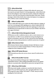
...granted to other users. ASRock XFast RAM ASRock XFast RAM is that it also boosts the speed of Adobe Photoshop 5 times faster. ASRock OMG (Online Management Guard) Administrators are able to modify the system time are required. You may prevent motherboard damages due to dehumidify ...the system after regaining power. If power loss occurs during the BIOS updating process, ASRock Crashless BIOS will power on automatically to dampness by enabling "Dehumidifier Function"....
...granted to other users. ASRock XFast RAM ASRock XFast RAM is that it also boosts the speed of Adobe Photoshop 5 times faster. ASRock OMG (Online Management Guard) Administrators are able to modify the system time are required. You may prevent motherboard damages due to dehumidify ...the system after regaining power. If power loss occurs during the BIOS updating process, ASRock Crashless BIOS will power on automatically to dampness by enabling "Dehumidifier Function"....
User Manual
Page 15
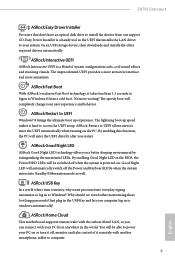
... to UEFI Windows® 8 brings the ultimate boot up speed makes it hard to access the UEFI setup. Z87M Extreme4 ASRock Easy Driver Installer For users that don't have an optical disk drive to install the drivers from our support CD, Easy Driver ...Power and Keyboard LEDs when the system enters into Standby/Hibernation mode as well. ASRock Fast Boot With ASRock's exclusive Fast Boot technology, it takes less than 1.5 seconds to logon to windows automatically! ASRock Home Cloud This motherboard supports remote wake with another smartphone, tablet or computer. 9 English By enabling ...
... to UEFI Windows® 8 brings the ultimate boot up speed makes it hard to access the UEFI setup. Z87M Extreme4 ASRock Easy Driver Installer For users that don't have an optical disk drive to install the drivers from our support CD, Easy Driver ...Power and Keyboard LEDs when the system enters into Standby/Hibernation mode as well. ASRock Fast Boot With ASRock's exclusive Fast Boot technology, it takes less than 1.5 seconds to logon to windows automatically! ASRock Home Cloud This motherboard supports remote wake with another smartphone, tablet or computer. 9 English By enabling ...

User Manual
Page 17
1.4 Motherboard Layout 1 Z87M Extreme4 23 45 USB 2.0 T: USB2 B: USB3 PS2 Keyboard /Mouse ATX12V1 CPU_FAN1 CPU_FAN2 DVI_1 VGA RoHS DDR3_A1 (64 bit, 240-pin module) DDR3_A2 (64 bit, 240-pin ... bit, 240-pin module) ATXPWR1 USB 3.0 HDMI1 T: USB4 B: USB5 6 USB 2.0 eSATA1 T: USB0 B: USB1 24 USB 3.0 T: USB2 B: USB3 Top: RJ-45 LAN 23 PWR_FAN1 CHA_FAN2 CMOS Z87M Extreme4 Top: Battery 7 USB3_0_1 1 Center: REAR SPK Bottom: Optical SPDIF PCI Express 3.0 1 HD_AUDIO1 Central/Bass LINE IN Top: Center: FRONT Bottom: MIC IN 22 PCIE1 SATA3_0_1...
1.4 Motherboard Layout 1 Z87M Extreme4 23 45 USB 2.0 T: USB2 B: USB3 PS2 Keyboard /Mouse ATX12V1 CPU_FAN1 CPU_FAN2 DVI_1 VGA RoHS DDR3_A1 (64 bit, 240-pin module) DDR3_A2 (64 bit, 240-pin ... bit, 240-pin module) ATXPWR1 USB 3.0 HDMI1 T: USB4 B: USB5 6 USB 2.0 eSATA1 T: USB0 B: USB1 24 USB 3.0 T: USB2 B: USB3 Top: RJ-45 LAN 23 PWR_FAN1 CHA_FAN2 CMOS Z87M Extreme4 Top: Battery 7 USB3_0_1 1 Center: REAR SPK Bottom: Optical SPDIF PCI Express 3.0 1 HD_AUDIO1 Central/Bass LINE IN Top: Center: FRONT Bottom: MIC IN 22 PCIE1 SATA3_0_1...

User Manual
Page 21
... place your chassis to ensure that comes with the components. • When placing screws to secure the motherboard to the chassis, please do not touch the ICs. • Whenever you uninstall any motherboard settings. • Make sure to use a grounded wrist strap or touch a safety grounded object before ...you handle the components. • Hold components by the edges and do not overtighten the screws! Before you install motherboard components or change any components, place them on a carpet. Also remember to unplug the power cord before you install the...
... place your chassis to ensure that comes with the components. • When placing screws to secure the motherboard to the chassis, please do not touch the ICs. • Whenever you uninstall any motherboard settings. • Make sure to use a grounded wrist strap or touch a safety grounded object before ...you handle the components. • Hold components by the edges and do not overtighten the screws! Before you install motherboard components or change any components, place them on a carpet. Also remember to unplug the power cord before you install the...

User Manual
Page 24
Please save and replace the cover if the processor is removed. The cover must be placed if you wish to return the motherboard for after service. 18 English
Please save and replace the cover if the processor is removed. The cover must be placed if you wish to return the motherboard for after service. 18 English

User Manual
Page 26
... if you always need to install identical (the same brand, speed, size and chip-type) DDR3 DIMM pairs. 2. otherwise, this motherboard and DIMM may be damaged. English 20 It is unable to install a DDR or DDR2 memory module into the slot at incorrect orientation.... 2.3 Installing Memory Modules (DIMM) This motherboard provides four 240-pin DDR3 (Double Data Rate 3) DIMM slots, and supports Dual Channel Memory Technology. 1. Dual Channel Memory Configuration Priority 1 2 3...
... if you always need to install identical (the same brand, speed, size and chip-type) DDR3 DIMM pairs. 2. otherwise, this motherboard and DIMM may be damaged. English 20 It is unable to install a DDR or DDR2 memory module into the slot at incorrect orientation.... 2.3 Installing Memory Modules (DIMM) This motherboard provides four 240-pin DDR3 (Double Data Rate 3) DIMM slots, and supports Dual Channel Memory Technology. 1. Dual Channel Memory Configuration Priority 1 2 3...

User Manual
Page 28
... or SLITM Mode x8 x8 N/A Three Graphics Cards in 3-Way CrossFireXTM Mode x8 x4 x4 For a better thermal environment, please connect a chassis fan to the motherboard's chassis fan connector (CHA_FAN1 or CHA_FAN2) when using multiple graphics cards. English 22 PCIe slots: PCIE1 (PCIe 3.0 x16 slot) is used for PCI Express x16... necessary hardware settings for the card before you start the installation. 2.4 Expansion Slots (PCI and PCI Express Slots) There are 4 PCI Express slots on the motherboard.
... or SLITM Mode x8 x8 N/A Three Graphics Cards in 3-Way CrossFireXTM Mode x8 x4 x4 For a better thermal environment, please connect a chassis fan to the motherboard's chassis fan connector (CHA_FAN1 or CHA_FAN2) when using multiple graphics cards. English 22 PCIe slots: PCIE1 (PCIe 3.0 x16 slot) is used for PCI Express x16... necessary hardware settings for the card before you start the installation. 2.4 Expansion Slots (PCI and PCI Express Slots) There are 4 PCI Express slots on the motherboard.

User Manual
Page 30
... reading or writing data. You may differ by chassis. Press the reset switch to restart the computer if the computer freezes and fails to the motherboard. The front panel design may configure the way to the pin assignments below. A front panel module mainly consists of power switch, reset switch, power LED...
... reading or writing data. You may differ by chassis. Press the reset switch to restart the computer if the computer freezes and fails to the motherboard. The front panel design may configure the way to the pin assignments below. A front panel module mainly consists of power switch, reset switch, power LED...

User Manual
Page 31
...11, No. 18) USB_PWR PP+ GND DUMMY 1 GND P+ PUSB_PWR Besides two USB 2.0 ports on the I/O panel, there are one header on this motherboard. If the eSATA port on the rear I /O panel, there are three headers on this header to 6.0 Gb/s data transfer rate. Each USB 2.0... data cables for internal storage devices with up to indicate the system's power status. PLED+ PLED+ Please connect the chassis power LED to this motherboard. English 25 Z87M Extreme4 SATA3_4_5 SATA3_2_3 SATA3_0_1 Power LED Header (3-pin PLED1) (see p.11, No. 18) Serial ATA3 Connectors (SATA3_0_1: see p.11, No. 8)...
...11, No. 18) USB_PWR PP+ GND DUMMY 1 GND P+ PUSB_PWR Besides two USB 2.0 ports on the I/O panel, there are one header on this motherboard. If the eSATA port on the rear I /O panel, there are three headers on this header to 6.0 Gb/s data transfer rate. Each USB 2.0... data cables for internal storage devices with up to indicate the system's power status. PLED+ PLED+ Please connect the chassis power LED to this motherboard. English 25 Z87M Extreme4 SATA3_4_5 SATA3_2_3 SATA3_0_1 Power LED Header (3-pin PLED1) (see p.11, No. 18) Serial ATA3 Connectors (SATA3_0_1: see p.11, No. 8)...

User Manual
Page 33
..., please plug it to Pin 1-3. If you plan to connect a 3-Pin CPU fan, please connect it along Pin 1 and Pin 13. This motherboard provides an 8-pin ATX 12V power connector. Z87M Extreme4 CPU Fan Connectors (4-pin CPU_FAN1) (see p.11, No. 2) (3-pin CPU_FAN2) (see p.11, No. 14) IRTX +5VSB DUMMY 1 GND IRRX This header...
..., please plug it to Pin 1-3. If you plan to connect a 3-Pin CPU fan, please connect it along Pin 1 and Pin 13. This motherboard provides an 8-pin ATX 12V power connector. Z87M Extreme4 CPU Fan Connectors (4-pin CPU_FAN1) (see p.11, No. 2) (3-pin CPU_FAN2) (see p.11, No. 14) IRTX +5VSB DUMMY 1 GND IRRX This header...

User Manual
Page 34
... helps enhance network security, protects digital identities, and ensures platform integrity. English 28 TPM Header (17-pin TPMS1) (see p.11, No. 20) 1 GND Signal This motherboard supports CASE OPEN detection feature that detects if the chassis cove has been removed. This feature requires a chassis with chassis intrusion detection design. Chassis Intrusion...
... helps enhance network security, protects digital identities, and ensures platform integrity. English 28 TPM Header (17-pin TPMS1) (see p.11, No. 20) 1 GND Signal This motherboard supports CASE OPEN detection feature that detects if the chassis cove has been removed. This feature requires a chassis with chassis intrusion detection design. Chassis Intrusion...


