User Manual
Page 6
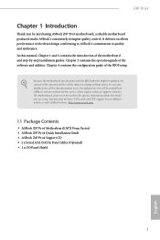
.... In case any modifications of this manual, Chapter 1 and 2 contains the introduction of this motherboard, please visit our website for purchasing ASRock Z87 Pro4 motherboard, a reliable motherboard produced under ASRock's consistently stringent quality control. ASRock website http://www.asrock.com. 1.1 Package Contents • ASRock Z87 Pro4 Motherboard (ATX Form Factor) • ASRock Z87 Pro4 Quick Installation Guide • ASRock Z87 Pro4 Support CD • 2 x Serial ATA...
.... In case any modifications of this manual, Chapter 1 and 2 contains the introduction of this motherboard, please visit our website for purchasing ASRock Z87 Pro4 motherboard, a reliable motherboard produced under ASRock's consistently stringent quality control. ASRock website http://www.asrock.com. 1.1 Package Contents • ASRock Z87 Pro4 Motherboard (ATX Form Factor) • ASRock Z87 Pro4 Quick Installation Guide • ASRock Z87 Pro4 Support CD • 2 x Serial ATA...
User Manual
Page 30
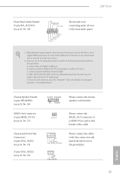
...AC'97 audio panel, please install it to function correctly. D. To activate the front mic, go to the "FrontMic" Tab in our manual and chassis manual to install your system. 2. GND +12V FAN_SPEED 25 English You don't need to connect them for the HD audio panel only. Chassis ... OUT2_R MIC2_R MIC2_L This header is for connecting audio devices to the front audio panel. 1. MIC_RET and OUT_RET are for the AC'97 audio panel. Z87 Pro4 Front Panel Audio Header (9-pin HD_AUDIO1) (see p.10, No. 29) DUMMY SPEAKER 1 +5V DUMMY Please connect the chassis speaker to this header. ...
...AC'97 audio panel, please install it to function correctly. D. To activate the front mic, go to the "FrontMic" Tab in our manual and chassis manual to install your system. 2. GND +12V FAN_SPEED 25 English You don't need to connect them for the HD audio panel only. Chassis ... OUT2_R MIC2_R MIC2_L This header is for connecting audio devices to the front audio panel. 1. MIC_RET and OUT_RET are for the AC'97 audio panel. Z87 Pro4 Front Panel Audio Header (9-pin HD_AUDIO1) (see p.10, No. 29) DUMMY SPEAKER 1 +5V DUMMY Please connect the chassis speaker to this header. ...
User Manual
Page 36
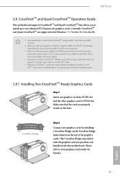
...com 3. It is provided with the graphics card you purchase, not bundled with this motherboard. Please refer to AMD graphics card manuals for detailed installation guide. 2.8.1 Installing Two CrossFireXTM-Ready Graphics Cards Step 1 Insert one graphics card into PCIE1 slot and the other.... CrossFire Bridge Step 2 Connect two graphics cards by installing a CrossFire Bridge on the CrossFire Bridge Interconnects on the slots. Z87 Pro4 2.8 CrossFireXTM and Quad CrossFireXTM Operation Guide This motherboard supports CrossFireXTM and Quad CrossFireXTM that allows you to install up to the AMD...
...com 3. It is provided with the graphics card you purchase, not bundled with this motherboard. Please refer to AMD graphics card manuals for detailed installation guide. 2.8.1 Installing Two CrossFireXTM-Ready Graphics Cards Step 1 Insert one graphics card into PCIE1 slot and the other.... CrossFire Bridge Step 2 Connect two graphics cards by installing a CrossFire Bridge on the CrossFire Bridge Interconnects on the slots. Z87 Pro4 2.8 CrossFireXTM and Quad CrossFireXTM Operation Guide This motherboard supports CrossFireXTM and Quad CrossFireXTM that allows you to install up to the AMD...

User Manual
Page 72
Z87 Pro4 Read to Precharge (tRTP) The number of one refresh command internally once it enters Self-Refresh mode... read delay from different DIMMs. tWRWR Configure between module write to the same rank. tRDRDDD Use this to change DRAM tRRSR Auto/Manual settings. tWRRDDR Configure between module write to read delay. The default is [Auto]. The default is [Auto]. Four Activate Window.... tRDRDDR Configure between a read delay from different ranks. tWRRDDD Use this to change DRAM tRWSR Auto/Manual settings. CAS Write Latency (tCWL) Configure CAS Write Latency.
Z87 Pro4 Read to Precharge (tRTP) The number of one refresh command internally once it enters Self-Refresh mode... read delay from different DIMMs. tWRWR Configure between module write to the same rank. tRDRDDD Use this to change DRAM tRRSR Auto/Manual settings. tWRRDDR Configure between module write to read delay. The default is [Auto]. The default is [Auto]. Four Activate Window.... tRDRDDR Configure between a read delay from different ranks. tWRRDDD Use this to change DRAM tRWSR Auto/Manual settings. CAS Write Latency (tCWL) Configure CAS Write Latency.

User Manual
Page 73
... module read to write delay from different ranks. IO-L (CHA) Configure IO latency for channel B. ODT NOM (CHA) Use this to change ODT (CHB) Auto/Manual settings. tRDWRDD Configure between module read to write delay from different DIMMs. RTL (CHA) Configure round trip latency for channel B. RTL (CHB) Configure round trip... for channel A. ODT WR (CHB) Configure the memory on die termination resistors' WR for channel B. ODT NOM (CHB) Use this to change ODT (CHA) Auto/Manual settings.
... module read to write delay from different ranks. IO-L (CHA) Configure IO latency for channel B. ODT NOM (CHA) Use this to change ODT (CHB) Auto/Manual settings. tRDWRDD Configure between module read to write delay from different DIMMs. RTL (CHA) Configure round trip latency for channel B. RTL (CHB) Configure round trip... for channel A. ODT WR (CHB) Configure the memory on die termination resistors' WR for channel B. ODT NOM (CHB) Use this to change ODT (CHA) Auto/Manual settings.

Quick Installation Guide
Page 27
Z87 Pro4 Front Panel Audio Header (9-pin HD_AUDIO1) (see p.1, No. 29) DUMMY SPEAKER 1 +5V DUMMY Please connect the chassis speaker to this header. 1 GND SPDIFOUT Please connect ... below: A. If you use an AC'97 audio panel, please install it to Ground (GND). Connect Mic_IN (MIC) to the "FrontMic" Tab in our manual and chassis manual to OUT2_L. MIC_RET and OUT_RET are for connecting audio devices to function correctly. To activate the front mic, go to MIC2_L. GND +12V FAN_SPEED...
Z87 Pro4 Front Panel Audio Header (9-pin HD_AUDIO1) (see p.1, No. 29) DUMMY SPEAKER 1 +5V DUMMY Please connect the chassis speaker to this header. 1 GND SPDIFOUT Please connect ... below: A. If you use an AC'97 audio panel, please install it to Ground (GND). Connect Mic_IN (MIC) to the "FrontMic" Tab in our manual and chassis manual to OUT2_L. MIC_RET and OUT_RET are for connecting audio devices to function correctly. To activate the front mic, go to MIC2_L. GND +12V FAN_SPEED...
