
Intel Smart Response Installation Guide
Page 1
...Start Menu or by step instructions below. For the new version RST driver, please check our website for the latest information: http://www.asrock.com * Before you use RST function, you want to a RAID mode system, then install all performance testing, chose "Maximized" mode....! 3. Complete initial system setup, including installing the OS to use Enhanced or Maximized Mode. 6. Intel Smart Response Technology Installation Guide This motherboard supports Intel Smart Response Technology. It is not necessary to desktop, open , click on the "Enable Acceleration" button on the GUI panel...
...Start Menu or by step instructions below. For the new version RST driver, please check our website for the latest information: http://www.asrock.com * Before you use RST function, you want to a RAID mode system, then install all performance testing, chose "Maximized" mode....! 3. Complete initial system setup, including installing the OS to use Enhanced or Maximized Mode. 6. Intel Smart Response Technology Installation Guide This motherboard supports Intel Smart Response Technology. It is not necessary to desktop, open , click on the "Enable Acceleration" button on the GUI panel...
RAID Installation Guide
Page 2
Please read the RAID configurations in this motherboard for internal storage devices. Guide to create RAID on this guide carefully according to the Intel southbridge chipset that your motherboard adopts. You may install SATA hard disks on SATA ports. 2 1. This section will guide you how to SATA Hard Disks Installation 1.1 Serial ATA (SATA) Hard Disks Installation Intel chipset supports Serial ATA (SATA) hard disks with RAID functions, including RAID 0, RAID 1, RAID 5, RAID 10 and Intel Rapid Storage.
Please read the RAID configurations in this motherboard for internal storage devices. Guide to create RAID on this guide carefully according to the Intel southbridge chipset that your motherboard adopts. You may install SATA hard disks on SATA ports. 2 1. This section will guide you how to SATA Hard Disks Installation 1.1 Serial ATA (SATA) Hard Disks Installation Intel chipset supports Serial ATA (SATA) hard disks with RAID functions, including RAID 0, RAID 1, RAID 5, RAID 10 and Intel Rapid Storage.
RAID Installation Guide
Page 3
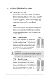
... data from one logical unit. Although RAID 0 function can improve the access performance, it will direct all applications to RAID Configurations 2.1 Introduction of RAID This motherboard adopts Intel southbridge chipset that copies and maintains an identical image of Independent Disks", which is called data striping that optimizes two identical hard disk...
... data from one logical unit. Although RAID 0 function can improve the access performance, it will direct all applications to RAID Configurations 2.1 Introduction of RAID This motherboard adopts Intel southbridge chipset that copies and maintains an identical image of Independent Disks", which is called data striping that optimizes two identical hard disk...
RAID Installation Guide
Page 18
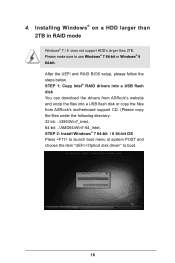
... steps below. 4. STEP 1: Copy Intel® RAID drivers into a USB flash disk You can download the drivers from ASRock's website and unzip the files into a USB flash disk or copy the files from ASRock's motherboard support CD. (Please copy the files under the following directory: 32 bit: ..\i386\Win7_Intel.. 64-bit: ..\AMD64\Win7...
... steps below. 4. STEP 1: Copy Intel® RAID drivers into a USB flash disk You can download the drivers from ASRock's website and unzip the files into a USB flash disk or copy the files from ASRock's motherboard support CD. (Please copy the files under the following directory: 32 bit: ..\i386\Win7_Intel.. 64-bit: ..\AMD64\Win7...
RAID Installation Guide
Page 20
... instructions below to reboot.) D. Please start to boot into Windows® or install driver/utilities. E. Reboot your system. (It may take more time to install motherboard drivers and utilities. 20
... instructions below to reboot.) D. Please start to boot into Windows® or install driver/utilities. E. Reboot your system. (It may take more time to install motherboard drivers and utilities. 20

Intel Rapid Storage Guide
Page 12
Enable RAID in System BIOS Use the instructions included with your motherboard to select the physical disks. 6. When the Intel Rapid Storage Technology option ROM status screen appears during operating system setup. When finished press Enter. 12 ...
Enable RAID in System BIOS Use the instructions included with your motherboard to select the physical disks. 6. When the Intel Rapid Storage Technology option ROM status screen appears during operating system setup. When finished press Enter. 12 ...

User Manual
Page 2
...to change without written consent of this documentation may or may cause undesired operation. Version 1.0 Published May 2013 Copyright©2013 ASRock INC. In no responsibility for any errors or omissions that may not be constructed as a commitment by the California Legislature. ... please follow the related regulations in the documentation or product. Copyright Notice: No part of this motherboard contains Perchlorate, a toxic substance controlled in this documentation, ASRock does not provide warranty of the FCC Rules. This device complies with Part 15 of any defect...
...to change without written consent of this documentation may or may cause undesired operation. Version 1.0 Published May 2013 Copyright©2013 ASRock INC. In no responsibility for any errors or omissions that may not be constructed as a commitment by the California Legislature. ... please follow the related regulations in the documentation or product. Copyright Notice: No part of this motherboard contains Perchlorate, a toxic substance controlled in this documentation, ASRock does not provide warranty of the FCC Rules. This device complies with Part 15 of any defect...
User Manual
Page 4
Contents Chapter 1 Introduction 1 1.1 Package Contents 1 1.2 Specifications 2 1.3 Unique Features 7 1.4 Motherboard Layout 11 1.5 I/O Panel 13 1.6 WiFi + BT Module and ASRock Wi-SD Box 15 Chapter 2 Installation 19 2.1 Installing the CPU 20 2.2 Installing the CPU Fan and Heatsink 23 2.3 Installing Memory Modules (DIMM) 24 2.4 Expansion Slots (...
Contents Chapter 1 Introduction 1 1.1 Package Contents 1 1.2 Specifications 2 1.3 Unique Features 7 1.4 Motherboard Layout 11 1.5 I/O Panel 13 1.6 WiFi + BT Module and ASRock Wi-SD Box 15 Chapter 2 Installation 19 2.1 Installing the CPU 20 2.2 Installing the CPU Fan and Heatsink 23 2.3 Installing Memory Modules (DIMM) 24 2.4 Expansion Slots (...

User Manual
Page 7
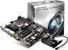
...://www.asrock.com. 1.1 Package Contents • ASRock Z87 Extreme9/ac Motherboard (ATX Form Factor) • ASRock Z87 Extreme9/ac Quick Installation Guide • ASRock Z87 Extreme9/ac Support CD • 10 x Serial ATA (SATA) Data Cables (Optional) • 1 x I/O Panel Shield • 2 x ASRock SLI_Bridge Cards • 1 x ASRock SLI_Bridge_3S Card • 1 x ASRock 3-Way SLI Bridge Card • 1 x ASRock Wi-SD Box • 12 Screws (for purchasing ASRock Z87 Extreme9/ac motherboard, a reliable motherboard produced under ASRock's consistently...
...://www.asrock.com. 1.1 Package Contents • ASRock Z87 Extreme9/ac Motherboard (ATX Form Factor) • ASRock Z87 Extreme9/ac Quick Installation Guide • ASRock Z87 Extreme9/ac Support CD • 10 x Serial ATA (SATA) Data Cables (Optional) • 1 x I/O Panel Shield • 2 x ASRock SLI_Bridge Cards • 1 x ASRock SLI_Bridge_3S Card • 1 x ASRock 3-Way SLI Bridge Card • 1 x ASRock Wi-SD Box • 12 Screws (for purchasing ASRock Z87 Extreme9/ac motherboard, a reliable motherboard produced under ASRock's consistently...
User Manual
Page 14
...And it reduces the frequency of accessing your current PC and the devices connected. You may prevent motherboard damages due to dehumidify the system after regaining power. ASRock Internet Flash ASRock Internet Flash downloads and updates the latest UEFI firmware version from our servers for you to copy...note that BIOS files need to be used under Windows® 32-bit operating systems. ASRock XFast RAM shortens the loading time of Adobe Photoshop 5 times faster. ASRock Easy RAID Installer ASRock Easy RAID Installer can start installing the OS in the root directory of your USB ...
...And it reduces the frequency of accessing your current PC and the devices connected. You may prevent motherboard damages due to dehumidify the system after regaining power. ASRock Internet Flash ASRock Internet Flash downloads and updates the latest UEFI firmware version from our servers for you to copy...note that BIOS files need to be used under Windows® 32-bit operating systems. ASRock XFast RAM shortens the loading time of Adobe Photoshop 5 times faster. ASRock Easy RAID Installer ASRock Easy RAID Installer can start installing the OS in the root directory of your USB ...

User Manual
Page 15
...plug in the USB Key and let your system via an USB storage device, then downloads and installs the other required drivers automatically. Z87 Extreme9/ac ASRock Easy Driver Installer For users that don't have an optical disk drive to install the drivers from our support CD, Easy Driver Installer ... the ultimate boot up speed makes it hard to enter the UEFI automatically when turning on the PC. ASRock Restart to your computer log in to Windows? ASRock Home Cloud This motherboard supports remote wake with the onboard Intel LAN, so you can connect with another smartphone, tablet or computer...
...plug in the USB Key and let your system via an USB storage device, then downloads and installs the other required drivers automatically. Z87 Extreme9/ac ASRock Easy Driver Installer For users that don't have an optical disk drive to install the drivers from our support CD, Easy Driver Installer ... the ultimate boot up speed makes it hard to enter the UEFI automatically when turning on the PC. ASRock Restart to your computer log in to Windows? ASRock Home Cloud This motherboard supports remote wake with the onboard Intel LAN, so you can connect with another smartphone, tablet or computer...

User Manual
Page 17
Z87 Extreme9/ac 1.4 Motherboard Layout USB 2.0 T: USB0 B: USB1 PS2 Keyboard /Mouse 1 RJ-45 RJ-45 LAN2 LAN1 CHA_FAN3 LAN LAN 2 3 4 56 78 ATX12V1 ATX12V2 CPU_FAN1 CPU_FAN2 PWR_FAN1 DP_1 HDMI1 ... 1 USB3_8_9 1 Top: Center: FRONT Bottom: MIC IN 11 CHA_FAN2 33 PCIE1 SATA3_A3_A4 SATA3_A1_A2 RoHS PCIE2 12 Purity SoundTM 13 PCIE3 14 SATA3_0_1 SATA3_2_3 Z87 Extreme9/ac Super Intel 15 I/O PCIE4 Z87 16 SATA3_4_5 WiFi-802.11ac Module MINI_PCIE1 PCIE5 HD_AUDIO1 1 1 COM1 PCIE6 SLI/XFIRE_PWR1 IR1 1 CMOS Battery Dr. Debug USB2_3 USB4_5 1 1 USB6_7 1 USB8 ...
Z87 Extreme9/ac 1.4 Motherboard Layout USB 2.0 T: USB0 B: USB1 PS2 Keyboard /Mouse 1 RJ-45 RJ-45 LAN2 LAN1 CHA_FAN3 LAN LAN 2 3 4 56 78 ATX12V1 ATX12V2 CPU_FAN1 CPU_FAN2 PWR_FAN1 DP_1 HDMI1 ... 1 USB3_8_9 1 Top: Center: FRONT Bottom: MIC IN 11 CHA_FAN2 33 PCIE1 SATA3_A3_A4 SATA3_A1_A2 RoHS PCIE2 12 Purity SoundTM 13 PCIE3 14 SATA3_0_1 SATA3_2_3 Z87 Extreme9/ac Super Intel 15 I/O PCIE4 Z87 16 SATA3_4_5 WiFi-802.11ac Module MINI_PCIE1 PCIE5 HD_AUDIO1 1 1 COM1 PCIE6 SLI/XFIRE_PWR1 IR1 1 CMOS Battery Dr. Debug USB2_3 USB4_5 1 1 USB6_7 1 USB8 ...
User Manual
Page 21
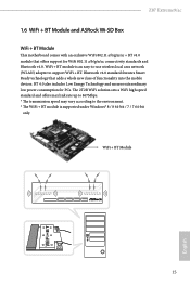
Z87 Extreme9/ac 1.6 WiFi + BT Module and ASRock Wi-SD Box WiFi + BT Module This motherboard comes with an exclusive WiFi 802.11 a/b/g/n/ac + BT v4.0 module that adds a whole new class of functionality into the mobile devices. The 2T2R WiFi solution sets a WiFi high speed standard and ... under Windows® 8 / 8 64-bit / 7 / 7 64-bit only. BT 4.0 also includes Low Energy Technology and ensures extraordinary low power consumption for WiFi 802.11 a/b/g/n/ac connectivity standards and Bluetooth v4.0. Bluetooth v4.0 standard features Smart Ready technology that offers support for PCs.
Z87 Extreme9/ac 1.6 WiFi + BT Module and ASRock Wi-SD Box WiFi + BT Module This motherboard comes with an exclusive WiFi 802.11 a/b/g/n/ac + BT v4.0 module that adds a whole new class of functionality into the mobile devices. The 2T2R WiFi solution sets a WiFi high speed standard and ... under Windows® 8 / 8 64-bit / 7 / 7 64-bit only. BT 4.0 also includes Low Energy Technology and ensures extraordinary low power consumption for WiFi 802.11 a/b/g/n/ac connectivity standards and Bluetooth v4.0. Bluetooth v4.0 standard features Smart Ready technology that offers support for PCs.

User Manual
Page 24
USB 3.0 USB 3.0 Step 5 Screw ASRock Wi-SD Box to the Wi-SD Box. Step 7 Connect the floppy drive 4 pin power Wi-SD connector to the drive bay with screws. Step 6 Attach the cords to the WiFi + BT module on the motherboard. Step 8 Plug the Front USB 3.0 cable into the USB 3.0 header on your motherboard. English 18
USB 3.0 USB 3.0 Step 5 Screw ASRock Wi-SD Box to the Wi-SD Box. Step 7 Connect the floppy drive 4 pin power Wi-SD connector to the drive bay with screws. Step 6 Attach the cords to the WiFi + BT module on the motherboard. Step 8 Plug the Front USB 3.0 cable into the USB 3.0 header on your motherboard. English 18

User Manual
Page 25
... Precautions Take note of the following precautions before you install the motherboard, study the configuration of your motherboard directly on a grounded anti-static pad or in the bag that the motherboard fits into it. Z87 Extreme9/ac Chapter 2 Installation This is an ATX form factor motherboard. Also remember to use a grounded wrist strap or touch a safety grounded...
... Precautions Take note of the following precautions before you install the motherboard, study the configuration of your motherboard directly on a grounded anti-static pad or in the bag that the motherboard fits into it. Z87 Extreme9/ac Chapter 2 Installation This is an ATX form factor motherboard. Also remember to use a grounded wrist strap or touch a safety grounded...

User Manual
Page 28
Please save and replace the cover if the processor is removed. The cover must be placed if you wish to return the motherboard for after service. 22 English
Please save and replace the cover if the processor is removed. The cover must be placed if you wish to return the motherboard for after service. 22 English

User Manual
Page 30
... the DIMM if you always need to install a DDR or DDR2 memory module into the slot at incorrect orientation. otherwise, this motherboard and DIMM may be damaged. English 24 Dual Channel Memory Configuration Priority 1 2 3 DDR3_A1 Populated Populated DDR3_A2 Populated Populated DDR3_B1 Populated Populated DDR3_B2 Populated Populated The ...
... the DIMM if you always need to install a DDR or DDR2 memory module into the slot at incorrect orientation. otherwise, this motherboard and DIMM may be damaged. English 24 Dual Channel Memory Configuration Priority 1 2 3 DDR3_A1 Populated Populated DDR3_A2 Populated Populated DDR3_B1 Populated Populated DDR3_B2 Populated Populated The ...

User Manual
Page 32
... Graphics Cards in 4-Way CrossFireXTM Mode x8 N/A x8 x8 x8 or 4-Way SLITM Mode English For a better thermal environment, please connect a chassis fan to the motherboard's chassis fan connector (CHA_FAN1, CHA_FAN2 or CHA_FAN3) when using multiple graphics cards. 26 Please read the documentation of the expansion card and make sure that...) is used for WiFi + BT module. 2.4 Expansion Slots (PCI and PCI Express Slots) There are 6 PCI Express slots and 1 mini-PCI Express slot on the motherboard.
... Graphics Cards in 4-Way CrossFireXTM Mode x8 N/A x8 x8 x8 or 4-Way SLITM Mode English For a better thermal environment, please connect a chassis fan to the motherboard's chassis fan connector (CHA_FAN1, CHA_FAN2 or CHA_FAN3) when using multiple graphics cards. 26 Please read the documentation of the expansion card and make sure that...) is used for WiFi + BT module. 2.4 Expansion Slots (PCI and PCI Express Slots) There are 6 PCI Express slots and 1 mini-PCI Express slot on the motherboard.

User Manual
Page 34
... the positive and negative pins before connecting the cables. Press the reset switch to restart the computer if the computer freezes and fails to the motherboard. The front panel design may configure the way to turn off (S5). Placing jumper caps over these headers and connectors. You may differ by chassis...
... the positive and negative pins before connecting the cables. Press the reset switch to restart the computer if the computer freezes and fails to the motherboard. The front panel design may configure the way to turn off (S5). Placing jumper caps over these headers and connectors. You may differ by chassis...

User Manual
Page 35
...p.11, No. 16) (SATA3_A1_A2: see p.11, No. 12) (SATA3_A3_A4: see p.11, No. 13) Please connect the chassis power LED to this motherboard. If the eSATA port on the rear I /O panel, there are three headers and one port on the I /O has been connected, the internal SATA3_A4 ...up to indicate the system's power status. These ten SATA3 connectors support SATA data cables for your bootable devices. SATA3_4_5 SATA3_2_3 SATA3_0_1 SATA3_A3_A4 SATA3_A1_A2 English Z87 Extreme9/ac Power LED Header (3-pin PLED1) (see p.11, No. 25) USB_PWR PP+ GND DUMMY 1 GND P+ PUSB_PWR Besides two USB 2.0 ports...
...p.11, No. 16) (SATA3_A1_A2: see p.11, No. 12) (SATA3_A3_A4: see p.11, No. 13) Please connect the chassis power LED to this motherboard. If the eSATA port on the rear I /O panel, there are three headers and one port on the I /O has been connected, the internal SATA3_A4 ...up to indicate the system's power status. These ten SATA3 connectors support SATA data cables for your bootable devices. SATA3_4_5 SATA3_2_3 SATA3_0_1 SATA3_A3_A4 SATA3_A1_A2 English Z87 Extreme9/ac Power LED Header (3-pin PLED1) (see p.11, No. 25) USB_PWR PP+ GND DUMMY 1 GND P+ PUSB_PWR Besides two USB 2.0 ports...

