
User Manual
Page 2
... accept any interference received, including interference that may appear in this manual. CALIFORNIA, USA ONLY The Lithium battery adopted on this motherboard contains Perchlorate, a toxic substance controlled in Perchlorate Best Management Practices (BMP) regulations passed by the purchaser for identification or explanation... and to the owners' benefit, without intent to change without written consent of ASRock Inc. Products and corporate names appearing in this manual may or may not be registered trademarks or copyrights of their ...
... accept any interference received, including interference that may appear in this manual. CALIFORNIA, USA ONLY The Lithium battery adopted on this motherboard contains Perchlorate, a toxic substance controlled in Perchlorate Best Management Practices (BMP) regulations passed by the purchaser for identification or explanation... and to the owners' benefit, without intent to change without written consent of ASRock Inc. Products and corporate names appearing in this manual may or may not be registered trademarks or copyrights of their ...
User Manual
Page 3
Contents 1. Introduction 5 1.1 Package Contents 5 1.2 Specifications 6 1.3 Unique Features 10 1.4 Motherboard Layout (Z77M-ITX 13 1.5 Motherboard Layout (H77M-ITX 15 1.6 Motherboard Layout (B75M-ITX 17 1.7 Motherboard Layout (H61M-ITX 19 1.8 I/O Panel (Z77M-ITX 21 1.9 I/O Panel (H77M-ITX 22 1.10 I/O Panel (B75M-ITX 23 1.11 I/O Panel (H61M-ITX 24 2. Installation 25 2.1 Installing the CPU 26 2.2 Installing the CPU Fan and Heatsink 28 2.3 Installing Memory Modules (DIMM...
Contents 1. Introduction 5 1.1 Package Contents 5 1.2 Specifications 6 1.3 Unique Features 10 1.4 Motherboard Layout (Z77M-ITX 13 1.5 Motherboard Layout (H77M-ITX 15 1.6 Motherboard Layout (B75M-ITX 17 1.7 Motherboard Layout (H61M-ITX 19 1.8 I/O Panel (Z77M-ITX 21 1.9 I/O Panel (H77M-ITX 22 1.10 I/O Panel (B75M-ITX 23 1.11 I/O Panel (H61M-ITX 24 2. Installation 25 2.1 Installing the CPU 26 2.2 Installing the CPU Fan and Heatsink 28 2.3 Installing Memory Modules (DIMM...

User Manual
Page 5
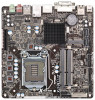
... find the latest VGA cards and CPU support list on ASRock's website. www.asrock.com/support/index.asp 1.1 Package Contents ASRock Z77TM-ITX / H77TM-ITX / B75TM-ITX / H61TM-ITX Motherboard (Thin Mini-ITX Form Factor: 6.7-in x 6.7-in, 17.0 cm x 17.0 cm) ASRock Z77TM-ITX / H77TM-ITX / B75TM-ITX / H61TM-ITX Quick Installation Guide ASRock Z77TM-ITX / H77TM-ITX / B75TM-ITX / H61TM-ITX Support CD 1 x I/O Panel Shield 5 Introduction Thank you are using. It...
... find the latest VGA cards and CPU support list on ASRock's website. www.asrock.com/support/index.asp 1.1 Package Contents ASRock Z77TM-ITX / H77TM-ITX / B75TM-ITX / H61TM-ITX Motherboard (Thin Mini-ITX Form Factor: 6.7-in x 6.7-in, 17.0 cm x 17.0 cm) ASRock Z77TM-ITX / H77TM-ITX / B75TM-ITX / H61TM-ITX Quick Installation Guide ASRock Z77TM-ITX / H77TM-ITX / B75TM-ITX / H61TM-ITX Support CD 1 x I/O Panel Shield 5 Introduction Thank you are using. It...

User Manual
Page 25
Chapter 2: Installation This is a Thin Mini-ITX form factor motherboard. Whenever you uninstall any motherboard settings. 1. Failure to do so may damage the motherboard. 25 In order to avoid damage from static electricity to motherboard components. 2. Make sure to the chassis, please do not ... components, place them on a carpet. Before you install the motherboard, study the configuration of the following precautions before installing or removing the motherboard. When placing screws to secure the motherboard to unplug the power cord before you handle the components. 3....
Chapter 2: Installation This is a Thin Mini-ITX form factor motherboard. Whenever you uninstall any motherboard settings. 1. Failure to do so may damage the motherboard. 25 In order to avoid damage from static electricity to motherboard components. 2. Make sure to the chassis, please do not ... components, place them on a carpet. Before you install the motherboard, study the configuration of the following precautions before installing or removing the motherboard. When placing screws to secure the motherboard to unplug the power cord before you handle the components. 3....

User Manual
Page 27
... the load plate onto the IHS. Please save and replace the cover if the processor is within the socket and properly mated to return the motherboard for after service. 27 Step 2-3.Carefully place the CPU into the socket. orientation key notch Pin1 alignment key orientation key notch 1155-Pin CPU alignment...
... the load plate onto the IHS. Please save and replace the cover if the processor is within the socket and properly mated to return the motherboard for after service. 27 Step 2-3.Carefully place the CPU into the socket. orientation key notch Pin1 alignment key orientation key notch 1155-Pin CPU alignment...

User Manual
Page 28
... cable does not interfere with the fan's operation or contact other . Connect the CPU fan connector with the fan header on the motherboard. Secure redundant cable with tie-wrap to MB header p.13/15/17/19, No. 22). Repeat with Intel 1155-Pin CPU ...heatsink to illustrate the installation of heatsink and cooling fan compliant with the remaining fasteners. 2.2 Installing the CPU Fan and Heatsink This motherboard is an example to improve heat dissipation. Rotate the fastener clockwise, then press the fastener caps down the fasteners without rotating them clockwise...
... cable does not interfere with the fan's operation or contact other . Connect the CPU fan connector with the fan header on the motherboard. Secure redundant cable with tie-wrap to MB header p.13/15/17/19, No. 22). Repeat with Intel 1155-Pin CPU ...heatsink to illustrate the installation of heatsink and cooling fan compliant with the remaining fasteners. 2.2 Installing the CPU Fan and Heatsink This motherboard is an example to improve heat dissipation. Rotate the fastener clockwise, then press the fastener caps down the fasteners without rotating them clockwise...
User Manual
Page 29
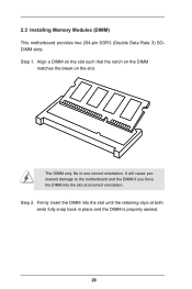
Step 1. 2.3 Installing Memory Modules (DIMM) This motherboard provides two 204-pin DDR3 (Double Data Rate 3) SODIMM slots. Align a DIMM on the slot such that the notch on the DIMM matches the break on the slot. Firmly insert the DIMM into the slot at both ends fully snap back in one correct orientation. It will cause permanent damage to the motherboard and the DIMM if you force the DIMM into the slot until the retaining clips at incorrect orientation. Step 2. The DIMM only fits in place and the DIMM is properly seated. 29
Step 1. 2.3 Installing Memory Modules (DIMM) This motherboard provides two 204-pin DDR3 (Double Data Rate 3) SODIMM slots. Align a DIMM on the slot such that the notch on the DIMM matches the break on the slot. Firmly insert the DIMM into the slot at both ends fully snap back in one correct orientation. It will cause permanent damage to the motherboard and the DIMM if you force the DIMM into the slot until the retaining clips at incorrect orientation. Step 2. The DIMM only fits in place and the DIMM is properly seated. 29
User Manual
Page 30
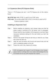
... screws. Mini-PCIE Slot: MINI_PCIE1 is used for later use . PCIE slots: The x4 lane width PCIE1 (PCIE 3.0 x4 slot) is completely seated on this motherboard. Keep the screws for PCI Express expansion cards. Fasten the card to use . PCIE1 slot supports Gen 3 speed.
... screws. Mini-PCIE Slot: MINI_PCIE1 is used for later use . PCIE slots: The x4 lane width PCIE1 (PCIE 3.0 x4 slot) is completely seated on this motherboard. Keep the screws for PCI Express expansion cards. Fasten the card to use . PCIE1 slot supports Gen 3 speed.

User Manual
Page 31
STEP 3: Connect the other end of the SATA data cable to the hard disk. SATA2 / SATA3 Connectors (SATA_0: see p.13/15/17/19, No. 6) SATA_1 (SATA_1: see p.13/15/17/19, No. 2) SATA_0 These two SATA2 / SATA3 connectors support SATA data cables for internal storage devices. 31 2.5 Installing Serial SATA2 / SATA3 Hard Disks STEP 1: Connect the SATA power cable to the motherboard's SATA2 connectors. STEP 2: Connect one end of the SATA data cable to the hard disk.
STEP 3: Connect the other end of the SATA data cable to the hard disk. SATA2 / SATA3 Connectors (SATA_0: see p.13/15/17/19, No. 6) SATA_1 (SATA_1: see p.13/15/17/19, No. 2) SATA_0 These two SATA2 / SATA3 connectors support SATA data cables for internal storage devices. 31 2.5 Installing Serial SATA2 / SATA3 Hard Disks STEP 1: Connect the SATA power cable to the motherboard's SATA2 connectors. STEP 2: Connect one end of the SATA data cable to the hard disk.

User Manual
Page 34
... +B GND DUMMY 1 GND +A -A USB_PWR Besides two default USB 2.0 ports on the I /O panel, there is one USB port on this motherboard. Placing jumper caps over these headers and connectors. 2.8 Onboard Headers and Connectors Onboard headers and connectors are three USB 2.0 headers and one USB ...3.0 header on this motherboard. USB 2.0 Headers DUMMY (9-pin USB4_5) GND +B (see p.13/15/17/19, No. 20) -B USB_PWR GND +A -A USB_PWR 1 (9-pin ...
... +B GND DUMMY 1 GND +A -A USB_PWR Besides two default USB 2.0 ports on the I /O panel, there is one USB port on this motherboard. Placing jumper caps over these headers and connectors. 2.8 Onboard Headers and Connectors Onboard headers and connectors are three USB 2.0 headers and one USB ...3.0 header on this motherboard. USB 2.0 Headers DUMMY (9-pin USB4_5) GND +B (see p.13/15/17/19, No. 20) -B USB_PWR GND +A -A USB_PWR 1 (9-pin ...

User Manual
Page 36
... port module. 36 The LED is operating. Chassis Fan Connector (4-pin CHA_FAN1) (see p.13/15/17/19, No. 22) FAN_SPEED_CONTROL FAN_SPEED +12V GND 4 Though this motherboard 3 2 1 provides a 4-Pin CPU fan (Quiet Fan) connector, 3-Pin CPU fans can still work even without fan speed control. The LED is on when the system...
... port module. 36 The LED is operating. Chassis Fan Connector (4-pin CHA_FAN1) (see p.13/15/17/19, No. 22) FAN_SPEED_CONTROL FAN_SPEED +12V GND 4 Though this motherboard 3 2 1 provides a 4-Pin CPU fan (Quiet Fan) connector, 3-Pin CPU fans can still work even without fan speed control. The LED is on when the system...

User Manual
Page 40
Because motherboard settings and hardware options vary, use the setup procedures in this chapter for more information. 40 2.10 Operating System Setup This motherboard supports various Microsoft® Windows® operating systems: 8 / 8 64-bit / 7 / 7 64-bit / VistaTM / VistaTM 64-bit / XP / XP 64-bit. Refer your OS documentation for general reference only.
Because motherboard settings and hardware options vary, use the setup procedures in this chapter for more information. 40 2.10 Operating System Setup This motherboard supports various Microsoft® Windows® operating systems: 8 / 8 64-bit / 7 / 7 64-bit / VistaTM / VistaTM 64-bit / XP / XP 64-bit. Refer your OS documentation for general reference only.

User Manual
Page 41
...on a specific item then follow the order from top to bottom to know more about ASRock, you install can work properly. 2.11.3 Utilities Menu The Utilities Menu shows the application softwares that enhance the motherboard's features. 2.11.1 Running The Support CD To begin using the support CD, insert ...Menu if "AUTORUN" is enabled in the Support CD to display the menu. 2.11.2 Drivers Menu The drivers compatible to visit ASRock's website at http://www.asrock.com; 2.11 Installing Drivers The Support CD that comes with the motherboard contains necessary drivers and useful utilities that the...
...on a specific item then follow the order from top to bottom to know more about ASRock, you install can work properly. 2.11.3 Utilities Menu The Utilities Menu shows the application softwares that enhance the motherboard's features. 2.11.1 Running The Support CD To begin using the support CD, insert ...Menu if "AUTORUN" is enabled in the Support CD to display the menu. 2.11.2 Drivers Menu The drivers compatible to visit ASRock's website at http://www.asrock.com; 2.11 Installing Drivers The Support CD that comes with the motherboard contains necessary drivers and useful utilities that the...
User Manual
Page 42
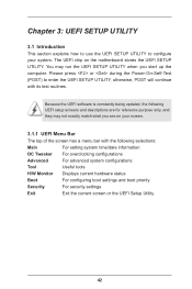
... the following UEFI setup screens and descriptions are for reference purpose only, and they may run the UEFI SETUP UTILITY when you see on the motherboard stores the UEFI SETUP UTILITY. Because the UEFI software is constantly being updated, the following selections: Main For setting system time/date information OC Tweaker...
... the following UEFI setup screens and descriptions are for reference purpose only, and they may run the UEFI SETUP UTILITY when you see on the motherboard stores the UEFI SETUP UTILITY. Because the UEFI software is constantly being updated, the following selections: Main For setting system time/date information OC Tweaker...
User Manual
Page 45
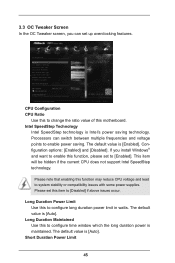
... default value is Intel's power saving technology. Intel SpeedStep Technology Intel SpeedStep technology is [Auto]. The default value is [Auto]. Please note that enabling this motherboard. Please set this to configure time window which the long duration power is maintained. Long Duration Maintained Use this item to [Disabled] if above issues...
... default value is Intel's power saving technology. Intel SpeedStep Technology Intel SpeedStep technology is [Auto]. The default value is [Auto]. Please note that enabling this motherboard. Please set this to configure time window which the long duration power is maintained. Long Duration Maintained Use this item to [Disabled] if above issues...
User Manual
Page 46
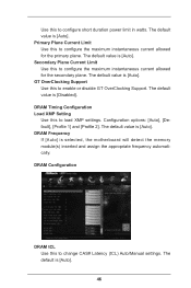
... this to configure the maximum instantaneous current allowed for the primary plane. Configuration options: [Auto], [Default], [Profile 1] and [Profile 2]. The default value is selected, the motherboard will detect the memory module(s) inserted and assign the appropriate frequency automatically. DRAM Frequency If [Auto] is [Auto]. Primary Plane Current Limit Use this to...
... this to configure the maximum instantaneous current allowed for the primary plane. Configuration options: [Auto], [Default], [Profile 1] and [Profile 2]. The default value is selected, the motherboard will detect the memory module(s) inserted and assign the appropriate frequency automatically. DRAM Frequency If [Auto] is [Auto]. Primary Plane Current Limit Use this to...

User Manual
Page 60
... enable or disable the RTC (Real Time Clock) to submit Windows® certification. Please set this option to [Enabled] if you plan to use this motherboard to power on the system. Ring-In Power On Use this to enable or disable the Ring-In signals to turn on the system. USB...
... enable or disable the RTC (Real Time Clock) to submit Windows® certification. Please set this option to [Enabled] if you plan to use this motherboard to power on the system. Ring-In Power On Use this to enable or disable the Ring-In signals to turn on the system. USB...
User Manual
Page 66
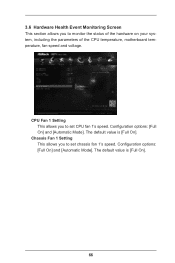
Configuration options: [Full On] and [Automatic Mode]. The default value is [Full On]. The default value is [Full On]. 66 Chassis Fan 1 Setting This allows you to monitor the status of the hardware on your system, including the parameters of the CPU temperature, motherboard temperature, fan speed and voltage. 3.6 Hardware Health Event Monitoring Screen This section allows you to set CPU fan 1's speed. Configuration options: [Full On] and [Automatic Mode]. CPU Fan 1 Setting This allows you to set chassis fan 1's speed.
Configuration options: [Full On] and [Automatic Mode]. The default value is [Full On]. The default value is [Full On]. 66 Chassis Fan 1 Setting This allows you to monitor the status of the hardware on your system, including the parameters of the CPU temperature, motherboard temperature, fan speed and voltage. 3.6 Hardware Health Event Monitoring Screen This section allows you to set CPU fan 1's speed. Configuration options: [Full On] and [Automatic Mode]. CPU Fan 1 Setting This allows you to set chassis fan 1's speed.

