User Manual
Page 5
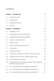
...1 1.1 Package Contents 1 1.2 Specifications 2 1.3 Motherboard Layout 6 1.4 I/O Panel 8 Chapter 2 Installation 9 2.1 Installing the CPU 10 2.2 Installing the CPU Fan and Heatsink 13 2.3 Installing Memory Modules (DIMM) 14 2.4 Expansion Slots (PCIe Slots) 16 2.5 Jumpers Setup 17 2.6 Onboard Headers and Connectors 18 2.7 Smart Button 24 2.8 Post Status Checker 25 2.9 CrossFireXTM and Quad CrossFireXTM Operation Guide 26 2.9.1 Installing Two CrossFireXTM-Ready Graphics Cards 26 2.9.2 Driver Installation and Setup 28 2.10 M.2 WiFi/BT PCIe WiFi Module and Intel®...
...1 1.1 Package Contents 1 1.2 Specifications 2 1.3 Motherboard Layout 6 1.4 I/O Panel 8 Chapter 2 Installation 9 2.1 Installing the CPU 10 2.2 Installing the CPU Fan and Heatsink 13 2.3 Installing Memory Modules (DIMM) 14 2.4 Expansion Slots (PCIe Slots) 16 2.5 Jumpers Setup 17 2.6 Onboard Headers and Connectors 18 2.7 Smart Button 24 2.8 Post Status Checker 25 2.9 CrossFireXTM and Quad CrossFireXTM Operation Guide 26 2.9.1 Installing Two CrossFireXTM-Ready Graphics Cards 26 2.9.2 Driver Installation and Setup 28 2.10 M.2 WiFi/BT PCIe WiFi Module and Intel®...

User Manual
Page 9
... will be updated, the content of the motherboard and step-by-step installation guides. In case any modifications of this motherboard, please visit our website for specific information about the model you for M.2 Sockets (Optional) • 1 x I/O Panel Shield 1 English ASRock website http://www.asrock.com. 1.1 Package Contents • ASRock Z690 Phantom Gaming 4/D5 Motherboard (ATX Form Factor) • ASRock Z690 Phantom Gaming 4/D5 Quick Installation Guide • ASRock Z690 Phantom Gaming 4/D5 Support CD • 2 x Serial ATA (SATA) Data Cables (Optional) • 4 x Screws...
... will be updated, the content of the motherboard and step-by-step installation guides. In case any modifications of this motherboard, please visit our website for specific information about the model you for M.2 Sockets (Optional) • 1 x I/O Panel Shield 1 English ASRock website http://www.asrock.com. 1.1 Package Contents • ASRock Z690 Phantom Gaming 4/D5 Motherboard (ATX Form Factor) • ASRock Z690 Phantom Gaming 4/D5 Quick Installation Guide • ASRock Z690 Phantom Gaming 4/D5 Support CD • 2 x Serial ATA (SATA) Data Cables (Optional) • 4 x Screws...

User Manual
Page 11
... Protection) • 4 x USB 3.2 Gen1 Ports (Supports ESD Protection) • 2 x USB 2.0 Ports (Supports ESD Protection) • 1 x RJ-45 LAN Port with LED (ACT/LINK LED and SPEED LED) • 1 x BIOS Flashback Button • HD Audio Jacks: Line in / Front Speaker / Microphone Storage • 4 x SATA3 6.0 Gb/s Connectors • 1 x Hyper M.2 Socket (M2_1, Key M), supports type 2260/2280 PCIe Gen4x4 (64 Gb/s) mode* • 1 x Hyper M.2 Socket (M2_2, Key M), supports type 2242/2260/2280 PCIe Gen4x4 (64 Gb/s) mode* • 1 x Hyper M.2 Socket (M2_3, Key M), supports type 2260/2280/22110...
... Protection) • 4 x USB 3.2 Gen1 Ports (Supports ESD Protection) • 2 x USB 2.0 Ports (Supports ESD Protection) • 1 x RJ-45 LAN Port with LED (ACT/LINK LED and SPEED LED) • 1 x BIOS Flashback Button • HD Audio Jacks: Line in / Front Speaker / Microphone Storage • 4 x SATA3 6.0 Gb/s Connectors • 1 x Hyper M.2 Socket (M2_1, Key M), supports type 2260/2280 PCIe Gen4x4 (64 Gb/s) mode* • 1 x Hyper M.2 Socket (M2_2, Key M), supports type 2242/2260/2280 PCIe Gen4x4 (64 Gb/s) mode* • 1 x Hyper M.2 Socket (M2_3, Key M), supports type 2260/2280/22110...

User Manual
Page 13
... 2.7 Support • CPU Core/Cache, CPU GT, VDD2, DRAM, VCCIN AUX, +1.8V PROC, +1.05V PROC, +0.82V PCH , +1.05V PCH Voltage Multi-adjustment Hardware Monitor • Fan Tachometer: CPU, CPU/Water Pump, Chassis/Water Pump Fans • Quiet Fan (Auto adjust chassis fan speed by overclocking. English 5 It should be done at your system. Z690 Phantom Gaming 4/D5 BIOS Feature • AMI UEFI Legal BIOS with overclocking, including adjusting the setting in the BIOS, applying Untied Overclocking Technology, or using third-party overclocking...
... 2.7 Support • CPU Core/Cache, CPU GT, VDD2, DRAM, VCCIN AUX, +1.8V PROC, +1.05V PROC, +0.82V PCH , +1.05V PCH Voltage Multi-adjustment Hardware Monitor • Fan Tachometer: CPU, CPU/Water Pump, Chassis/Water Pump Fans • Quiet Fan (Auto adjust chassis fan speed by overclocking. English 5 It should be done at your system. Z690 Phantom Gaming 4/D5 BIOS Feature • AMI UEFI Legal BIOS with overclocking, including adjusting the setting in the BIOS, applying Untied Overclocking Technology, or using third-party overclocking...
User Manual
Page 15
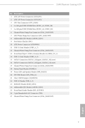
Z690 Phantom Gaming 4/D5 No. Description 1 ATX 12V Power Connector (ATX12V1) 2 ATX 12V Power Connector (ATX12V2) 3 CPU Fan Connector (CPU_FAN1) 4 2 x 288-pin DDR5 DIMM Slots (DDR5_A1, DDR5_B1) 5 2 x 288-pin DDR5 DIMM Slots (DDR5_A2, DDR5_B2) 6 Chassis/Water Pump Fan Connector (CHA_FAN3/WP) 7 CPU/Water Pump Fan Connector (CPU_FAN2/WP) 8 Addressable LED Header (ADDR_LED3) 9 Post Status Checker (PSC) 10 ATX Power Connector (ATXPWR1) 11 USB 3.2 Gen1 Header (USB3_6_7) 12 Chassis/Water Pump Fan Connector (CHA_FAN1/WP) 13 Front Panel Type C USB 3.2 Gen2x2 Header (F_USB32_TC_1) 14 USB 3.2 Gen1 Header ...
Z690 Phantom Gaming 4/D5 No. Description 1 ATX 12V Power Connector (ATX12V1) 2 ATX 12V Power Connector (ATX12V2) 3 CPU Fan Connector (CPU_FAN1) 4 2 x 288-pin DDR5 DIMM Slots (DDR5_A1, DDR5_B1) 5 2 x 288-pin DDR5 DIMM Slots (DDR5_A2, DDR5_B2) 6 Chassis/Water Pump Fan Connector (CHA_FAN3/WP) 7 CPU/Water Pump Fan Connector (CPU_FAN2/WP) 8 Addressable LED Header (ADDR_LED3) 9 Post Status Checker (PSC) 10 ATX Power Connector (ATXPWR1) 11 USB 3.2 Gen1 Header (USB3_6_7) 12 Chassis/Water Pump Fan Connector (CHA_FAN1/WP) 13 Front Panel Type C USB 3.2 Gen2x2 Header (F_USB32_TC_1) 14 USB 3.2 Gen1 Header ...
User Manual
Page 25
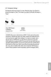
... that the password, date, time, and user default profile will be cleared only if the CMOS battery is "Short". Z690 Phantom Gaming 4/D5 2.5 Jumpers Setup The illustration shows how jumpers are setup. If you do not clear the CMOS right after clearing the CMOS. If no jumper cap is placed on the pins, the jumper is removed. To clear and reset the system parameters to clear the CMOS when you just finish updating the BIOS, you must boot up the...
... that the password, date, time, and user default profile will be cleared only if the CMOS battery is "Short". Z690 Phantom Gaming 4/D5 2.5 Jumpers Setup The illustration shows how jumpers are setup. If you do not clear the CMOS right after clearing the CMOS. If no jumper cap is placed on the pins, the jumper is removed. To clear and reset the system parameters to clear the CMOS when you just finish updating the BIOS, you must boot up the...
User Manual
Page 27
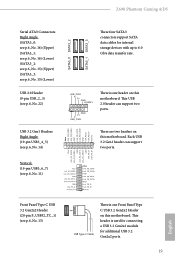
... IntA_PB_DIntA_PB_D+ Dummy 1 Front Panel Type C USB 3.2 Gen2x2 Header (20-pin F_USB32_TC_1) (see p.6, No. 14) Vbus IntA_PB_SSRXIntA_PB_SSRX+ GND IntA_PB_SSTXIntA_PB_SSTX+ GND IntA_PB_DIntA_PB_D+ Dummy SATA3_0 SATA3_2 SATA3_1 SATA3_3 These four SATA3 connectors support SATA data cables for additional USB 3.2 Gen2x2 ports. 19 English This header is used for connecting a USB 3.2 Gen2x2 module for internal storage devices with up to 6.0 Gb/s data transfer rate. This USB 2.0 header can support two ports. Z690 Phantom Gaming 4/D5 Serial ATA3 Connectors Right Angle: (SATA3_0: see...
... IntA_PB_DIntA_PB_D+ Dummy 1 Front Panel Type C USB 3.2 Gen2x2 Header (20-pin F_USB32_TC_1) (see p.6, No. 14) Vbus IntA_PB_SSRXIntA_PB_SSRX+ GND IntA_PB_SSTXIntA_PB_SSTX+ GND IntA_PB_DIntA_PB_D+ Dummy SATA3_0 SATA3_2 SATA3_1 SATA3_3 These four SATA3 connectors support SATA data cables for additional USB 3.2 Gen2x2 ports. 19 English This header is used for connecting a USB 3.2 Gen2x2 module for internal storage devices with up to 6.0 Gb/s data transfer rate. This USB 2.0 header can support two ports. Z690 Phantom Gaming 4/D5 Serial ATA3 Connectors Right Angle: (SATA3_0: see...
User Manual
Page 29
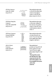
... motherboard provides a 4-Pin CPU fan (Quiet Fan) connector. To use a 20-pin ATX power supply, please plug it along Pin 1 and Pin 13. This motherboard 8 5 provides one 8-pin ATX 12V power connector. To use a 4 1 4-pin ATX power supply, please plug it along Pin 1 and Pin 5. *Warning: Please make sure that the power cable connected is for the CPU and not the graphics card. English 21 If you plan to connect a 3-Pin CPU fan, please connect it to Pin 1-3. 12 24 1 13 This motherboard provides a 24-pin ATX power connector. Do not plug the PCIe power cable...
... motherboard provides a 4-Pin CPU fan (Quiet Fan) connector. To use a 20-pin ATX power supply, please plug it along Pin 1 and Pin 13. This motherboard 8 5 provides one 8-pin ATX 12V power connector. To use a 4 1 4-pin ATX power supply, please plug it along Pin 1 and Pin 5. *Warning: Please make sure that the power cable connected is for the CPU and not the graphics card. English 21 If you plan to connect a 3-Pin CPU fan, please connect it to Pin 1-3. 12 24 1 13 This motherboard provides a 24-pin ATX power connector. Do not plug the PCIe power cable...
User Manual
Page 30
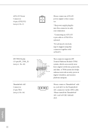
... SPI_CS0 SPI_DQ2 This connector supports SPI Trusted Platform Module (TPM) system, which can securely store keys, digital certificates, passwords, and data. Please connect a Thunderbolt™ addin card (AIC) to the Thunderbolt AIC connector via the GPIO cable. *Please install the Thunderbolt™ AIC card to ATX12V2 is optional. *For advanced overclocking we suggest using this connector in only one orientation. *Connecting an ATX 12V 4-pin cable to PCIE3 (default slot).
... SPI_CS0 SPI_DQ2 This connector supports SPI Trusted Platform Module (TPM) system, which can securely store keys, digital certificates, passwords, and data. Please connect a Thunderbolt™ addin card (AIC) to the Thunderbolt AIC connector via the GPIO cable. *Please install the Thunderbolt™ AIC card to ATX12V2 is optional. *For advanced overclocking we suggest using this connector in only one orientation. *Connecting an ATX 12V 4-pin cable to PCIE3 (default slot).
User Manual
Page 32
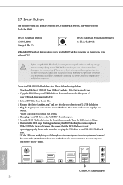
.... Then plug your USB flash drive. Press the BIOS Flashback Switch for several minutes. 2.7 Smart Button The motherboard has a smart button: BIOS Flashback Button, allowing users to disable fTPM before updating the BIOS. Before using the BIOS Flashback function, please suspend BitLocker and any encryption or security relying on the system. 6. Plug the 24 pin power connector to blink. 8. Then the LED starts to the motherboard. Then turn on the power supply's AC switch. *There is recommended to flash the BIOS. Wait...
.... Then plug your USB flash drive. Press the BIOS Flashback Switch for several minutes. 2.7 Smart Button The motherboard has a smart button: BIOS Flashback Button, allowing users to disable fTPM before updating the BIOS. Before using the BIOS Flashback function, please suspend BitLocker and any encryption or security relying on the system. 6. Plug the 24 pin power connector to blink. 8. Then the LED starts to the motherboard. Then turn on the power supply's AC switch. *There is recommended to flash the BIOS. Wait...
User Manual
Page 34
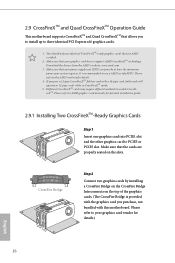
.... 2.9 CrossFireXTM and Quad CrossFireXTM Operation Guide This motherboard supports CrossFireXTM and Quad CrossFireXTM that allows you to install up to the AMD's website for details.) English 26 Make sure that the cards are AMD certified. 2. Please refer to three identical PCI Express x16 graphics cards. 1. Different CrossFireXTM cards may require different methods to use identical CrossFireXTM-ready graphics cards that your graphics card vendor for details. 4. Make...
.... 2.9 CrossFireXTM and Quad CrossFireXTM Operation Guide This motherboard supports CrossFireXTM and Quad CrossFireXTM that allows you to install up to the AMD's website for details.) English 26 Make sure that the cards are AMD certified. 2. Please refer to three identical PCI Express x16 graphics cards. 1. Different CrossFireXTM cards may require different methods to use identical CrossFireXTM-ready graphics cards that your graphics card vendor for details. 4. Make...

User Manual
Page 36
... installed Catalyst drivers prior to your system. Select the GPU number according to installation. Step 5 In the left pane, click Performance and then AMD CrossFireXTM. AMD Catalyst Control Center Step 4 Double-click the AMD Catalyst Control Center icon in your graphics card and click Apply. English 28 The Catalyst Uninstaller is an optional download. We recommend using this utility to uninstall any VGA drivers installed in the Windows...
... installed Catalyst drivers prior to your system. Select the GPU number according to installation. Step 5 In the left pane, click Performance and then AMD CrossFireXTM. AMD Catalyst Control Center Step 4 Double-click the AMD Catalyst Control Center icon in your graphics card and click Apply. English 28 The Catalyst Uninstaller is an optional download. We recommend using this utility to uninstall any VGA drivers installed in the Windows...

User Manual
Page 39
... the corresponding nut location to replace mPCIe and mSATA. Z690 Phantom Gaming 4/D5 2.11 M.2_SSD (NGFF) Module Installation Guide (M2_1) The M.2, also known as the Next Generation Form Factor (NGFF), is a small size and versatile card edge connector that aims to be used. B A No. Nut Location PCB Length Module Type 1 A 6cm Type 2260 2 B 8cm Type 2280 English 31 The Hyper M.2 Socket (M2_1, Key M) supports type 2260/2280 PCIe Gen4x4 (64 Gb...
... the corresponding nut location to replace mPCIe and mSATA. Z690 Phantom Gaming 4/D5 2.11 M.2_SSD (NGFF) Module Installation Guide (M2_1) The M.2, also known as the Next Generation Form Factor (NGFF), is a small size and versatile card edge connector that aims to be used. B A No. Nut Location PCB Length Module Type 1 A 6cm Type 2260 2 B 8cm Type 2280 English 31 The Hyper M.2 Socket (M2_1, Key M) supports type 2260/2280 PCIe Gen4x4 (64 Gb...

User Manual
Page 49
... your system will be auto-detected and listed on the support CD driver page. Drivers Menu The drivers compatible to install those required drivers. Click on the file "ASRSETUP.EXE" in your computer. Z690 Phantom Gaming 4/D5 Chapter 3 Software and Utilities Operation 3.1 Installing Drivers The Support CD that comes with the motherboard contains necessary drivers and useful utilities that the motherboard supports. If the Main Menu does not appear automatically, locate and double click on a specific item then follow the...
... your system will be auto-detected and listed on the support CD driver page. Drivers Menu The drivers compatible to install those required drivers. Click on the file "ASRSETUP.EXE" in your computer. Z690 Phantom Gaming 4/D5 Chapter 3 Software and Utilities Operation 3.1 Installing Drivers The Support CD that comes with the motherboard contains necessary drivers and useful utilities that the motherboard supports. If the Main Menu does not appear automatically, locate and double click on a specific item then follow the...
User Manual
Page 89
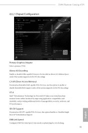
... has SR-IOV capable PCIe Devices, this option to be decoded in Above 4G Address Space (only if the system supports 64 bit PCI decoding). DMI Link Speed Configure DMI Slot Link Speed. Auto mode is optimizing for Directed I/O helps your virtual machine monitor better utilize hardware by improving application compatibility and reliability, and providing additional levels of the system supports 64-bit PCI decoding). 4.6.2 Chipset Configuration Z690 Phantom Gaming 4/D5 Primary Graphics Adapter Select a primary...
... has SR-IOV capable PCIe Devices, this option to be decoded in Above 4G Address Space (only if the system supports 64 bit PCI decoding). DMI Link Speed Configure DMI Slot Link Speed. Auto mode is optimizing for Directed I/O helps your virtual machine monitor better utilize hardware by improving application compatibility and reliability, and providing additional levels of the system supports 64-bit PCI decoding). 4.6.2 Chipset Configuration Z690 Phantom Gaming 4/D5 Primary Graphics Adapter Select a primary...
User Manual
Page 90
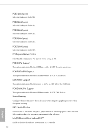
... disable the integrated graphics when an external graphics card is allocated to the integrated graphics processor when the system boots up. IGPU Multi-Monitor Select disable to keep the integrated graphics enabled at all PCH DMI devices. Share Memory Configure the size of the DMI Link. Inte(R) Ethernet Connection I219-V Enable or disable the onboard network interface controller. 82 English PCI Express Native Control Select Enable for all PCH PCIE devices. PCIE ASPM Support This option enables/disables the ASPM support for enhanced PCI Express power...
... disable the integrated graphics when an external graphics card is allocated to the integrated graphics processor when the system boots up. IGPU Multi-Monitor Select disable to keep the integrated graphics enabled at all PCH DMI devices. Share Memory Configure the size of the DMI Link. Inte(R) Ethernet Connection I219-V Enable or disable the onboard network interface controller. 82 English PCI Express Native Control Select Enable for all PCH PCIE devices. PCIE ASPM Support This option enables/disables the ASPM support for enhanced PCI Express power...

User Manual
Page 99
UEFI Tech Service Contact ASRock Tech Service if you can start installing the operating system in your USB storage device and run Instant Flash to update your UEFI. 91 English Instant Flash Save UEFI files in RAID mode. After copying the drivers please change the SATA mode to your PC. Please setup network configuration before using UEFI Tech Service. SSD Secure Erase Tool All the SSD's listed that supports Secure Erase function. Easy RAID Installer Easy RAID Installer helps you Sanitize SSD, all user data...
UEFI Tech Service Contact ASRock Tech Service if you can start installing the operating system in your USB storage device and run Instant Flash to update your UEFI. 91 English Instant Flash Save UEFI files in RAID mode. After copying the drivers please change the SATA mode to your PC. Please setup network configuration before using UEFI Tech Service. SSD Secure Erase Tool All the SSD's listed that supports Secure Erase function. Easy RAID Installer Easy RAID Installer helps you Sanitize SSD, all user data...

User Manual
Page 100
... setup network configuration before using Internet Flash. *For BIOS backup and recovery purpose, it is recommended to plug in the setup utility. UEFI Download Server Select a server to configure internet connection settings for you. Network Configuration Use this function. Internet Setting Enable or disable sound effects in your USB pen drive before using this to download the UEFI firmware. 92 English Internet Flash - DHCP (Auto IP), Auto ASRock Internet Flash downloads and updates the latest UEFI firmware version from our servers for Internet Flash. Intel MEI Flash Starts...
... setup network configuration before using Internet Flash. *For BIOS backup and recovery purpose, it is recommended to plug in the setup utility. UEFI Download Server Select a server to configure internet connection settings for you. Network Configuration Use this function. Internet Setting Enable or disable sound effects in your USB pen drive before using this to download the UEFI firmware. 92 English Internet Flash - DHCP (Auto IP), Auto ASRock Internet Flash downloads and updates the latest UEFI firmware version from our servers for Internet Flash. Intel MEI Flash Starts...
User Manual
Page 105
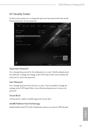
Secure Boot Use this option to enable or disable support for the user account. Disable this item to use discrete TPM Module. 97 English Z690 Phantom Gaming 4/D5 4.9 Security Screen In this section you may also clear the user password. Leave it blank and press enter to remove the password. Users are unable to change the password for Secure Boot. Only the administrator has authority to change the settings in the UEFI Setup Utility. Intel(R) Platform Trust Technology Enable/disable Intel PTT in...
Secure Boot Use this option to enable or disable support for the user account. Disable this item to use discrete TPM Module. 97 English Z690 Phantom Gaming 4/D5 4.9 Security Screen In this section you may also clear the user password. Leave it blank and press enter to remove the password. Users are unable to change the password for Secure Boot. Only the administrator has authority to change the settings in the UEFI Setup Utility. Intel(R) Platform Trust Technology Enable/disable Intel PTT in...

Intel Rapid Storage Guide
Page 13
.... 9. Use the Floppy Configuration Utility to scroll through the list as all controllers may not be prompted Note with the Note necessary files. 4. Use the up and down arrow keys to create a floppy disk with a screen asking you have successfully installed the driver and Windows setup should continue. Select the volume size and press Enter. 8. Press Enter to Specify Additional Device. 3. At the prompt press Y to confirm your exit. Install the RAID Driver Using...
.... 9. Use the Floppy Configuration Utility to scroll through the list as all controllers may not be prompted Note with the Note necessary files. 4. Use the up and down arrow keys to create a floppy disk with a screen asking you have successfully installed the driver and Windows setup should continue. Select the volume size and press Enter. 8. Press Enter to Specify Additional Device. 3. At the prompt press Y to confirm your exit. Install the RAID Driver Using...


