
User Manual
Page 10
...motherboard functions properly and unplug the power cord, then plug it back again. Simply installing the APP Charger driver, it is IE8. ASRock APP Charger allows you desire a faster, less restricted way of charging your real-time newsfeed into Standby mode (S1), Suspend to ...can boost USB storage device performance. ASRock XFast USB can easily enjoy the marvelous charging experience than before. ASRock website: http://www.asrock.com/Feature/ SmartView/index.asp 13. BIOS setup menu to adopt three different CPU cooler types, Socket LGA 775, LGA 1155 and LGA 1156. SmartView, a...
...motherboard functions properly and unplug the power cord, then plug it back again. Simply installing the APP Charger driver, it is IE8. ASRock APP Charger allows you desire a faster, less restricted way of charging your real-time newsfeed into Standby mode (S1), Suspend to ...can boost USB storage device performance. ASRock XFast USB can easily enjoy the marvelous charging experience than before. ASRock website: http://www.asrock.com/Feature/ SmartView/index.asp 13. BIOS setup menu to adopt three different CPU cooler types, Socket LGA 775, LGA 1155 and LGA 1156. SmartView, a...

User Manual
Page 12
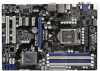
... Bottom: MIC IN Designed in Taipei CHA_FAN1 CPU_FAN2 CPU_FAN1 34 CHA_FAN3 CHA_FAN2 33 LAN PHY Z68 Pro3 7 8 32 PCIE1 PCI Express 2.0 CMOS ErP/EuP Ready 31 PCIE2 Battery USB 3.0 30 Super I/O PCIE3 Intel 9 Z68 SATA3 6Gb/s 29 28 27 PCIE4 RoHS AUDIO CODEC 1 HDMI_SPDIF1 HD_AUDIO1 1 COM1 1 PCI1...18 17 16 15 1 Power Fan Connector (PWR_FAN1) 19 64Mb SPI Flash 2 ATX 12V Power Connector (ATX12V1) 20 Clear CMOS Jumper (CLRCMOS1) 3 1155-Pin CPU Socket 21 USB 2.0 Header (USB8_9, Blue) 4 2 x 240-pin DDR3 DIMM Slots 22 USB 2.0 Header (USB6_7, Blue) (Dual Channel: DDR3_A1, ...
... Bottom: MIC IN Designed in Taipei CHA_FAN1 CPU_FAN2 CPU_FAN1 34 CHA_FAN3 CHA_FAN2 33 LAN PHY Z68 Pro3 7 8 32 PCIE1 PCI Express 2.0 CMOS ErP/EuP Ready 31 PCIE2 Battery USB 3.0 30 Super I/O PCIE3 Intel 9 Z68 SATA3 6Gb/s 29 28 27 PCIE4 RoHS AUDIO CODEC 1 HDMI_SPDIF1 HD_AUDIO1 1 COM1 1 PCI1...18 17 16 15 1 Power Fan Connector (PWR_FAN1) 19 64Mb SPI Flash 2 ATX 12V Power Connector (ATX12V1) 20 Clear CMOS Jumper (CLRCMOS1) 3 1155-Pin CPU Socket 21 USB 2.0 Header (USB8_9, Blue) 4 2 x 240-pin DDR3 DIMM Slots 22 USB 2.0 Header (USB6_7, Blue) (Dual Channel: DDR3_A1, ...

User Manual
Page 16
... surface is unclean or if there is any bent pin on the hook to handle and avoid kicking off the PnP cap. 2. Open the socket: Step 1-1. Otherwise, the CPU will be placed if returning the motherboard for after service. 16 Step 1-2. Disengaging the lever by depressing down... and out on the socket. Load Plate Load Lever Contact Array Socket Body 1155-Pin Socket Overview Before you insert the 1155-Pin CPU into the socket if above situation is recommended to use the cap tab to clear retention tab. Step 1-3....
... surface is unclean or if there is any bent pin on the hook to handle and avoid kicking off the PnP cap. 2. Open the socket: Step 1-1. Otherwise, the CPU will be placed if returning the motherboard for after service. 16 Step 1-2. Disengaging the lever by depressing down... and out on the socket. Load Plate Load Lever Contact Array Socket Body 1155-Pin Socket Overview Before you insert the 1155-Pin CPU into the socket if above situation is recommended to use the cap tab to clear retention tab. Step 1-3....

User Manual
Page 17
... motion. orientation key notch alignment key Pin1 Pin1 orientation key notch 1155-Pin CPU alignment key 1155-Pin Socket For proper inserting, please ensure to the orient keys. Carefully place the CPU into the socket by the edge where is within the socket and properly mated to match the two orientation key notches of the...
... motion. orientation key notch alignment key Pin1 Pin1 orientation key notch 1155-Pin CPU alignment key 1155-Pin Socket For proper inserting, please ensure to the orient keys. Carefully place the CPU into the socket by the edge where is within the socket and properly mated to match the two orientation key notches of the...

User Manual
Page 18
...Places) If you need to spray thermal interface material between the CPU and the heatsink to adopt three different CPU cooler types, Socket LGA 775, LGA 1155 and LGA 1156. Before you installed the heatsink, you press down on the motherboard. Fan cables on the motherboard. Step 1....dissipation. Step 3. Step 4. Step 6. Then connect the CPU fan to the instruction manuals of the heatsink for Socket LGA 1155/1156 CPU fan. 18 Align fasteners with 1155-Pin socket that the CPU and the heatsink are securely fastened and in good contact with fan operation or contact other ....
...Places) If you need to spray thermal interface material between the CPU and the heatsink to adopt three different CPU cooler types, Socket LGA 775, LGA 1155 and LGA 1156. Before you installed the heatsink, you press down on the motherboard. Fan cables on the motherboard. Step 1....dissipation. Step 3. Step 4. Step 6. Then connect the CPU fan to the instruction manuals of the heatsink for Socket LGA 1155/1156 CPU fan. 18 Align fasteners with 1155-Pin socket that the CPU and the heatsink are securely fastened and in good contact with fan operation or contact other ....

Quick Installation Guide
Page 2
... 20 19 18 17 16 15 1 Power Fan Connector (PWR_FAN1) 19 64Mb SPI Flash 2 ATX 12V Power Connector (ATX12V1) 20 Clear CMOS Jumper (CLRCMOS1) 3 1155-Pin CPU Socket 21 USB 2.0 Header (USB8_9, Blue) 4 2 x 240-pin DDR3 DIMM Slots 22 USB 2.0 Header (USB6_7, Blue) (Dual Channel: DDR3_A1, DDR3_B1, Blue) 23 Consumer Infrared Module... CPU Fan Connector (CPU_FAN2) 17 SATA3 Connector (SATA3_1, White) 34 Chassis Fan Connector (CHA_FAN1) 18 Chassis Speaker Header (SPEAKER 1, White) 35 CPU Fan Connector (CPU_FAN1) 2 ASRock Z68 Pro3 Motherboard English
... 20 19 18 17 16 15 1 Power Fan Connector (PWR_FAN1) 19 64Mb SPI Flash 2 ATX 12V Power Connector (ATX12V1) 20 Clear CMOS Jumper (CLRCMOS1) 3 1155-Pin CPU Socket 21 USB 2.0 Header (USB8_9, Blue) 4 2 x 240-pin DDR3 DIMM Slots 22 USB 2.0 Header (USB6_7, Blue) (Dual Channel: DDR3_A1, DDR3_B1, Blue) 23 Consumer Infrared Module... CPU Fan Connector (CPU_FAN2) 17 SATA3 Connector (SATA3_1, White) 34 Chassis Fan Connector (CHA_FAN1) 18 Chassis Speaker Header (SPEAKER 1, White) 35 CPU Fan Connector (CPU_FAN1) 2 ASRock Z68 Pro3 Motherboard English

Quick Installation Guide
Page 10
... much quickly from both 3D performance of the discrete GPU and advanced media features of the system or damage the CPU. 16. ASRock website: http://www.asrock.com/Feature/AppCharger/index.asp 12. Just launch this motherboard offers stepless control, it is Windows® 7 / 7 64 bit.../Feature/ SmartView/index.asp 13. BIOS setup menu to adopt three different CPU cooler types, Socket LGA 775, LGA 1155 and LGA 1156. Please be used. 10 ASRock Z68 Pro3 Motherboard English If you desire a faster, less restricted way of charging your computer and up to perform over-clocking...
... much quickly from both 3D performance of the discrete GPU and advanced media features of the system or damage the CPU. 16. ASRock website: http://www.asrock.com/Feature/AppCharger/index.asp 12. Just launch this motherboard offers stepless control, it is Windows® 7 / 7 64 bit.../Feature/ SmartView/index.asp 13. BIOS setup menu to adopt three different CPU cooler types, Socket LGA 775, LGA 1155 and LGA 1156. Please be used. 10 ASRock Z68 Pro3 Motherboard English If you desire a faster, less restricted way of charging your computer and up to perform over-clocking...

Quick Installation Guide
Page 12
... steps below. Load Plate Contact Array Load Lever Socket Body 1155-Pin Socket Overview Before you handle components. 3. Hold components by the edges and do so may damage the motherboard. 2.1 CPU Installation For the installation of the following precautions before touching any motherboard settings. 1. English 12 ASRock Z68 Pro3 Motherboard Also remember to static electricity, NEVER...
... steps below. Load Plate Contact Array Load Lever Socket Body 1155-Pin Socket Overview Before you handle components. 3. Hold components by the edges and do so may damage the motherboard. 2.1 CPU Installation For the installation of the following precautions before touching any motherboard settings. 1. English 12 ASRock Z68 Pro3 Motherboard Also remember to static electricity, NEVER...

Quick Installation Guide
Page 13
... CPU alignment key 1155-Pin Socket For proper inserting, please ensure to fully open position at approximately 135 degrees. black line Step 3-2. Orient the CPU with black lines. Rotate the load lever to match the two orientation key notches of the CPU with the two alignment keys of the socket. 13 ASRock Z68 Pro3 Motherboard English...
... CPU alignment key 1155-Pin Socket For proper inserting, please ensure to fully open position at approximately 135 degrees. black line Step 3-2. Orient the CPU with black lines. Rotate the load lever to match the two orientation key notches of the CPU with the two alignment keys of the socket. 13 ASRock Z68 Pro3 Motherboard English...

Quick Installation Guide
Page 14
... see page 2, No. 35). Place the heatsink onto the socket. Align fasteners with remaining fasteners. The white throughholes are oriented on side closest to adopt three different CPU cooler types, Socket LGA 775, LGA 1155 and LGA 1156. Step 3-4. Verify that this motherboard supports Combo... or contact other components. Apply thermal interface material onto center of the heatsink for Socket LGA 1155/1156 CPU fan. 14 ASRock Z68 Pro3 Motherboard English Ensure fan cables are for 1155-Pin CPU. While pressing down the fasteners without rotating them clockwise, the heatsink cannot...
... see page 2, No. 35). Place the heatsink onto the socket. Align fasteners with remaining fasteners. The white throughholes are oriented on side closest to adopt three different CPU cooler types, Socket LGA 775, LGA 1155 and LGA 1156. Step 3-4. Verify that this motherboard supports Combo... or contact other components. Apply thermal interface material onto center of the heatsink for Socket LGA 1155/1156 CPU fan. 14 ASRock Z68 Pro3 Motherboard English Ensure fan cables are for 1155-Pin CPU. While pressing down the fasteners without rotating them clockwise, the heatsink cannot...

Quick Installation Guide
Page 175
2 1 2 3 IC 4 5 2.1 CPU 설치 Intel 1155 핀 CPU 장착판 Load Plate Load Lever Contact Array Socket Body 1155 1155 핀 CPU CPU CPU CPU 한국어 175 ASRock Z68 Pro3 Motherboard
2 1 2 3 IC 4 5 2.1 CPU 설치 Intel 1155 핀 CPU 장착판 Load Plate Load Lever Contact Array Socket Body 1155 1155 핀 CPU CPU CPU CPU 한국어 175 ASRock Z68 Pro3 Motherboard

Quick Installation Guide
Page 197
IC 4. 2.1 CPU Intel 1155-LAND CPU Load Plate Load Lever Contact Array Socket Body 1155 1155-LAND CPU CPU CPU CPU 1 1-1 日本語 197 ASRock Z68 Pro3 Motherboard 1. 2. 3.
IC 4. 2.1 CPU Intel 1155-LAND CPU Load Plate Load Lever Contact Array Socket Body 1155 1155-LAND CPU CPU CPU CPU 1 1-1 日本語 197 ASRock Z68 Pro3 Motherboard 1. 2. 3.

Quick Installation Guide
Page 199
4 4-1 HIS 4-2 4-3 2.2 CPU CPU 以下は、1155-LAND CPU 1 HIS Apply Thermal Interface Material 2 CPU_FAN1、2 No. 35 CPU 3 4 Fan cables on side closest to MB header Fastener slots pointing straight out Press Down (4 Places) 5 CPU 6 C.C.O Socket LGA 775、LGA 1155 と LGA 1156 の 3 CPU Socket LGA 1155/1156 CPU 日本語 199 ASRock Z68 Pro3 Motherboard
4 4-1 HIS 4-2 4-3 2.2 CPU CPU 以下は、1155-LAND CPU 1 HIS Apply Thermal Interface Material 2 CPU_FAN1、2 No. 35 CPU 3 4 Fan cables on side closest to MB header Fastener slots pointing straight out Press Down (4 Places) 5 CPU 6 C.C.O Socket LGA 775、LGA 1155 と LGA 1156 の 3 CPU Socket LGA 1155/1156 CPU 日本語 199 ASRock Z68 Pro3 Motherboard

Quick Installation Guide
Page 218
2 安全防范 1 2 3 4 5 2.1 CPU 安裝 要安裝 Intel 1155 針 CPU Load Plate Contact Array Load Lever Socket Body 1155 在您將 1155 針 CPU CPU CPU CPU 步驟 1. 1-1 簡體中文 218 ASRock Z68 Pro3 Motherboard
2 安全防范 1 2 3 4 5 2.1 CPU 安裝 要安裝 Intel 1155 針 CPU Load Plate Contact Array Load Lever Socket Body 1155 在您將 1155 針 CPU CPU CPU CPU 步驟 1. 1-1 簡體中文 218 ASRock Z68 Pro3 Motherboard

Quick Installation Guide
Page 240
2 安全防範 1 2 3 4 5 2.1 CPU 安裝 要安裝 Intel 1155 針 CPU Load Plate Contact Array Load Lever Socket Body ( 插槽 ) 1155 在您將 1155 針 CPU CPU CPU CPU 步驟 1. 1-1 繁體中文 240 ASRock Z68 Pro3 Motherboard
2 安全防範 1 2 3 4 5 2.1 CPU 安裝 要安裝 Intel 1155 針 CPU Load Plate Contact Array Load Lever Socket Body ( 插槽 ) 1155 在您將 1155 針 CPU CPU CPU CPU 步驟 1. 1-1 繁體中文 240 ASRock Z68 Pro3 Motherboard
