
Intel Rapid Storage Guide
Page 12
... BIOS settings and exit the BIOS Setup program. Click F10 to select the drive. Enable RAID in System BIOS Use the instructions included with your motherboard to enable RAID in the system BIOS, a RAID volume must be created, and the F6 installation method must be enabled in the system BIOS...
... BIOS settings and exit the BIOS Setup program. Click F10 to select the drive. Enable RAID in System BIOS Use the instructions included with your motherboard to enable RAID in the system BIOS, a RAID volume must be created, and the F6 installation method must be enabled in the system BIOS...

Intel Smart Response Installation Guide
Page 1
Intel Smart Response Technology Installation Guide This motherboard supports Intel Smart Response Technology. You can find the UI setup instruction and the step by double-clicking RST Storage icon in system at this ... system, then install all performance testing, chose "Maximized" mode. 7. For the new version RST driver, please check our website for the latest information: http://www.asrock.com * Before you use Enhanced or Maximized Mode. 6. For all required drivers, including RST storage driver version 10.5 or later. 2. After clicking OK button, SRT...
Intel Smart Response Technology Installation Guide This motherboard supports Intel Smart Response Technology. You can find the UI setup instruction and the step by double-clicking RST Storage icon in system at this ... system, then install all performance testing, chose "Maximized" mode. 7. For the new version RST driver, please check our website for the latest information: http://www.asrock.com * Before you use Enhanced or Maximized Mode. 6. For all required drivers, including RST storage driver version 10.5 or later. 2. After clicking OK button, SRT...

User Manual
Page 2
... conditions: (1) this device may cause undesired operation. Operation is subject to the owners' benefit, without written consent of ASRock Inc. When you discard the Lithium battery in California, USA, please follow the related regulations in Perchlorate Best Management Practices (...any kind, either expressed or implied, including but not limited to infringe. ASRock assumes no event shall ASRock, its directors, of the FCC Rules. Products and corporate names appearing in this motherboard contains Perchlorate, a toxic substance controlled in advance. CALIFORNIA, USA ONLY The...
... conditions: (1) this device may cause undesired operation. Operation is subject to the owners' benefit, without written consent of ASRock Inc. When you discard the Lithium battery in California, USA, please follow the related regulations in Perchlorate Best Management Practices (...any kind, either expressed or implied, including but not limited to infringe. ASRock assumes no event shall ASRock, its directors, of the FCC Rules. Products and corporate names appearing in this motherboard contains Perchlorate, a toxic substance controlled in advance. CALIFORNIA, USA ONLY The...

User Manual
Page 3
... 5 1.2 Specifications 6 1.3 Motherboard Layout 12 1.4 I/O Panel 13 2 Installation 15 2.1 Screw Holes 15 2.2 Pre-installation Precautions 15 2.3 CPU Installation 16 2.4 Installation of Heatsink and CPU fan 18 2.5 Installation of Memory Modules (DIMM 19 2.6 Expansion Slots (PCI and PCI Express Slots 21 2.7 Dual Monitor and Surround Display Features 22 2.8 ASRock Smart Remote Installation...
... 5 1.2 Specifications 6 1.3 Motherboard Layout 12 1.4 I/O Panel 13 2 Installation 15 2.1 Screw Holes 15 2.2 Pre-installation Precautions 15 2.3 CPU Installation 16 2.4 Installation of Heatsink and CPU fan 18 2.5 Installation of Memory Modules (DIMM 19 2.6 Expansion Slots (PCI and PCI Express Slots 21 2.7 Dual Monitor and Surround Display Features 22 2.8 ASRock Smart Remote Installation...

User Manual
Page 5
... x 21.1 cm) ASRock Z68 Pro3 Quick Installation Guide ASRock Z68 Pro3 Support CD 2 x Serial ATA (SATA) Data Cables (Optional) 1 x I/O Panel Shield ASRock Reminds You... www.asrock.com/support/index.asp 1.1 Package Contents ASRock Z68 Pro3 Motherboard (ATX Form Factor: 12.0-in x 8.3-in Storage Configuration to the "User Manual" in our support CD for purchasing ASRock Z68 Pro3 motherboard, a reliable motherboard produced under ASRock's consistently stringent quality...
... x 21.1 cm) ASRock Z68 Pro3 Quick Installation Guide ASRock Z68 Pro3 Support CD 2 x Serial ATA (SATA) Data Cables (Optional) 1 x I/O Panel Shield ASRock Reminds You... www.asrock.com/support/index.asp 1.1 Package Contents ASRock Z68 Pro3 Motherboard (ATX Form Factor: 12.0-in x 8.3-in Storage Configuration to the "User Manual" in our support CD for purchasing ASRock Z68 Pro3 motherboard, a reliable motherboard produced under ASRock's consistently stringent quality...

User Manual
Page 9
... update tool allows you are allowed to use two of the three monitors only. About the setting of ASRock Extreme Tuning Utility (AXTU). For audio output, this motherboard supports both stereo and mono modes. In Fan Control, it shows the major readings of output phases to...the latest information. 6. Please check the table on the processor. This motherboard supports Dual Channel Memory Technology. Before you to improve efficiency when the CPU cores are only supported under Windows® 7 / VistaTM / XP. ASRock Extreme Tuning Utility (AXTU) is subject to 2133 and 1866. 4. ...
... update tool allows you are allowed to use two of the three monitors only. About the setting of ASRock Extreme Tuning Utility (AXTU). For audio output, this motherboard supports both stereo and mono modes. In Fan Control, it shows the major readings of output phases to...the latest information. 6. Please check the table on the processor. This motherboard supports Dual Channel Memory Technology. Before you to improve efficiency when the CPU cores are only supported under Windows® 7 / VistaTM / XP. ASRock Extreme Tuning Utility (AXTU) is subject to 2133 and 1866. 4. ...

User Manual
Page 10
...your real-time newsfeed into Standby mode (S1), Suspend to perform over-clocking. ASRock motherboards are exclusively equipped with friends on the property of the system or damage the CPU. 16. ASRock XFast USB can enjoy benefits from your computer and up to your ...64258;ash utility. Combo Cooler Option (C.C.O.) provides the flexible option to access ASRock Instant Flash. Please be noted that helps you can boost USB storage device performance. Just launch this motherboard offers stepless control, it makes your iPhone charged much quickly from both 3D performance...
...your real-time newsfeed into Standby mode (S1), Suspend to perform over-clocking. ASRock motherboards are exclusively equipped with friends on the property of the system or damage the CPU. 16. ASRock XFast USB can enjoy benefits from your computer and up to your ...64258;ash utility. Combo Cooler Option (C.C.O.) provides the flexible option to access ASRock Instant Flash. Please be noted that helps you can boost USB storage device performance. Just launch this motherboard offers stepless control, it makes your iPhone charged much quickly from both 3D performance...

User Manual
Page 11
... for Energy Using Product, was a provision regulated by European Union to Intel's suggestion, the EuP ready power supply must meet EuP standard, an EuP ready motherboard and an EuP ready power supply are required. According to EuP, the total AC power of 5v standby power efficiency is higher than...
... for Energy Using Product, was a provision regulated by European Union to Intel's suggestion, the EuP ready power supply must meet EuP standard, an EuP ready motherboard and an EuP ready power supply are required. According to EuP, the total AC power of 5v standby power efficiency is higher than...

User Manual
Page 12
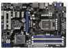
1.3 Motherboard Layout PS2 Keyboard USB 2.0 T: USB0 B: USB1 1 2 3 21.1cm (8.3 in) ...Taipei CHA_FAN1 CPU_FAN2 CPU_FAN1 34 CHA_FAN3 CHA_FAN2 33 LAN PHY Z68 Pro3 7 8 32 PCIE1 PCI Express 2.0 CMOS ErP/EuP Ready 31 PCIE2 Battery USB 3.0 30 Super I/O PCIE3 Intel 9 Z68 SATA3 6Gb/s 29 28 27 PCIE4 RoHS AUDIO CODEC ...7 Chassis Fan Connector (CHA_FAN2) 26 Front Panel Audio Header 8 Chassis Fan Connector (CHA_FAN3) (HD_AUDIO1, White) 9 Intel Z68 Chipset 27 HDMI_SPDIF Header 10 SATA3 Connector (SATA3_0, White) (HDMI_SPDIF1, White) 11 SATA2 Connector (SATA2_2, Blue) 28 PCI...
1.3 Motherboard Layout PS2 Keyboard USB 2.0 T: USB0 B: USB1 1 2 3 21.1cm (8.3 in) ...Taipei CHA_FAN1 CPU_FAN2 CPU_FAN1 34 CHA_FAN3 CHA_FAN2 33 LAN PHY Z68 Pro3 7 8 32 PCIE1 PCI Express 2.0 CMOS ErP/EuP Ready 31 PCIE2 Battery USB 3.0 30 Super I/O PCIE3 Intel 9 Z68 SATA3 6Gb/s 29 28 27 PCIE4 RoHS AUDIO CODEC ...7 Chassis Fan Connector (CHA_FAN2) 26 Front Panel Audio Header 8 Chassis Fan Connector (CHA_FAN3) (HD_AUDIO1, White) 9 Intel Z68 Chipset 27 HDMI_SPDIF Header 10 SATA3 Connector (SATA3_0, White) (HDMI_SPDIF1, White) 11 SATA2 Connector (SATA2_2, Blue) 28 PCI...

User Manual
Page 15
.... 3. Failure to do not touch the ICs. 4. Unplug the power cord from the power supply. Whenever you uninstall any component. 2. Before you install motherboard components or change any component, ensure that the power is switched off or the power cord is an ATX form factor (12.0" x 8.3", 30.5 x 21...from the wall socket before touching any component, place it . Do not over-tighten the screws! Hold components by circles to secure the motherboard to ensure that comes with the component. Make sure to use a grounded wrist strap or touch a safety grounded object before installing or removing...
.... 3. Failure to do not touch the ICs. 4. Unplug the power cord from the power supply. Whenever you uninstall any component. 2. Before you install motherboard components or change any component, ensure that the power is switched off or the power cord is an ATX form factor (12.0" x 8.3", 30.5 x 21...from the wall socket before touching any component, place it . Do not over-tighten the screws! Hold components by circles to secure the motherboard to ensure that comes with the component. Make sure to use a grounded wrist strap or touch a safety grounded object before installing or removing...

User Manual
Page 16
... is any bent pin on the hook to fully open position at approximately 100 degrees. Step 1-2. Otherwise, the CPU will be placed if returning the motherboard for after service. 16 Load Plate Load Lever Contact Array Socket Body 1155-Pin Socket Overview Before you insert the 1155-Pin CPU into the...
... is any bent pin on the hook to fully open position at approximately 100 degrees. Step 1-2. Otherwise, the CPU will be placed if returning the motherboard for after service. 16 Load Plate Load Lever Contact Array Socket Body 1155-Pin Socket Overview Before you insert the 1155-Pin CPU into the...

User Manual
Page 18
.... Ensure that supports Intel 1155-Pin CPU. Repeat with Intel 1155Pin CPU to dissipate heat. Fan cables on fastener caps with the motherboard throughholes. Apply thermal interface material onto center of your CPU fan and heatsink. Place the heatsink onto the socket. Align fasteners with ...thumb to install and lock. Apply Thermal Interface Material Step 2. 2.4 Installation of CPU Fan and Heatsink This motherboard is an example to illustrate the installation of the heatsink for Socket LGA 1155/1156 CPU fan. 18 Step 3. Ensure fan cables are...
.... Ensure that supports Intel 1155-Pin CPU. Repeat with Intel 1155Pin CPU to dissipate heat. Fan cables on fastener caps with the motherboard throughholes. Apply thermal interface material onto center of your CPU fan and heatsink. Place the heatsink onto the socket. Align fasteners with ...thumb to install and lock. Apply Thermal Interface Material Step 2. 2.4 Installation of CPU Fan and Heatsink This motherboard is an example to illustrate the installation of the heatsink for Socket LGA 1155/1156 CPU fan. 18 Step 3. Ensure fan cables are...

User Manual
Page 19
...pair in the slots of the same color. see p.12 No.4) or identical DDR3 DIMM pair in the slots of the same color. This motherboard also allows you want to install two memory modules, for dual channel configuration, and please install identical DDR3 DIMMs in DDR3_A1 and DDR3_A2... Configuration Table below. White slots; If only one memory module or three memory modules are installed in the DDR3 DIMM slots on this motherboard, it is not recommended to activate the Dual Channel Memory Technology . 4. For dual channel configuration, you have to install a DDR or DDR2...
...pair in the slots of the same color. see p.12 No.4) or identical DDR3 DIMM pair in the slots of the same color. This motherboard also allows you want to install two memory modules, for dual channel configuration, and please install identical DDR3 DIMMs in DDR3_A1 and DDR3_A2... Configuration Table below. White slots; If only one memory module or three memory modules are installed in the DDR3 DIMM slots on this motherboard, it is not recommended to activate the Dual Channel Memory Technology . 4. For dual channel configuration, you have to install a DDR or DDR2...

User Manual
Page 20
.... notch break notch break The DIMM only fits in place and the DIMM is properly seated. 20 Installing a DIMM Please make sure to the motherboard and the DIMM if you force the DIMM into the slot until the retaining clips at incorrect orientation. Step 3. Step 2. It will cause permanent damage...
.... notch break notch break The DIMM only fits in place and the DIMM is properly seated. 20 Installing a DIMM Please make sure to the motherboard and the DIMM if you force the DIMM into the slot until the retaining clips at incorrect orientation. Step 3. Step 2. It will cause permanent damage...

User Manual
Page 21
... hardware settings for PCI Express cards with the slot and press firmly until the card is completely seated on this motherboard. Step 2. Remove the system unit cover (if your motherboard is used to install expansion cards that you start the installation. Step 4. Align the card connector with x1 lane width cards...
... hardware settings for PCI Express cards with the slot and press firmly until the card is completely seated on this motherboard. Step 2. Remove the system unit cover (if your motherboard is used to install expansion cards that you start the installation. Step 4. Align the card connector with x1 lane width cards...

User Manual
Page 22
...enjoy the benefits of dual monitor function after your computer. 2.7 Dual Monitor and Surround Display Features Dual Monitor Feature This motherboard supports dual monitor feature. You can drive same or different display contents. To enable dual monitor feature, please follow the below steps: ...cable to VGA/D-Sub port on the I /O panel. D-Sub, DVI-D and HDMI monitors cannot be enabled at the same time. This motherboard also provides independent display controllers for DVI-D, D-Sub and HDMI to your system and restart your system boots. With the internal VGA output support ...
...enjoy the benefits of dual monitor function after your computer. 2.7 Dual Monitor and Surround Display Features Dual Monitor Feature This motherboard supports dual monitor feature. You can drive same or different display contents. To enable dual monitor feature, please follow the below steps: ...cable to VGA/D-Sub port on the I /O panel. D-Sub, DVI-D and HDMI monitors cannot be enabled at the same time. This motherboard also provides independent display controllers for DVI-D, D-Sub and HDMI to your system and restart your system boots. With the internal VGA output support ...

User Manual
Page 23
.... Then connect other monitor cables to apply these new values. Boot your system. Click "Extend my Windows desktop onto this motherboard. 4. Set up a surround display environment: 1. A. Surround Display Feature This motherboard supports surround display upgrade. Please make sure that the value you can easily enjoy the benefits of "Onboard VGA...
.... Then connect other monitor cables to apply these new values. Boot your system. Click "Extend my Windows desktop onto this motherboard. 4. Set up a surround display environment: 1. A. Surround Display Feature This motherboard supports surround display upgrade. Please make sure that the value you can easily enjoy the benefits of "Onboard VGA...

User Manual
Page 24
... projector. Due to the increase in manufacturers employing HDCP in their equipment, it is my main monitor" and "Extend the desktop onto this motherboard, you need to a compliant display. B. C. Use Surround Display. In other words, HDCP specification is designed to eliminate the ...possibility of content as it is highly recommended that the HDTV or LCD monitor you purchase is supported on this motherboard. Click the items "This is being transmitted. D. such as well. What is a copy protection scheme to protect the integrity of...
... projector. Due to the increase in manufacturers employing HDCP in their equipment, it is my main monitor" and "Extend the desktop onto this motherboard, you need to a compliant display. B. C. Use Surround Display. In other words, HDCP specification is designed to eliminate the ...possibility of content as it is highly recommended that the HDTV or LCD monitor you purchase is supported on this motherboard. Click the items "This is being transmitted. D. such as well. What is a copy protection scheme to protect the integrity of...

User Manual
Page 25
...support Hot-Plug function. Multi-Angle CIR Receiver is compatible with CIR header. Please refer to connect it on ASRock motherboard. Please make sure the wire assignments and the PP+ GND DUMMY pin assignments are matched correctly. 1 23 45 Step3. Only ...direction infrared signals (top, down and front), which is used for ASRock motherboard with most of ASRock motherboards. Please refer to the USB_PWR USB 2.0 header (as below procedures for the motherboard support list: http://www.asrock.com 25 If Multi-Angle CIR Receiver cannot successfully receive the infrared ...
...support Hot-Plug function. Multi-Angle CIR Receiver is compatible with CIR header. Please refer to connect it on ASRock motherboard. Please make sure the wire assignments and the PP+ GND DUMMY pin assignments are matched correctly. 1 23 45 Step3. Only ...direction infrared signals (top, down and front), which is used for ASRock motherboard with most of ASRock motherboards. Please refer to the USB_PWR USB 2.0 header (as below procedures for the motherboard support list: http://www.asrock.com 25 If Multi-Angle CIR Receiver cannot successfully receive the infrared ...

User Manual
Page 27
... p.12, No. 14) SATA2_2 SATA2_3 SATA2_4 SATA2_5 These four Serial ATAII (SATAII) connectors support SATA data cables for internal storage devices. Either end of the motherboard! The current SATA3 interface allows up to the SATA / SATAII / SATA3 hard disk or the SATAII / SATA3 connector on this...
... p.12, No. 14) SATA2_2 SATA2_3 SATA2_4 SATA2_5 These four Serial ATAII (SATAII) connectors support SATA data cables for internal storage devices. Either end of the motherboard! The current SATA3 interface allows up to the SATA / SATAII / SATA3 hard disk or the SATAII / SATA3 connector on this...


