Intel Rapid Storage Guide
Page 12
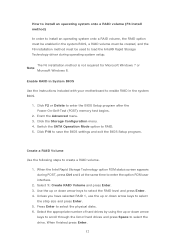
... the BIOS Setup program after the Power-On-Self-Test (POST) memory test begins. 2. Enable RAID in System BIOS Use the instructions included with your motherboard to save the BIOS settings and exit the BIOS Setup program. Click the Storage Configuration menu. 4. Click F10 to enable RAID in the system BIOS...
... the BIOS Setup program after the Power-On-Self-Test (POST) memory test begins. 2. Enable RAID in System BIOS Use the instructions included with your motherboard to save the BIOS settings and exit the BIOS Setup program. Click the Storage Configuration menu. 4. Click F10 to enable RAID in the system BIOS...
RAID Installation Guide
Page 2
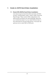
Please read the RAID configurations in this motherboard for internal storage devices. You may install SATA hard disks on SATA ports. 2 This section will guide you how to create RAID on this guide carefully according to SATA Hard Disks Installation 1.1 Serial ATA (SATA) Hard Disks Installation Intel chipset supports Serial ATA (SATA) hard disks with RAID functions, including RAID 0, RAID 1, RAID 5, RAID 10 and Intel Rapid Storage. Guide to the Intel southbridge chipset that your motherboard adopts. 1.
Please read the RAID configurations in this motherboard for internal storage devices. You may install SATA hard disks on SATA ports. 2 This section will guide you how to create RAID on this guide carefully according to SATA Hard Disks Installation 1.1 Serial ATA (SATA) Hard Disks Installation Intel chipset supports Serial ATA (SATA) hard disks with RAID functions, including RAID 0, RAID 1, RAID 5, RAID 10 and Intel Rapid Storage. Guide to the Intel southbridge chipset that your motherboard adopts. 1.
RAID Installation Guide
Page 3
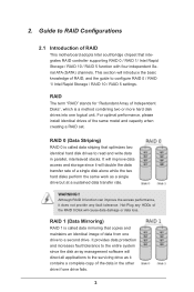
... The term "RAID" stands for "Redundant Array of the same model and capacity when creating a RAID set. Guide to RAID Configurations 2.1 Introduction of RAID This motherboard adopts Intel southbridge chipset that copies and maintains an identical image of RAID, and the guide to a second drive. It will improve data access and...
... The term "RAID" stands for "Redundant Array of the same model and capacity when creating a RAID set. Guide to RAID Configurations 2.1 Introduction of RAID This motherboard adopts Intel southbridge chipset that copies and maintains an identical image of RAID, and the guide to a second drive. It will improve data access and...
RAID Installation Guide
Page 23
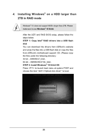
... 64-bit. STEP 1: Copy Intel® RAID drivers into a USB flash disk You can download the drivers from ASRock's website and unzip the files into a USB flash disk or copy the files from ASRock's motherboard support CD. (Please copy the files under the following directory: 32 bit: ..\i386\Win7_Intel.. 64-bit: ..\AMD64\Win7...
... 64-bit. STEP 1: Copy Intel® RAID drivers into a USB flash disk You can download the drivers from ASRock's website and unzip the files into a USB flash disk or copy the files from ASRock's motherboard support CD. (Please copy the files under the following directory: 32 bit: ..\i386\Win7_Intel.. 64-bit: ..\AMD64\Win7...
RAID Installation Guide
Page 25
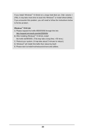
E. Disk volume > 2TB), it may take more time to install motherboard drivers and utilities. 25 Windows® 10 64-bit: A. Please request the hotfix KB2505454 through this link: http://support.microsoft.com/kb/2505454/ B. After installing ...
E. Disk volume > 2TB), it may take more time to install motherboard drivers and utilities. 25 Windows® 10 64-bit: A. Please request the hotfix KB2505454 through this link: http://support.microsoft.com/kb/2505454/ B. After installing ...
User Manual
Page 2
... errors or omissions that may apply, see www.dtsc.ca.gov/hazardouswaste/ perchlorate" ASRock Website: http://www.asrock.com CALIFORNIA, USA ONLY The Lithium battery adopted on this motherboard contains Perchlorate, a toxic substance controlled in this documentation may be constructed as a ...commitment by ASRock. Version 1.1 Published September 2018 Copyright©2018 ASRock INC. Products and corporate names appearing in this device...
... errors or omissions that may apply, see www.dtsc.ca.gov/hazardouswaste/ perchlorate" ASRock Website: http://www.asrock.com CALIFORNIA, USA ONLY The Lithium battery adopted on this motherboard contains Perchlorate, a toxic substance controlled in this documentation may be constructed as a ...commitment by ASRock. Version 1.1 Published September 2018 Copyright©2018 ASRock INC. Products and corporate names appearing in this device...
User Manual
Page 5
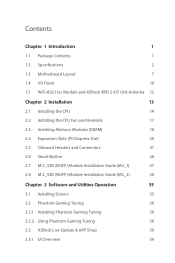
Contents Chapter 1 Introduction 1 1.1 Package Contents 1 1.2 Specifications 2 1.3 Motherboard Layout 7 1.4 I/O Panel 10 1.5 WiFi-802.11ac Module and ASRock WiFi 2.4/5 GHz Antenna 12 Chapter 2 Installation 13 2.1 Installing the CPU 14 2.2 Installing the CPU Fan and Heatsink...27 2.8 M.2_SSD (NGFF) Module Installation Guide (M2_2) 30 Chapter 3 Software and Utilities Operation 35 3.1 Installing Drivers 35 3.2 Phantom Gaming Tuning 36 3.2.1 Installing Phantom Gaming Tuning 36 3.2.2 Using Phantom Gaming Tuning 36 3.3 ASRock Live Update & APP Shop 39 3.3.1 UI Overview 39
Contents Chapter 1 Introduction 1 1.1 Package Contents 1 1.2 Specifications 2 1.3 Motherboard Layout 7 1.4 I/O Panel 10 1.5 WiFi-802.11ac Module and ASRock WiFi 2.4/5 GHz Antenna 12 Chapter 2 Installation 13 2.1 Installing the CPU 14 2.2 Installing the CPU Fan and Heatsink...27 2.8 M.2_SSD (NGFF) Module Installation Guide (M2_2) 30 Chapter 3 Software and Utilities Operation 35 3.1 Installing Drivers 35 3.2 Phantom Gaming Tuning 36 3.2.1 Installing Phantom Gaming Tuning 36 3.2.2 Using Phantom Gaming Tuning 36 3.3 ASRock Live Update & APP Shop 39 3.3.1 UI Overview 39
User Manual
Page 8
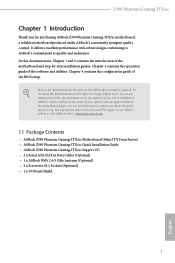
...website http://www.asrock.com. 1.1 Package Contents • ASRock Z390 Phantom Gaming-ITX/ac Motherboard (Mini-ITX Form Factor) • ASRock Z390 Phantom Gaming-ITX/ac Quick Installation Guide • ASRock Z390 Phantom Gaming-ITX/ac Support CD • 2 x Serial ATA (SATA) Data Cables (Optional) • 1 x ASRock WiFi 2.4/5 GHz Antenna (Optional) • 2 x Screws for purchasing ASRock Z390 Phantom Gaming-ITX/ac motherboard, a reliable motherboard produced under ASRock's consistently stringent quality control. In case any modifications of this documentation, Chapter 1 and 2 contains...
...website http://www.asrock.com. 1.1 Package Contents • ASRock Z390 Phantom Gaming-ITX/ac Motherboard (Mini-ITX Form Factor) • ASRock Z390 Phantom Gaming-ITX/ac Quick Installation Guide • ASRock Z390 Phantom Gaming-ITX/ac Support CD • 2 x Serial ATA (SATA) Data Cables (Optional) • 1 x ASRock WiFi 2.4/5 GHz Antenna (Optional) • 2 x Screws for purchasing ASRock Z390 Phantom Gaming-ITX/ac motherboard, a reliable motherboard produced under ASRock's consistently stringent quality control. In case any modifications of this documentation, Chapter 1 and 2 contains...
User Manual
Page 14
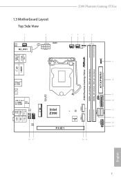
PS2 Keyboard /Mouse USB 3.1 Gen1 T: USB1 B: USB2 1.3 Motherboard Layout Top Side View 1 2 CLR BTN1 CHA_FAN1 M2_WIFI BAT1 RoHS ATX12V1 Z390 Phantom Gaming-ITX/ac 3 4 5 6 CPU_FAN1 1 ADDR_LED1 CPU_OPT/W_PUMP RGB_LED1 7 1 AT X P W R 1 DDR4_B1 (64 bit, 288-pin module) DDR4_A1 (64 bit, 288-pin module) Z390 Phantom Gaming-ITX/ac HDMI1 DP_1 USB 3.1 Gen2 T: USB3 B: USB4 TB_1 Center: REAR SPK Bottom: Optical SPDIF USB 3.1 Gen2...
PS2 Keyboard /Mouse USB 3.1 Gen1 T: USB1 B: USB2 1.3 Motherboard Layout Top Side View 1 2 CLR BTN1 CHA_FAN1 M2_WIFI BAT1 RoHS ATX12V1 Z390 Phantom Gaming-ITX/ac 3 4 5 6 CPU_FAN1 1 ADDR_LED1 CPU_OPT/W_PUMP RGB_LED1 7 1 AT X P W R 1 DDR4_B1 (64 bit, 288-pin module) DDR4_A1 (64 bit, 288-pin module) Z390 Phantom Gaming-ITX/ac HDMI1 DP_1 USB 3.1 Gen2 T: USB3 B: USB4 TB_1 Center: REAR SPK Bottom: Optical SPDIF USB 3.1 Gen2...
User Manual
Page 19
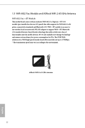
BT 5.0 also includes Low Energy Technology and ensures extraordinary low power consumption for WiFi 802.11 a/b/ g/n/ac connectivity standards and Bluetooth v5.0. The 2T2R WiFi solution sets a WiFi high speed standard and offers max link rate up to 1733Mbps. * ... an easy-touse wireless local area network (WLAN) adapter to the environment. ASRock WiFi 2.4/5 GHz Antenna 12 English 1.5 WiFi-802.11ac Module and ASRock WiFi 2.4/5 GHz Antenna WiFi-802.11ac + BT Module This motherboard comes with an exclusive WiFi 802.11 a/b/g/n/ac + BT v5.0 module (pre-installed on the rear I/O panel) that ...
BT 5.0 also includes Low Energy Technology and ensures extraordinary low power consumption for WiFi 802.11 a/b/ g/n/ac connectivity standards and Bluetooth v5.0. The 2T2R WiFi solution sets a WiFi high speed standard and offers max link rate up to 1733Mbps. * ... an easy-touse wireless local area network (WLAN) adapter to the environment. ASRock WiFi 2.4/5 GHz Antenna 12 English 1.5 WiFi-802.11ac Module and ASRock WiFi 2.4/5 GHz Antenna WiFi-802.11ac + BT Module This motherboard comes with an exclusive WiFi 802.11 a/b/g/n/ac + BT v5.0 module (pre-installed on the rear I/O panel) that ...
User Manual
Page 20
...; In order to avoid damage from static electricity to the motherboard's components, NEVER place your chassis to do not touch the ICs. • Whenever you install motherboard components or change any components, place them on a carpet. Z390 Phantom Gaming-ITX/ac Chapter 2 Installation This is a Mini-ITX form factor motherboard. Failure to ensure that comes with the components. •...
...; In order to avoid damage from static electricity to the motherboard's components, NEVER place your chassis to do not touch the ICs. • Whenever you install motherboard components or change any components, place them on a carpet. Z390 Phantom Gaming-ITX/ac Chapter 2 Installation This is a Mini-ITX form factor motherboard. Failure to ensure that comes with the components. •...
User Manual
Page 23
Please save and replace the cover if the processor is removed. The cover must be placed if you wish to return the motherboard for after service. 16 English
Please save and replace the cover if the processor is removed. The cover must be placed if you wish to return the motherboard for after service. 16 English
User Manual
Page 25
... a DDR4 slot; It is unable to activate Dual Channel Memory Technology with only one correct orientation. It will cause permanent damage to the motherboard and the DIMM if you always need to install a DDR, DDR2 or DDR3 memory module into the slot at incorrect orientation. 18 English... 2.3 Installing Memory Modules (DIMM) This motherboard provides two 288-pin DDR4 (Double Data Rate 4) DIMM slots, and supports Dual Channel Memory Technology. 1. The DIMM only fits in one memory...
... a DDR4 slot; It is unable to activate Dual Channel Memory Technology with only one correct orientation. It will cause permanent damage to the motherboard and the DIMM if you always need to install a DDR, DDR2 or DDR3 memory module into the slot at incorrect orientation. 18 English... 2.3 Installing Memory Modules (DIMM) This motherboard provides two 288-pin DDR4 (Double Data Rate 4) DIMM slots, and supports Dual Channel Memory Technology. 1. The DIMM only fits in one memory...
User Manual
Page 27
2.4 Expansion Slots (PCI Express Slot) There is used for the card before you start the installation. Please read the documentation of the expansion card and make sure that the power supply is switched off or the power cord is unplugged. PCIe slot: PCIE1 (PCIe 3.0 x16 slot) is 1 PCI Express slot slot on the motherboard. Before installing an expansion card, please make necessary hardware settings for PCI Express x16 lane width graphics cards. 20 English
2.4 Expansion Slots (PCI Express Slot) There is used for the card before you start the installation. Please read the documentation of the expansion card and make sure that the power supply is switched off or the power cord is unplugged. PCIe slot: PCIE1 (PCIe 3.0 x16 slot) is 1 PCI Express slot slot on the motherboard. Before installing an expansion card, please make necessary hardware settings for PCI Express x16 lane width graphics cards. 20 English
User Manual
Page 28
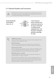
... a normal restart. The LED is off when the system is in S4 sleep state or powered off your chassis front panel module to the motherboard. A front panel module mainly consists of power button, reset button, power LED, hard drive activity LED, speaker and etc. The front panel.... The LED is on when the hard drive is operating. The LED keeps blinking when the system is in S1/S3 sleep state. Z390 Phantom Gaming-ITX/ac 2.5 Onboard Headers and Connectors Onboard headers and connectors are matched correctly. Do NOT place jumper caps over the headers and connectors will cause ...
... a normal restart. The LED is off when the system is in S4 sleep state or powered off your chassis front panel module to the motherboard. A front panel module mainly consists of power button, reset button, power LED, hard drive activity LED, speaker and etc. The front panel.... The LED is on when the hard drive is operating. The LED keeps blinking when the system is in S1/S3 sleep state. Z390 Phantom Gaming-ITX/ac 2.5 Onboard Headers and Connectors Onboard headers and connectors are matched correctly. Do NOT place jumper caps over the headers and connectors will cause ...
User Manual
Page 29
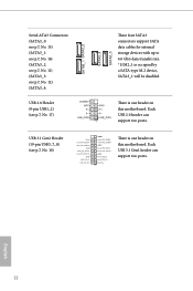
Each USB 2.0 header can support two ports. English 22 Each USB 3.1 Gen1 header can support two ports. There is one header on this motherboard. Serial ATA3 Connectors (SATA3_0: see p.7, No. 15) (SATA3_1: see p.7, No. 16) (SATA3_2: see p.7, No. 11) (SATA3_3: see p.7, No. 12) (SATA3_4: USB 2.0 Header (9-pin USB1_2) (see p.7, ... four SATA3 connectors support SATA data cables for internal storage devices with up to 6.0 Gb/s data transfer rate. * If M2_1 is one header on this motherboard.
Each USB 2.0 header can support two ports. English 22 Each USB 3.1 Gen1 header can support two ports. There is one header on this motherboard. Serial ATA3 Connectors (SATA3_0: see p.7, No. 15) (SATA3_1: see p.7, No. 16) (SATA3_2: see p.7, No. 11) (SATA3_3: see p.7, No. 12) (SATA3_4: USB 2.0 Header (9-pin USB1_2) (see p.7, ... four SATA3 connectors support SATA data cables for internal storage devices with up to 6.0 Gb/s data transfer rate. * If M2_1 is one header on this motherboard.
User Manual
Page 30
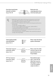
... E. CPU Fan Connector (4-pin CPU_FAN1) (see p.7, No. 1) match the black wire to OUT2_L. English 23 B. Z390 Phantom Gaming-ITX/ac Front Panel Audio Header (9-pin HD_AUDIO1) (see p.7, No. 18) OUT_RET MIC_RET PRESENCE# GN D OUT2_L J_SENSE This header ... Fan Connector FAN_SPEED FAN_VOLTAGE_CONTROL Please connect fan cables GND FAN_SPEED_CONTROL (4-pin CHA_FAN1) to the fan connector and (see p.7, No. 3) FAN_SPEED This motherboard pro- Connect Audio_R (RIN) to OUT2_R and Audio_L (LIN) to the ground pin. To activate the front mic, go to function correctly...
... E. CPU Fan Connector (4-pin CPU_FAN1) (see p.7, No. 1) match the black wire to OUT2_L. English 23 B. Z390 Phantom Gaming-ITX/ac Front Panel Audio Header (9-pin HD_AUDIO1) (see p.7, No. 18) OUT_RET MIC_RET PRESENCE# GN D OUT2_L J_SENSE This header ... Fan Connector FAN_SPEED FAN_VOLTAGE_CONTROL Please connect fan cables GND FAN_SPEED_CONTROL (4-pin CHA_FAN1) to the fan connector and (see p.7, No. 3) FAN_SPEED This motherboard pro- Connect Audio_R (RIN) to OUT2_R and Audio_L (LIN) to the ground pin. To activate the front mic, go to function correctly...
User Manual
Page 31
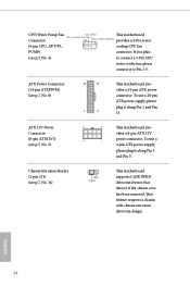
...1 power connector. Chassis Intrusion Header (2-pin CI1) (see p.7, No. 2) 8 5 This motherboard pro- English 24 ATX 12V Power Connector (8-pin ATX12V1) (see p.7, No. 14) 1 GND Signal This motherboard supports CASE OPEN detection feature that detects if the chassis cove has been removed. CPU/Water Pump... Fan FAN_SPEED This motherboard FAN_VOLTAGE_CONTROL Connector GND FAN_SPEED_CONTROL provides a 4-Pin water (4-pin CPU_OPT/W_ cooling CPU fan PUMP) connector. ATX Power Connector ...
...1 power connector. Chassis Intrusion Header (2-pin CI1) (see p.7, No. 2) 8 5 This motherboard pro- English 24 ATX 12V Power Connector (8-pin ATX12V1) (see p.7, No. 14) 1 GND Signal This motherboard supports CASE OPEN detection feature that detects if the chassis cove has been removed. CPU/Water Pump... Fan FAN_SPEED This motherboard FAN_VOLTAGE_CONTROL Connector GND FAN_SPEED_CONTROL provides a 4-Pin water (4-pin CPU_OPT/W_ cooling CPU fan PUMP) connector. ATX Power Connector ...
User Manual
Page 33
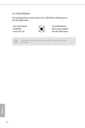
This function is workable only when you power off your computer and unplug the power supply. English 26 Clear CMOS Button (CLRCBTN) (see p.10, No. 16) Clear CMOS Button allows users to clear the CMOS values. 2.6 Smart Button The motherboard has one smart button: Clear CMOS Button, allowing users to quickly clear the CMOS values.
This function is workable only when you power off your computer and unplug the power supply. English 26 Clear CMOS Button (CLRCBTN) (see p.10, No. 16) Clear CMOS Button allows users to clear the CMOS values. 2.6 Smart Button The motherboard has one smart button: Clear CMOS Button, allowing users to quickly clear the CMOS values.
User Manual
Page 34
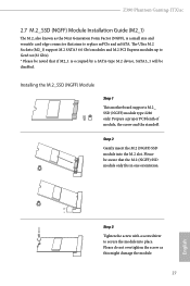
... Gb/s). * Please be disabled. Installing the M.2_SSD (NGFF) Module Step 1 This motherboard supports M.2_ SSD (NGFF) module type 2280 only. Please be aware that if M2_1 is a small size and versatile card edge connector that aims to replace mPCIe and mSATA. Z390 Phantom Gaming-ITX/ac 2.7 M.2_SSD (NGFF) Module Installation Guide (M2_1) The M.2, also known as...
... Gb/s). * Please be disabled. Installing the M.2_SSD (NGFF) Module Step 1 This motherboard supports M.2_ SSD (NGFF) module type 2280 only. Please be aware that if M2_1 is a small size and versatile card edge connector that aims to replace mPCIe and mSATA. Z390 Phantom Gaming-ITX/ac 2.7 M.2_SSD (NGFF) Module Installation Guide (M2_1) The M.2, also known as...


