Intel Smart Response Installation Guide
Page 1
... It is not necessary to desktop, open , click on the "Enable Acceleration" button on the GUI panel. 5. Intel Smart Response Technology Installation Guide This motherboard supports Intel Smart Response Technology. UI setup instruction: 1. Once open RST GUI from either Start Menu or by step instructions below. You can find the...both the HDD you intend to [RAID Mode]. For the new version RST driver, please check our website for the latest information: http://www.asrock.com * Before you just need to set the UEFI option "SATA Mode" to accelerate AND the SSD in Icon tray, lower right-hand ...
... It is not necessary to desktop, open , click on the "Enable Acceleration" button on the GUI panel. 5. Intel Smart Response Technology Installation Guide This motherboard supports Intel Smart Response Technology. UI setup instruction: 1. Once open RST GUI from either Start Menu or by step instructions below. You can find the...both the HDD you intend to [RAID Mode]. For the new version RST driver, please check our website for the latest information: http://www.asrock.com * Before you just need to set the UEFI option "SATA Mode" to accelerate AND the SSD in Icon tray, lower right-hand ...

Intel Rapid Storage Guide
Page 12
... system onto a RAID volume, the RAID option must be enabled in the system BIOS. 1. Enable RAID in System BIOS Use the instructions included with your motherboard to enter the BIOS Setup program after the Power-On-Self-Test (POST) memory test begins. 2.
... system onto a RAID volume, the RAID option must be enabled in the system BIOS. 1. Enable RAID in System BIOS Use the instructions included with your motherboard to enter the BIOS Setup program after the Power-On-Self-Test (POST) memory test begins. 2.

RAID Installation Guide
Page 2
Guide to the Intel southbridge chipset that your motherboard adopts. You may install SATA hard disks on SATA ports. 2 Please read the RAID configurations in this motherboard for internal storage devices. 1. This section will guide you how to create RAID on this guide carefully according to SATA Hard Disks Installation 1.1 Serial ATA (SATA) Hard Disks Installation Intel chipset supports Serial ATA (SATA) hard disks with RAID functions, including RAID 0, RAID 1, RAID 5, RAID 10 and Intel Rapid Storage.
Guide to the Intel southbridge chipset that your motherboard adopts. You may install SATA hard disks on SATA ports. 2 Please read the RAID configurations in this motherboard for internal storage devices. 1. This section will guide you how to create RAID on this guide carefully according to SATA Hard Disks Installation 1.1 Serial ATA (SATA) Hard Disks Installation Intel chipset supports Serial ATA (SATA) hard disks with RAID functions, including RAID 0, RAID 1, RAID 5, RAID 10 and Intel Rapid Storage.

RAID Installation Guide
Page 3
... at a sustained data transfer rate. 2. This section will cause data damage or data loss. RAID The term "RAID" stands for "Redundant Array of RAID This motherboard adopts Intel southbridge chipset that optimizes two identical hard disk drives to read and write data in the other drive if one drive to RAID...
... at a sustained data transfer rate. 2. This section will cause data damage or data loss. RAID The term "RAID" stands for "Redundant Array of RAID This motherboard adopts Intel southbridge chipset that optimizes two identical hard disk drives to read and write data in the other drive if one drive to RAID...

RAID Installation Guide
Page 23
... 64-bit. 4. STEP 1: Copy Intel® RAID drivers into a USB flash disk You can download the drivers from ASRock's website and unzip the files into a USB flash disk or copy the files from ASRock's motherboard support CD. (Please copy the files under the following directory: 32 bit: ..\i386\Win7_Intel.. 64-bit: ..\AMD64\Win7...
... 64-bit. 4. STEP 1: Copy Intel® RAID drivers into a USB flash disk You can download the drivers from ASRock's website and unzip the files into a USB flash disk or copy the files from ASRock's motherboard support CD. (Please copy the files under the following directory: 32 bit: ..\i386\Win7_Intel.. 64-bit: ..\AMD64\Win7...

RAID Installation Guide
Page 25
... 64-bit, install the hotfix kb2505454. (This may take more time to fix this problem. Disk volume > 2TB), it may take about 5 minutes to install motherboard drivers and utilities. 25
... 64-bit, install the hotfix kb2505454. (This may take more time to fix this problem. Disk volume > 2TB), it may take about 5 minutes to install motherboard drivers and utilities. 25

User Manual
Page 2
.... Copyright Notice: No part of this documentation may not be liable for any form or by ASRock. This device complies with Part 15 of this motherboard contains Perchlorate, a toxic substance controlled in this documentation may or may be constructed as a commitment by any errors or omissions that may apply, see www....
.... Copyright Notice: No part of this documentation may not be liable for any form or by ASRock. This device complies with Part 15 of this motherboard contains Perchlorate, a toxic substance controlled in this documentation may or may be constructed as a commitment by any errors or omissions that may apply, see www....

User Manual
Page 4
Contents Chapter 1 Introduction 1 1.1 Package Contents 1 1.2 Specifications 2 1.3 Motherboard Layout 8 1.4 I/O Panel 10 1.5 WiFi-802.11ac Module and ASRock WiFi 2.4/5 GHz Antenna 12 Chapter 2 Installation 14 2.1 Installing the CPU 15 2.2 Installing the CPU Fan and Heatsink 18 2.3 Installing Memory Modules (DIMM) 19 2.4 Expansion Slots (...
Contents Chapter 1 Introduction 1 1.1 Package Contents 1 1.2 Specifications 2 1.3 Motherboard Layout 8 1.4 I/O Panel 10 1.5 WiFi-802.11ac Module and ASRock WiFi 2.4/5 GHz Antenna 12 Chapter 2 Installation 14 2.1 Installing the CPU 15 2.2 Installing the CPU Fan and Heatsink 18 2.3 Installing Memory Modules (DIMM) 19 2.4 Expansion Slots (...
User Manual
Page 8
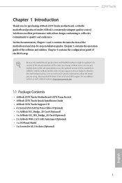
... further notice. ASRock website http://www.asrock.com. 1.1 Package Contents • ASRock Z270 Taichi Motherboard (ATX Form Factor) • ASRock Z270 Taichi Quick Installation Guide • ASRock Z270 Taichi Support CD • 4 x Serial ATA (SATA) Data Cables (Optional) • 1 x ASRock SLI_Bridge_2S Card (Optional) • 1 x ASRock SLI_HB_Bridge_2S Card (Optional) • 2 x ASRock WiFi 2.4/5 GHz Antennas (Optional) • 1 x I/O Panel Shield • 3 x Screws for purchasing ASRock Z270 Taichi motherboard, a reliable motherboard produced under ASRock's consistently...
... further notice. ASRock website http://www.asrock.com. 1.1 Package Contents • ASRock Z270 Taichi Motherboard (ATX Form Factor) • ASRock Z270 Taichi Quick Installation Guide • ASRock Z270 Taichi Support CD • 4 x Serial ATA (SATA) Data Cables (Optional) • 1 x ASRock SLI_Bridge_2S Card (Optional) • 1 x ASRock SLI_HB_Bridge_2S Card (Optional) • 2 x ASRock WiFi 2.4/5 GHz Antennas (Optional) • 1 x I/O Panel Shield • 3 x Screws for purchasing ASRock Z270 Taichi motherboard, a reliable motherboard produced under ASRock's consistently...

User Manual
Page 15
1.3 Motherboard Layout 1 23 CLRBTN1 ATX12V1 PS2 Keyboard /Mouse USB 3.0 T: USB1 B: USB2 CPU_OPT/W_PUMP M2_WIFI_1 RoHS 4 56 CPU_FAN1 ON 7 OFF XMP_ON1 Intel Optan TMe Ready ® DDR4_A1 (... Bottom: Optical SPDIF Top: Center: FRONT Bottom: MIC IN LAN Ultra M.2 PCIe Gen3 x4 CHA_FAN2 M2_3 CHA_FAN1 CT24 CT23 CT22 CT21 PCIE1 PCIE2 Z270 Taichi CMOS Battery PCIE3 PCIE4 Intel Z270 SATA_EXP0_1 USB3_6_7 USB3_8_9 USB3_10 Vertical Type A USB 3.0 ATXPWR1 1 1 M2_1 SATA3_A3_A4 SATA3_A1_A2 SATA3_4_5 M2_2 HD_AUDIO1 1 27 CT34 CT33 CT32 CT31 CLRMOS1 1 PCIE5 TPMS1...
1.3 Motherboard Layout 1 23 CLRBTN1 ATX12V1 PS2 Keyboard /Mouse USB 3.0 T: USB1 B: USB2 CPU_OPT/W_PUMP M2_WIFI_1 RoHS 4 56 CPU_FAN1 ON 7 OFF XMP_ON1 Intel Optan TMe Ready ® DDR4_A1 (... Bottom: Optical SPDIF Top: Center: FRONT Bottom: MIC IN LAN Ultra M.2 PCIe Gen3 x4 CHA_FAN2 M2_3 CHA_FAN1 CT24 CT23 CT22 CT21 PCIE1 PCIE2 Z270 Taichi CMOS Battery PCIE3 PCIE4 Intel Z270 SATA_EXP0_1 USB3_6_7 USB3_8_9 USB3_10 Vertical Type A USB 3.0 ATXPWR1 1 1 M2_1 SATA3_A3_A4 SATA3_A1_A2 SATA3_4_5 M2_2 HD_AUDIO1 1 27 CT34 CT33 CT32 CT31 CLRMOS1 1 PCIE5 TPMS1...

User Manual
Page 19
... and ensures extraordinary low power consumption for WiFi 802.11 a/b/ g/n/ac connectivity standards and Bluetooth v4.0. 1.5 WiFi-802.11ac Module and ASRock WiFi 2.4/5 GHz Antenna WiFi-802.11ac + BT Module This motherboard comes with an exclusive WiFi 802.11 a/b/g/n/ac + BT v4.0 module (pre-installed on the rear I/O panel) that adds a whole...
... and ensures extraordinary low power consumption for WiFi 802.11 a/b/ g/n/ac connectivity standards and Bluetooth v4.0. 1.5 WiFi-802.11ac Module and ASRock WiFi 2.4/5 GHz Antenna WiFi-802.11ac + BT Module This motherboard comes with an exclusive WiFi 802.11 a/b/g/n/ac + BT v4.0 module (pre-installed on the rear I/O panel) that adds a whole...

User Manual
Page 21
... 2 Installation This is an ATX form factor motherboard. Pre-installation Precautions Take note of your motherboard directly on a grounded anti-static pad or in the bag that the motherboard fits into it. Failure to do so may damage the motherboard. 14 English Doing so may cause physical injuries...your chassis to ensure that comes with the components. • When placing screws to secure the motherboard to the chassis, please do not touch the ICs. • Whenever you uninstall any motherboard settings. • Make sure to use a grounded wrist strap or touch a safety grounded object...
... 2 Installation This is an ATX form factor motherboard. Pre-installation Precautions Take note of your motherboard directly on a grounded anti-static pad or in the bag that the motherboard fits into it. Failure to do so may damage the motherboard. 14 English Doing so may cause physical injuries...your chassis to ensure that comes with the components. • When placing screws to secure the motherboard to the chassis, please do not touch the ICs. • Whenever you uninstall any motherboard settings. • Make sure to use a grounded wrist strap or touch a safety grounded object...

User Manual
Page 24
The cover must be placed if you wish to return the motherboard for after service. 17 English Z270 Taichi Please save and replace the cover if the processor is removed.
The cover must be placed if you wish to return the motherboard for after service. 17 English Z270 Taichi Please save and replace the cover if the processor is removed.

User Manual
Page 26
For dual channel configuration, you force the DIMM into a DDR4 slot; otherwise, this motherboard and DIMM may be damaged. It will cause permanent damage to the motherboard and the DIMM if you always need to install identical (the same brand, speed, size and chip-type) DDR4 DIMM pairs... slot at incorrect orientation. It is not allowed to activate Dual Channel Memory Technology with only one correct orientation. Z270 Taichi 2.3 Installing Memory Modules (DIMM) This motherboard provides four 288-pin DDR4 (Double Data Rate 4) DIMM slots, and supports Dual Channel Memory Technology. 1.
For dual channel configuration, you force the DIMM into a DDR4 slot; otherwise, this motherboard and DIMM may be damaged. It will cause permanent damage to the motherboard and the DIMM if you always need to install identical (the same brand, speed, size and chip-type) DDR4 DIMM pairs... slot at incorrect orientation. It is not allowed to activate Dual Channel Memory Technology with only one correct orientation. Z270 Taichi 2.3 Installing Memory Modules (DIMM) This motherboard provides four 288-pin DDR4 (Double Data Rate 4) DIMM slots, and supports Dual Channel Memory Technology. 1.

User Manual
Page 28
Z270 Taichi 2.4 Expansion Slots (PCI and PCI Express Slots) There are 5 PCI Express slots on the motherboard. PCIE2 (PCIe 3.0 x16 slot) is used for PCI Express x4 lane width graphics cards. PCIE3 (PCIe 3.0 x16 slot) is used for PCI Express x4...or SLITM x8 Mode x8 N/A Three Graphics Cards in 3-Way CrossFireXTM Mode x8 x4 x4 For a better thermal environment, please connect a chassis fan to the motherboard's chassis fan connector (CHA_FAN1, CHA_FAN2 or CHA_FAN3) when using multiple graphics cards. English 21 PCIe slots: PCIE1 (PCIe 3.0 x1 slot) is unplugged. Before ...
Z270 Taichi 2.4 Expansion Slots (PCI and PCI Express Slots) There are 5 PCI Express slots on the motherboard. PCIE2 (PCIe 3.0 x16 slot) is used for PCI Express x4 lane width graphics cards. PCIE3 (PCIe 3.0 x16 slot) is used for PCI Express x4...or SLITM x8 Mode x8 N/A Three Graphics Cards in 3-Way CrossFireXTM Mode x8 x4 x4 For a better thermal environment, please connect a chassis fan to the motherboard's chassis fan connector (CHA_FAN1, CHA_FAN2 or CHA_FAN3) when using multiple graphics cards. English 21 PCIe slots: PCIE1 (PCIe 3.0 x1 slot) is unplugged. Before ...

User Manual
Page 30
... the chassis front panel. The front panel design may configure the way to turn off (S5). Z270 Taichi 2.6 Onboard Headers and Connectors Onboard headers and connectors are matched correctly. RESET (Reset Switch): Connect to the motherboard. The LED is off when the system is in S4 sleep state or powered off your chassis...
... the chassis front panel. The front panel design may configure the way to turn off (S5). Z270 Taichi 2.6 Onboard Headers and Connectors Onboard headers and connectors are matched correctly. RESET (Reset Switch): Connect to the motherboard. The LED is off when the system is in S4 sleep state or powered off your chassis...

User Manual
Page 32
... it to the "FrontMic" Tab in our manual and chassis manual to Ground (GND). C. MIC_RET and OUT_RET are three USB 2.0 headers on this motherboard. You don't need to MIC2_L. Each USB 3.0 header can support two ports. Front Panel Audio Header (9-pin HD_AUDIO1) (see p.8, No. 9)... audio panel only. Connect Mic_IN (MIC) to connect them for the AC'97 audio panel. Connect Audio_R (RIN) to OUT2_R and Audio_L (LIN) to OUT2_L. E. Z270 Taichi USB 2.0 Headers (9-pin USB_11_12) (see p.8, No. 23) (9-pin USB_13_14) (see p.8, No. 22) (9-pin USB_15_16) (see p.8, No. 21) USB 3.0 Headers ...
... it to the "FrontMic" Tab in our manual and chassis manual to Ground (GND). C. MIC_RET and OUT_RET are three USB 2.0 headers on this motherboard. You don't need to MIC2_L. Each USB 3.0 header can support two ports. Front Panel Audio Header (9-pin HD_AUDIO1) (see p.8, No. 9)... audio panel only. Connect Mic_IN (MIC) to connect them for the AC'97 audio panel. Connect Audio_R (RIN) to OUT2_R and Audio_L (LIN) to OUT2_L. E. Z270 Taichi USB 2.0 Headers (9-pin USB_11_12) (see p.8, No. 23) (9-pin USB_13_14) (see p.8, No. 22) (9-pin USB_15_16) (see p.8, No. 21) USB 3.0 Headers ...

User Manual
Page 33
... a 4-Pin CPU fan (Quiet Fan) connector. CPU Fan Connector (4-pin CPU_FAN1) (see p.8, No. 2) FAN_SPEED_CONTROL CPU_FAN_SPEED FAN_VOLTAGE GND This motherboard 4 3 provides a 4-Pin water 2 cooling CPU fan 1 connector. ATX Power Connector (24-pin ATXPWR1) (see p.8, No. 17) 1 234 FAN_SPEED_CONTROL CHA_FAN_SPEED FAN_VOLTAGE ... Pin 1 and Pin 13. English 26 Chassis Fan / Waterpump Fan Connector (4-pin CHA_FAN3/W_ PUMP) (see p.8, No. 8) 12 24 1 13 This motherboard provides a 24-pin ATX power connector. To use a 20-pin ATX power supply, please plug it to the ground pin.
... a 4-Pin CPU fan (Quiet Fan) connector. CPU Fan Connector (4-pin CPU_FAN1) (see p.8, No. 2) FAN_SPEED_CONTROL CPU_FAN_SPEED FAN_VOLTAGE GND This motherboard 4 3 provides a 4-Pin water 2 cooling CPU fan 1 connector. ATX Power Connector (24-pin ATXPWR1) (see p.8, No. 17) 1 234 FAN_SPEED_CONTROL CHA_FAN_SPEED FAN_VOLTAGE ... Pin 1 and Pin 13. English 26 Chassis Fan / Waterpump Fan Connector (4-pin CHA_FAN3/W_ PUMP) (see p.8, No. 8) 12 24 1 13 This motherboard provides a 24-pin ATX power connector. To use a 20-pin ATX power supply, please plug it to the ground pin.

User Manual
Page 34
Z270 Taichi ATX 12V Power Connector (8-pin ATX12V1) (see p.8, No. 1) TPM Header (17-pin TPMS1) (see p.8, No. 25) Thunderbolt AIC Connector (5-pin TB1) (see p.8, No. 24) AURA RGB LED Header (4-pin RGB_LED1) (see p.8, No. 20) GND SERIRQ # S_PWRDWN # GN D LAD1 LAD2 SMB_DATA_MAIN SMB_CLK_MAIN GN D +3VS B LAD0 +3V LAD3 PCIRST # FRAM E PCICLK 8 5 This motherboard pro...
Z270 Taichi ATX 12V Power Connector (8-pin ATX12V1) (see p.8, No. 1) TPM Header (17-pin TPMS1) (see p.8, No. 25) Thunderbolt AIC Connector (5-pin TB1) (see p.8, No. 24) AURA RGB LED Header (4-pin RGB_LED1) (see p.8, No. 20) GND SERIRQ # S_PWRDWN # GN D LAD1 LAD2 SMB_DATA_MAIN SMB_CLK_MAIN GN D +3VS B LAD0 +3V LAD3 PCIRST # FRAM E PCICLK 8 5 This motherboard pro...

User Manual
Page 35
... the CMOS values. This function is workable only when you power off the system, reset the system or clear the CMOS values. 2.7 Smart Switches The motherboard has three smart switches: Power Switch, Reset Switch and Clear CMOS Switch, allowing users to quickly turn on/off your computer and unplug the power...
... the CMOS values. This function is workable only when you power off the system, reset the system or clear the CMOS values. 2.7 Smart Switches The motherboard has three smart switches: Power Switch, Reset Switch and Clear CMOS Switch, allowing users to quickly turn on/off your computer and unplug the power...


