User Manual
Page 7
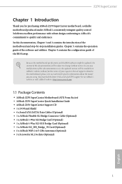
... of the motherboard and step-by-step installation guides. Z270 SuperCarrier Chapter 1 Introduction Thank you for M.2 Sockets (Optional) 1 English Chapter 4 contains the configuration guide of the software and utilities. ASRock website http://www.asrock.com. 1.1 Package Contents • ASRock Z270 SuperCarrier Motherboard (ATX Form Factor) • ASRock Z270 SuperCarrier Quick Installation Guide • ASRock Z270 SuperCarrier Support CD • 1 x I/O Panel Shield • 4 x Serial ATA...
... of the motherboard and step-by-step installation guides. Z270 SuperCarrier Chapter 1 Introduction Thank you for M.2 Sockets (Optional) 1 English Chapter 4 contains the configuration guide of the software and utilities. ASRock website http://www.asrock.com. 1.1 Package Contents • ASRock Z270 SuperCarrier Motherboard (ATX Form Factor) • ASRock Z270 SuperCarrier Quick Installation Guide • ASRock Z270 SuperCarrier Support CD • 1 x I/O Panel Shield • 4 x Serial ATA...

User Manual
Page 8
... (PCIE1) / x8 (PCIE2) / x16 (PCIE4); triple at x16 (PCIE1) / x16 (PCIE4); 1.2 Specifications Platform CPU • ATX Form Factor • 2oz Copper • Supports 7th and 6th Generation Intel® CoreTM i7/i5/i3/ Pentium®/Celeron® Processors...Supports Intel® Turbo Boost 2.0 Technology • Supports Intel® K-Series unlocked CPUs • Supports ASRock BCLK Full-range Overclocking • Supports ASRock Hyper BCLK Engine II Chipset • Intel® Z270 Memory • Dual Channel DDR4 Memory Technology • 4 x DDR4 DIMM Slots • Supports DDR4 ...
... (PCIE1) / x8 (PCIE2) / x16 (PCIE4); triple at x16 (PCIE1) / x16 (PCIE4); 1.2 Specifications Platform CPU • ATX Form Factor • 2oz Copper • Supports 7th and 6th Generation Intel® CoreTM i7/i5/i3/ Pentium®/Celeron® Processors...Supports Intel® Turbo Boost 2.0 Technology • Supports Intel® K-Series unlocked CPUs • Supports ASRock BCLK Full-range Overclocking • Supports ASRock Hyper BCLK Engine II Chipset • Intel® Z270 Memory • Dual Channel DDR4 Memory Technology • 4 x DDR4 DIMM Slots • Supports DDR4 ...

User Manual
Page 12
... Front Panel Audio Connector* * Connect the audio device to either one of maximum 1.5A (18W) fan power. • 1 x 24 pin ATX Power Connector (Hi-Density Power Con- nector) • 1 x 8 pin 12V Power Connector (Hi-Density Power Connec- tor) • 1... 2.0 Headers (Support 4 USB 2.0 ports) (Intel® Z270) (Supports ESD Protection (ASRock Full Spike Protection)) • 2 x USB 3.0 Headers (Support 4 USB 3.0 ports) (ASMedia ASM1074 hub) (Supports ESD Protection (ASRock Full Spike Protection)) • 1 x Vertical Type A USB 3.0 (Intel® Z270) • 1 x Dr. Debug with LED • ...
... Front Panel Audio Connector* * Connect the audio device to either one of maximum 1.5A (18W) fan power. • 1 x 24 pin ATX Power Connector (Hi-Density Power Con- nector) • 1 x 8 pin 12V Power Connector (Hi-Density Power Connec- tor) • 1... 2.0 Headers (Support 4 USB 2.0 ports) (Intel® Z270) (Supports ESD Protection (ASRock Full Spike Protection)) • 2 x USB 3.0 Headers (Support 4 USB 3.0 ports) (ASMedia ASM1074 hub) (Supports ESD Protection (ASRock Full Spike Protection)) • 1 x Vertical Type A USB 3.0 (Intel® Z270) • 1 x Dr. Debug with LED • ...
User Manual
Page 15
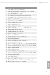
Z270 SuperCarrier No. Description 1 ATX 12V Power Connector (ATX12V1) 2 CPU Fan / Waterpump Fan Connector (CPU_OPT/W_PUMP) 3 CPU Fan Connector (CPU_FAN1) 4 2 x 288-pin DDR4 DIMM Slots (DDR4_A1, DDR4_B1) 5 2 x 288-pin DDR4 DIMM Slots (DDR4_A2, DDR4_B2) 6 XMP Switch (XMP_ON1) 7 ATX Power Connector (ATXPWR1) 8 Vertical Type A USB 3.0 (USB3_9) 9 USB 3.0 Header (USB3_7_8) 10 USB 3.0 Header (USB3_5_6) 11 SATA and...
Z270 SuperCarrier No. Description 1 ATX 12V Power Connector (ATX12V1) 2 CPU Fan / Waterpump Fan Connector (CPU_OPT/W_PUMP) 3 CPU Fan Connector (CPU_FAN1) 4 2 x 288-pin DDR4 DIMM Slots (DDR4_A1, DDR4_B1) 5 2 x 288-pin DDR4 DIMM Slots (DDR4_A2, DDR4_B2) 6 XMP Switch (XMP_ON1) 7 ATX Power Connector (ATXPWR1) 8 Vertical Type A USB 3.0 (USB3_9) 9 USB 3.0 Header (USB3_7_8) 10 USB 3.0 Header (USB3_5_6) 11 SATA and...
User Manual
Page 21
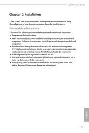
Pre-installation Precautions Take note of the following precautions before you install motherboard components or change any components, place them on a carpet. Z270 SuperCarrier Chapter 2 Installation This is an ATX form factor motherboard. Failure to unplug the power cord before you handle the components. • Hold components by the edges and do not touch...
Pre-installation Precautions Take note of the following precautions before you install motherboard components or change any components, place them on a carpet. Z270 SuperCarrier Chapter 2 Installation This is an ATX form factor motherboard. Failure to unplug the power cord before you handle the components. • Hold components by the edges and do not touch...

User Manual
Page 33
...CPU Optional/Water Pump Fan Connector (4-pin CPU_OPT/W_ PUMP) (see p.8, No. 7) 12 24 1 13 This motherboard provides a 24-pin ATX power connector. Z270 SuperCarrier Chassis Optional/Water This motherboard Pump Fan Connector provides two 4-Pin water (4-pin CHA_FAN1/W_ cooling chassis fan PUMP) (see p.8, No. 3) GND... 4-Pin CPU fan (Quiet Fan) connector. If you plan to connect a 3-Pin CPU fan, please connect it to Pin 1-3. To use a 20-pin ATX power supply, please plug it to Pin 1-3. (see p.8, No. 21) (4-pin CHA_FAN3/W_ PUMP) (see p.8, No. 20) CPU Fan Connector (4-pin CPU_FAN1...
...CPU Optional/Water Pump Fan Connector (4-pin CPU_OPT/W_ PUMP) (see p.8, No. 7) 12 24 1 13 This motherboard provides a 24-pin ATX power connector. Z270 SuperCarrier Chassis Optional/Water This motherboard Pump Fan Connector provides two 4-Pin water (4-pin CHA_FAN1/W_ cooling chassis fan PUMP) (see p.8, No. 3) GND... 4-Pin CPU fan (Quiet Fan) connector. If you plan to connect a 3-Pin CPU fan, please connect it to Pin 1-3. To use a 20-pin ATX power supply, please plug it to Pin 1-3. (see p.8, No. 21) (4-pin CHA_FAN3/W_ PUMP) (see p.8, No. 20) CPU Fan Connector (4-pin CPU_FAN1...

User Manual
Page 34
...) (see p.8, No. 27) AURA RGB LED Header (4-pin RGB_LED) (see p.8, No. 26) 8 5 4 1 4 1 6 3 This motherboard provides a 8-pin ATX 12V power connector. A TPM system also helps enhance network security, protects digital identities, and ensures platform integrity. 1 12V G R B AURA RGB LED header is used to...supports a serial port module. Caution: Never install the RGB LED cable in the wrong orientation; To use a 4-pin ATX power supply, please plug it along Pin 1 and Pin 5. ATX 12V Power Connector (8-pin ATX12V1) (see p.8, No. 1) Graphics 12V Power Connector (6-pin GFX_12V1) (see p.8, No. ...
...) (see p.8, No. 27) AURA RGB LED Header (4-pin RGB_LED) (see p.8, No. 26) 8 5 4 1 4 1 6 3 This motherboard provides a 8-pin ATX 12V power connector. A TPM system also helps enhance network security, protects digital identities, and ensures platform integrity. 1 12V G R B AURA RGB LED header is used to...supports a serial port module. Caution: Never install the RGB LED cable in the wrong orientation; To use a 4-pin ATX power supply, please plug it along Pin 1 and Pin 5. ATX 12V Power Connector (8-pin ATX12V1) (see p.8, No. 1) Graphics 12V Power Connector (6-pin GFX_12V1) (see p.8, No. ...
