
User Manual
Page 4
... Specifications 2 1.3 Motherboard Layout 8 1.4 I/O Panel 10 1.5 WiFi-802.11ac Module and ASRock WiFi 2.4/5 GHz Antenna 13 Chapter 2 Installation 15 2.1 Installing the CPU 16 2.2 Installing the CPU Fan and Heatsink 19 2.3 Installing Memory Modules (DIMM) 20 2.4 Expansion Slots (PCI Express Slots) 22 2.5 Jumpers Setup 23 2.6 Onboard Headers and Connectors 24 2.7 Smart Switches 29 2.8 Dr. Debug 30 2.9 SLITM , 3-Way SLITM , 4-Way SLITM and Quad SLITM Operation Guide 32 2.9.1 Installing Two SLITM-Ready Graphics Cards 32 2.9.2 Installing Three SLITM-Ready Graphics Cards...
... Specifications 2 1.3 Motherboard Layout 8 1.4 I/O Panel 10 1.5 WiFi-802.11ac Module and ASRock WiFi 2.4/5 GHz Antenna 13 Chapter 2 Installation 15 2.1 Installing the CPU 16 2.2 Installing the CPU Fan and Heatsink 19 2.3 Installing Memory Modules (DIMM) 20 2.4 Expansion Slots (PCI Express Slots) 22 2.5 Jumpers Setup 23 2.6 Onboard Headers and Connectors 24 2.7 Smart Switches 29 2.8 Dr. Debug 30 2.9 SLITM , 3-Way SLITM , 4-Way SLITM and Quad SLITM Operation Guide 32 2.9.1 Installing Two SLITM-Ready Graphics Cards 32 2.9.2 Installing Three SLITM-Ready Graphics Cards...

User Manual
Page 5
...-Ready Graphics Cards 41 2.10.4 Driver Installation and Setup 42 2.11 M.2_SSD (NGFF) Module Installation Guide 43 Chapter 3 Software and Utilities Operation 46 3.1 Installing Drivers 46 3.2 A-Tuning 47 3.3 ASRock Live Update & APP Shop 50 3.3.1 UI Overview 50 3.3.2 Apps 51 3.3.3 BIOS & Drivers 54 3.3.4 Setting 55 3.4 Enabling USB Ports for Windows® 7 Installation 56 3.5 ASRock AURA RGB LED 59 Chapter 4 UEFI SETUP UTILITY 60 4.1 Introduction 60 4.2 EZ Mode 61 4.3 Advanced Mode 62 4.3.1 UEFI Menu Bar 62 4.3.2 Navigation Keys 63 4.4 Main Screen 64...
...-Ready Graphics Cards 41 2.10.4 Driver Installation and Setup 42 2.11 M.2_SSD (NGFF) Module Installation Guide 43 Chapter 3 Software and Utilities Operation 46 3.1 Installing Drivers 46 3.2 A-Tuning 47 3.3 ASRock Live Update & APP Shop 50 3.3.1 UI Overview 50 3.3.2 Apps 51 3.3.3 BIOS & Drivers 54 3.3.4 Setting 55 3.4 Enabling USB Ports for Windows® 7 Installation 56 3.5 ASRock AURA RGB LED 59 Chapter 4 UEFI SETUP UTILITY 60 4.1 Introduction 60 4.2 EZ Mode 61 4.3 Advanced Mode 62 4.3.1 UEFI Menu Bar 62 4.3.2 Navigation Keys 63 4.4 Main Screen 64...
User Manual
Page 7
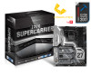
... to change without further notice. Because the motherboard specifications and the BIOS software might be subject to quality and endurance. You may find the latest VGA cards and CPU support list on ASRock's website without notice. ASRock website http://www.asrock.com. 1.1 Package Contents • ASRock Z270 SuperCarrier Motherboard (ATX Form Factor) • ASRock Z270 SuperCarrier Quick Installation Guide • ASRock Z270 SuperCarrier Support CD • 1 x I/O Panel Shield • 4 x Serial ATA (SATA) Data Cables (Optional) • 1 x ASRock Flexible SLI Bridge Connector Cable...
... to change without further notice. Because the motherboard specifications and the BIOS software might be subject to quality and endurance. You may find the latest VGA cards and CPU support list on ASRock's website without notice. ASRock website http://www.asrock.com. 1.1 Package Contents • ASRock Z270 SuperCarrier Motherboard (ATX Form Factor) • ASRock Z270 SuperCarrier Quick Installation Guide • ASRock Z270 SuperCarrier Support CD • 1 x I/O Panel Shield • 4 x Serial ATA (SATA) Data Cables (Optional) • 1 x ASRock Flexible SLI Bridge Connector Cable...

User Manual
Page 9
... HBR (High Bit Rate Audio) with HDMI Port (Compliant HDMI monitor is required) • Supports HDCP with HDMI, DisplayPort 1.2 and Intel® ThunderboltTM 3 • Supports Full HD 1080p Blu-ray (BD) playback with max. shared memory 1024MB * The size of maximum shared memory may vary from different operating systems. • Four graphics output options: HDMI, DisplayPort 1.2 and 2 x Intel® ThunderboltTM 3 • Supports Triple Monitor * Supports up to 3 displays simultaneously • Supports HDMI with max.
... HBR (High Bit Rate Audio) with HDMI Port (Compliant HDMI monitor is required) • Supports HDCP with HDMI, DisplayPort 1.2 and Intel® ThunderboltTM 3 • Supports Full HD 1080p Blu-ray (BD) playback with max. shared memory 1024MB * The size of maximum shared memory may vary from different operating systems. • Four graphics output options: HDMI, DisplayPort 1.2 and 2 x Intel® ThunderboltTM 3 • Supports Triple Monitor * Supports up to 3 displays simultaneously • Supports HDMI with max.
User Manual
Page 11
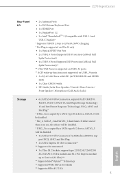
...)) • 4 x USB 3.0 Ports (Supports ESD Protection (ASRock Full Spike Protection))** ** Ultra USB Power is supported on USB3_34 ports. ** ACPI wake-up function is not supported on USB3_34 ports. • 3 x RJ-45 LAN Ports with LED (ACT/LINK LED and SPEED LED) • 1 x Clear CMOS Switch • HD Audio Jacks: Rear Speaker / Central / Bass / Line in use, the others will be disabled. * If M2_3 is occupied by a SATA-type M.2 device, SATA3_0 will be disabled. • 4 x SATA3 6.0 Gb/s Connectors by a SATA-type M.2 device, SATA3_3 will...
...)) • 4 x USB 3.0 Ports (Supports ESD Protection (ASRock Full Spike Protection))** ** Ultra USB Power is supported on USB3_34 ports. ** ACPI wake-up function is not supported on USB3_34 ports. • 3 x RJ-45 LAN Ports with LED (ACT/LINK LED and SPEED LED) • 1 x Clear CMOS Switch • HD Audio Jacks: Rear Speaker / Central / Bass / Line in use, the others will be disabled. * If M2_3 is occupied by a SATA-type M.2 device, SATA3_0 will be disabled. • 4 x SATA3 6.0 Gb/s Connectors by a SATA-type M.2 device, SATA3_3 will...

User Manual
Page 13
... instructions. * For the updated Windows® 10 driver, please visit ASRock's website for possible damage caused by CPU temperature): CPU, CPU Optional/Water Pump, Chassis Optional/ Water Pump Fans • Fan Multi-Speed Control: CPU, CPU Optional/Water Pump, Chassis Optional/Water Pump Fans • Voltage monitoring: +12V, +5V, +3.3V, CPU Vcore, DRAM, VPPM, PCH 1.0V, VCCSA, VCCST • Microsoft® Windows® 10 64-bit (For 7th Gen Intel® CPU) • Microsoft® Windows® 10 64-bit / 8.1 64-bit...
... instructions. * For the updated Windows® 10 driver, please visit ASRock's website for possible damage caused by CPU temperature): CPU, CPU Optional/Water Pump, Chassis Optional/ Water Pump Fans • Fan Multi-Speed Control: CPU, CPU Optional/Water Pump, Chassis Optional/Water Pump Fans • Voltage monitoring: +12V, +5V, +3.3V, CPU Vcore, DRAM, VPPM, PCH 1.0V, VCCSA, VCCST • Microsoft® Windows® 10 64-bit (For 7th Gen Intel® CPU) • Microsoft® Windows® 10 64-bit / 8.1 64-bit...
User Manual
Page 15
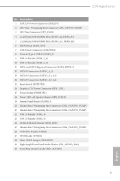
...288-pin DDR4 DIMM Slots (DDR4_A2, DDR4_B2) 6 XMP Switch (XMP_ON1) 7 ATX Power Connector (ATXPWR1) 8 Vertical Type A USB 3.0 (USB3_9) 9 USB 3.0 Header (USB3_7_8) 10 USB 3.0 Header (USB3_5_6) 11 SATA and SATA Express Connectors (SATA_EXP0_1) 12 SATA3 Connectors (SATA3_4_5) 13 SATA3 Connectors (SATA3_A1_A2) 14 SATA3 Connectors (SATA3_A3_A4) 15 Reset Switch (RSTBTN1) 16 Graphics 12V Power Connector (GFX_12V1) 17 Power Switch (PWRBTN1) 18 Power LED and Speaker Header (SPK_PLED1) 19 System Panel Header (PANEL1) 20 Chassis Fan / Waterpump Fan Connector (CHA_FAN3/W_PUMP) 21 Chassis Fan / Waterpump Fan...
...288-pin DDR4 DIMM Slots (DDR4_A2, DDR4_B2) 6 XMP Switch (XMP_ON1) 7 ATX Power Connector (ATXPWR1) 8 Vertical Type A USB 3.0 (USB3_9) 9 USB 3.0 Header (USB3_7_8) 10 USB 3.0 Header (USB3_5_6) 11 SATA and SATA Express Connectors (SATA_EXP0_1) 12 SATA3 Connectors (SATA3_4_5) 13 SATA3 Connectors (SATA3_A1_A2) 14 SATA3 Connectors (SATA3_A3_A4) 15 Reset Switch (RSTBTN1) 16 Graphics 12V Power Connector (GFX_12V1) 17 Power Switch (PWRBTN1) 18 Power LED and Speaker Header (SPK_PLED1) 19 System Panel Header (PANEL1) 20 Chassis Fan / Waterpump Fan Connector (CHA_FAN3/W_PUMP) 21 Chassis Fan / Waterpump Fan...

User Manual
Page 28
... you start the installation. PCIe Slot Configurations Single Graphics Card PCIE1 x16 PCIE2 N/A PCIE4 N/A Two Graphics Cards in CrossFireXTM or SLITM x16 N/A x16 Mode Three Graphics Cards in CrossFireXTM or SLITM x8 Mode x8 x16 Four Graphics Cards in CrossFireXTM or SLITM x8 x8 x8 Mode PCIE5 N/A N/A N/A x8 English For a better thermal environment, please connect a chassis fan to the motherboard's chassis fan connector (CHA_FAN1, CHA_FAN2 or CHA_FAN3 ) when using multiple graphics cards. 22 2.4 Expansion Slots (PCI Express Slots) There are 5 PCI Express slots...
... you start the installation. PCIe Slot Configurations Single Graphics Card PCIE1 x16 PCIE2 N/A PCIE4 N/A Two Graphics Cards in CrossFireXTM or SLITM x16 N/A x16 Mode Three Graphics Cards in CrossFireXTM or SLITM x8 Mode x8 x16 Four Graphics Cards in CrossFireXTM or SLITM x8 x8 x8 Mode PCIE5 N/A N/A N/A x8 English For a better thermal environment, please connect a chassis fan to the motherboard's chassis fan connector (CHA_FAN1, CHA_FAN2 or CHA_FAN3 ) when using multiple graphics cards. 22 2.4 Expansion Slots (PCI Express Slots) There are 5 PCI Express slots...

User Manual
Page 31
... a SATA-type M.2 device, SATA3_0 will be disabled. * To minimize the boot time, use Intel® Z270 SATA ports (SATA3_0) for internal storage devices with up to this header. Please connect the chassis power LED and the chassis speaker to 6.0 Gb/s data transfer rate. * If M2_1 is occupied by a SATA-type M.2 device, SATA3_3 will be disabled. * M2_2, SATA3_4 and SATA3_5 share lanes. SATA_EXP_0 SATA3_1 SATA3_0 SATA_EXP_1 SATA3_3 SATA3_2 English 25 These ten SATA3 connectors support SATA data cables...
... a SATA-type M.2 device, SATA3_0 will be disabled. * To minimize the boot time, use Intel® Z270 SATA ports (SATA3_0) for internal storage devices with up to this header. Please connect the chassis power LED and the chassis speaker to 6.0 Gb/s data transfer rate. * If M2_1 is occupied by a SATA-type M.2 device, SATA3_3 will be disabled. * M2_2, SATA3_4 and SATA3_5 share lanes. SATA_EXP_0 SATA3_1 SATA3_0 SATA_EXP_1 SATA3_3 SATA3_2 English 25 These ten SATA3 connectors support SATA data cables...

User Manual
Page 34
This COM1 header supports a serial port module. A TPM system also helps enhance network security, protects digital identities, and ensures platform integrity. 1 12V G R B AURA RGB LED header is used to connect RGB LED extension cable which can securely store keys, digital certificates, passwords, and data. ATX 12V Power Connector (8-pin ATX12V1) (see p.8, No. 1) Graphics 12V Power Connector (6-pin GFX_12V1) (see p.8, No. 16) Serial Port Header (9-pin COM1) (see p.8, No. 24) 28 GND SERIRQ # S_PWRDWN # GN D LAD1 LAD2...
This COM1 header supports a serial port module. A TPM system also helps enhance network security, protects digital identities, and ensures platform integrity. 1 12V G R B AURA RGB LED header is used to connect RGB LED extension cable which can securely store keys, digital certificates, passwords, and data. ATX 12V Power Connector (8-pin ATX12V1) (see p.8, No. 1) Graphics 12V Power Connector (6-pin GFX_12V1) (see p.8, No. 16) Serial Port Header (9-pin COM1) (see p.8, No. 24) 28 GND SERIRQ # S_PWRDWN # GN D LAD1 LAD2...
User Manual
Page 36
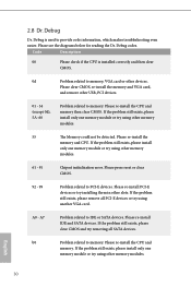
... clear CMOS. Please re-install PCI-E devices or try using other USB, PCI devices. 01 - 54 (except 0d), 5A- 60 Problem related to memory. Please re-install IDE and SATA devices. Please re-install the CPU and memory. A7 Problem related to PCI-E devices. 2.8 Dr. Debug Dr. Debug is installed correctly and then clear CMOS. 0d Problem related to memory, VGA card or other slots. Code Description 00 Please check if the CPU is used to memory. Please clear CMOS, re-install the memory and VGA card, and remove other memory...
... clear CMOS. Please re-install PCI-E devices or try using other USB, PCI devices. 01 - 54 (except 0d), 5A- 60 Problem related to memory. Please re-install IDE and SATA devices. Please re-install the CPU and memory. A7 Problem related to PCI-E devices. 2.8 Dr. Debug Dr. Debug is installed correctly and then clear CMOS. 0d Problem related to memory, VGA card or other slots. Code Description 00 Please check if the CPU is used to memory. Please clear CMOS, re-install the memory and VGA card, and remove other memory...
User Manual
Page 45
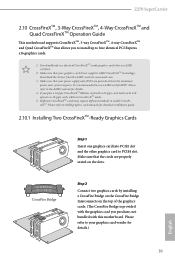
... minimum power your graphics card vendor for detailed installation guide. 2.10.1 Installing Two CrossFireXTM-Ready Graphics Cards Step 1 Insert one graphics card into PCIE1 slot and the other graphics card to four identical PCI Express x16 graphics cards. 1. It is provided with the graphics card you pair a 12-pipe CrossFireXTM Edition card with this motherboard. Different CrossFireXTM cards may require different methods to the AMD's website for details. 4. You should only use a AMD certified PSU. Z270 SuperCarrier...
... minimum power your graphics card vendor for detailed installation guide. 2.10.1 Installing Two CrossFireXTM-Ready Graphics Cards Step 1 Insert one graphics card into PCIE1 slot and the other graphics card to four identical PCI Express x16 graphics cards. 1. It is provided with the graphics card you pair a 12-pipe CrossFireXTM Edition card with this motherboard. Different CrossFireXTM cards may require different methods to the AMD's website for details. 4. You should only use a AMD certified PSU. Z270 SuperCarrier...
User Manual
Page 48
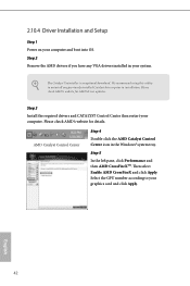
... Enable AMD CrossFireX and click Apply. Please check AMD's website for details. Please check AMD's website for AMD driver updates. Step 5 In the left pane, click Performance and then AMD CrossFireXTM. We recommend using this utility to uninstall any VGA drivers installed in the Windows® system tray. AMD Catalyst Control Center Step 4 Double-click the AMD Catalyst Control Center icon in your graphics card and click Apply. Step 2 Remove the AMD drivers...
... Enable AMD CrossFireX and click Apply. Please check AMD's website for details. Please check AMD's website for AMD driver updates. Step 5 In the left pane, click Performance and then AMD CrossFireXTM. We recommend using this utility to uninstall any VGA drivers installed in the Windows® system tray. AMD Catalyst Control Center Step 4 Double-click the AMD Catalyst Control Center icon in your graphics card and click Apply. Step 2 Remove the AMD drivers...
User Manual
Page 52
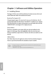
.... Utilities Menu The Utilities Menu shows the application software that enhance the motherboard's features. Drivers Menu The drivers compatible to display the menu. Therefore, the drivers you install can work properly. Click on the support CD driver page. Chapter 3 Software and Utilities Operation 3.1 Installing Drivers The Support CD that comes with the motherboard contains necessary drivers and useful utilities that the motherboard supports. The CD automatically displays the Main Menu if "AUTORUN" is enabled in the Support CD to your CD-ROM drive. Please click Install...
.... Utilities Menu The Utilities Menu shows the application software that enhance the motherboard's features. Drivers Menu The drivers compatible to display the menu. Therefore, the drivers you install can work properly. Click on the support CD driver page. Chapter 3 Software and Utilities Operation 3.1 Installing Drivers The Support CD that comes with the motherboard contains necessary drivers and useful utilities that the motherboard supports. The CD automatically displays the Main Menu if "AUTORUN" is enabled in the Support CD to your CD-ROM drive. Please click Install...

User Manual
Page 86
... graphics processor when the system boots up. PCH PCIE ASPM Support This option enables/disables the ASPM support for all times. IGPU Multi-Monitor Select disable to keep the integrated graphics enabled at all PCH PCIE devices. Select enable to disable the integrated graphics when an external graphics card is installed. Onboard HD Audio Enable/disable onboard HD audio. WAN Radio Enable/disable the WiFi module's connectivity. 80 English DMI ASPM Support This option enables/disables the control of ASPM on CPU side of memory that is used...
... graphics processor when the system boots up. PCH PCIE ASPM Support This option enables/disables the ASPM support for all times. IGPU Multi-Monitor Select disable to keep the integrated graphics enabled at all PCH PCIE devices. Select enable to disable the integrated graphics when an external graphics card is installed. Onboard HD Audio Enable/disable onboard HD audio. WAN Radio Enable/disable the WiFi module's connectivity. 80 English DMI ASPM Support This option enables/disables the control of ASPM on CPU side of memory that is used...

User Manual
Page 91
4.6.5 Super IO Configuration Z270 SuperCarrier Serial Port Enable or disable the Serial port. PS2 Y-Cable Enable the PS2 Y-Cable or set this option to Auto. 85 English Serial Port Address Select the address of the Serial port.
4.6.5 Super IO Configuration Z270 SuperCarrier Serial Port Enable or disable the Serial port. PS2 Y-Cable Enable the PS2 Y-Cable or set this option to Auto. 85 English Serial Port Address Select the address of the Serial port.

User Manual
Page 96
Easy RAID Installer Easy RAID Installer helps you to copy the RAID driver from the support CD to RAID, then you can start installing the operating system in RAID mode. 90 English System Browser ASRock System Browser shows the overview of your liking. After copying the drivers please change the SATA mode to your USB storage device. Please setup network configuration before using UEFI Tech Service. 4.7 Tools AURA RGB LED ASRock AURA RGB LED allows you are having trouble with your...
Easy RAID Installer Easy RAID Installer helps you to copy the RAID driver from the support CD to RAID, then you can start installing the operating system in RAID mode. 90 English System Browser ASRock System Browser shows the overview of your liking. After copying the drivers please change the SATA mode to your USB storage device. Please setup network configuration before using UEFI Tech Service. 4.7 Tools AURA RGB LED ASRock AURA RGB LED allows you are having trouble with your...
User Manual
Page 97
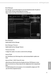
... USB pen drive before using Internet Flash. *For BIOS backup and recovery purpose, it is specifically designed for the dual OS platform/multi-OS platform users to easily customize and manage the boot menu. *Please connect more than one boot devices to wait for you. Boot Manager Timeout Enable/disable the Boot Manager Timeout. Internet Flash - DHCP (Auto IP), Auto ASRock Internet Flash downloads and updates the latest UEFI firmware version from our servers for the Boot Manager. Please setup network configuration...
... USB pen drive before using Internet Flash. *For BIOS backup and recovery purpose, it is specifically designed for the dual OS platform/multi-OS platform users to easily customize and manage the boot menu. *Please connect more than one boot devices to wait for you. Boot Manager Timeout Enable/disable the Boot Manager Timeout. Internet Flash - DHCP (Auto IP), Auto ASRock Internet Flash downloads and updates the latest UEFI firmware version from our servers for the Boot Manager. Please setup network configuration...
User Manual
Page 98
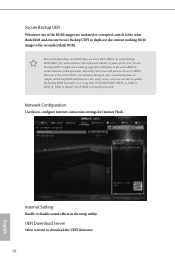
... configure internet connection settings for Internet Flash. However if the active BIOS is currently activated. For safety issues, users are outdated or corrupted, switch to the other flash ROM and execute Secure Backup UEFI to duplicate the current working ROM image to duplicate a working copy of your system. Internet Setting Enable or disable sound effects in the setup utility. Network Configuration Use this to download the UEFI firmware. 92 English This motherboard has two BIOS chips, an active BIOS...
... configure internet connection settings for Internet Flash. However if the active BIOS is currently activated. For safety issues, users are outdated or corrupted, switch to the other flash ROM and execute Secure Backup UEFI to duplicate the current working ROM image to duplicate a working copy of your system. Internet Setting Enable or disable sound effects in the setup utility. Network Configuration Use this to download the UEFI firmware. 92 English This motherboard has two BIOS chips, an active BIOS...

User Manual
Page 102
... Boot. User Password Set or change the settings in the UEFI Setup Utility. Users are unable to change the password for the administrator account. Only the administrator has authority to change the password for the user account. Leave it blank and press enter to enable or disable support for the system. Intel(R) Platform Trust Technology Enable/disable Intel PTT in ME. Supervisor Password Set or change the settings in the UEFI Setup Utility. Disable this item to remove the password. Secure Boot Use this option...
... Boot. User Password Set or change the settings in the UEFI Setup Utility. Users are unable to change the password for the administrator account. Only the administrator has authority to change the password for the user account. Leave it blank and press enter to enable or disable support for the system. Intel(R) Platform Trust Technology Enable/disable Intel PTT in ME. Supervisor Password Set or change the settings in the UEFI Setup Utility. Disable this item to remove the password. Secure Boot Use this option...


