
User Manual
Page 2
...for loss of profits, loss of business, loss of data, interruption of business and the like), even if ASRock has been advised of the possibility of merchantability or fitness for informational use only and subject to the following two conditions: ...(1) this documentation, ASRock does not provide warranty of ASRock Inc. ASRock assumes no event shall ASRock, its directors, officers, employees, or agents be reproduced, transcribed, transmitted, or translated in any language, in this motherboard contains Perchlorate, a toxic substance controlled in ...
...for loss of profits, loss of business, loss of data, interruption of business and the like), even if ASRock has been advised of the possibility of merchantability or fitness for informational use only and subject to the following two conditions: ...(1) this documentation, ASRock does not provide warranty of ASRock Inc. ASRock assumes no event shall ASRock, its directors, officers, employees, or agents be reproduced, transcribed, transmitted, or translated in any language, in this motherboard contains Perchlorate, a toxic substance controlled in ...

User Manual
Page 4
Contents Chapter 1 Introduction 1 1.1 Package Contents 1 1.2 Specifications 2 1.3 Motherboard Layout 8 1.4 I/O Panel 10 1.5 WiFi-802.11ac Module and ASRock WiFi 2.4/5 GHz Antenna 13 Chapter 2 Installation 15 2.1 Installing the CPU 16 2.2 Installing the CPU Fan and Heatsink 19 2.3 Installing Memory Modules (DIMM) 20 2.4 Expansion Slots (...
Contents Chapter 1 Introduction 1 1.1 Package Contents 1 1.2 Specifications 2 1.3 Motherboard Layout 8 1.4 I/O Panel 10 1.5 WiFi-802.11ac Module and ASRock WiFi 2.4/5 GHz Antenna 13 Chapter 2 Installation 15 2.1 Installing the CPU 16 2.2 Installing the CPU Fan and Heatsink 19 2.3 Installing Memory Modules (DIMM) 20 2.4 Expansion Slots (...
User Manual
Page 7
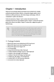
... documentation will be subject to change without further notice. ASRock website http://www.asrock.com. 1.1 Package Contents • ASRock Z270 SuperCarrier Motherboard (ATX Form Factor) • ASRock Z270 SuperCarrier Quick Installation Guide • ASRock Z270 SuperCarrier Support CD • 1 x I/O Panel Shield • 4 x Serial ATA (SATA) Data Cables (Optional) • 1 x ASRock Flexible SLI Bridge Connector Cable (Optional) • 1 x ASRock 3-Way SLI Bridge Card (Optional) •...
... documentation will be subject to change without further notice. ASRock website http://www.asrock.com. 1.1 Package Contents • ASRock Z270 SuperCarrier Motherboard (ATX Form Factor) • ASRock Z270 SuperCarrier Quick Installation Guide • ASRock Z270 SuperCarrier Support CD • 1 x I/O Panel Shield • 4 x Serial ATA (SATA) Data Cables (Optional) • 1 x ASRock Flexible SLI Bridge Connector Cable (Optional) • 1 x ASRock 3-Way SLI Bridge Card (Optional) •...

User Manual
Page 14
1.3 Motherboard Layout 1 2 3 45 USB 2.0 T: USB1 B: USB2 PS2 Keyboard /Mouse ATX12V1 CLRBTN1 CPU_OPT/W_PUMP M2_WIFI_1 RoHS XMP_ON1 CPU_FAN1 ON 6 OFF DISPLAYI_1 HDMI_1 DDR4_A1 (64 bit, 288-pin ... 8 9 10 Top: USB3_7_8 USB3_5_6 Center: FRONT Bottom: MIC IN PCIE1 1 1 SATA_EXP0_1 CMOS Battery 11 PCIE2 Intel Z270 PCIE3 CT24 CT23 CT22 CT21 12 M2_1 SATA3_A3_A4 SATA3_A1_A2 SATA3_4_5 GFX_12V1 Ultra M.2 PCIe Gen3 x4 M2_3 PCIE4 Z270 SUPER CARRIER CT34 CT33 CT32 CT31 CT14 CT13 CT12 CT 11 M2_2 HD_AUDIO1 HD_AUDIO_RA1 1 1 CLRMOS1 1 TPMS1 PCIE5...
1.3 Motherboard Layout 1 2 3 45 USB 2.0 T: USB1 B: USB2 PS2 Keyboard /Mouse ATX12V1 CLRBTN1 CPU_OPT/W_PUMP M2_WIFI_1 RoHS XMP_ON1 CPU_FAN1 ON 6 OFF DISPLAYI_1 HDMI_1 DDR4_A1 (64 bit, 288-pin ... 8 9 10 Top: USB3_7_8 USB3_5_6 Center: FRONT Bottom: MIC IN PCIE1 1 1 SATA_EXP0_1 CMOS Battery 11 PCIE2 Intel Z270 PCIE3 CT24 CT23 CT22 CT21 12 M2_1 SATA3_A3_A4 SATA3_A1_A2 SATA3_4_5 GFX_12V1 Ultra M.2 PCIe Gen3 x4 M2_3 PCIE4 Z270 SUPER CARRIER CT34 CT33 CT32 CT31 CT14 CT13 CT12 CT 11 M2_2 HD_AUDIO1 HD_AUDIO_RA1 1 1 CLRMOS1 1 TPMS1 PCIE5...

User Manual
Page 19
WiFi + BT Module (pre-installed Intel® Dual Band Wireless-AC 3160) ASRock WiFi 2.4/5 GHz Antennas (included in the package) 13 English BT 4.0 also includes Low Energy Technology and ensures extraordinary low power consumption for WiFi 802.11 a/b/ ... WiFi + BT. WiFi + BT module is an easy-touse wireless local area network (WLAN) adapter to the environment. Z270 SuperCarrier 1.5 WiFi-802.11ac Module and ASRock WiFi 2.4/5 GHz Antenna WiFi-802.11ac + BT Module This motherboard comes with an exclusive WiFi 802.11 a/b/g/n/ac + BT v4.0 module (pre-installed on the rear I/O panel) that...
WiFi + BT Module (pre-installed Intel® Dual Band Wireless-AC 3160) ASRock WiFi 2.4/5 GHz Antennas (included in the package) 13 English BT 4.0 also includes Low Energy Technology and ensures extraordinary low power consumption for WiFi 802.11 a/b/ ... WiFi + BT. WiFi + BT module is an easy-touse wireless local area network (WLAN) adapter to the environment. Z270 SuperCarrier 1.5 WiFi-802.11ac Module and ASRock WiFi 2.4/5 GHz Antenna WiFi-802.11ac + BT Module This motherboard comes with an exclusive WiFi 802.11 a/b/g/n/ac + BT v4.0 module (pre-installed on the rear I/O panel) that...
User Manual
Page 21
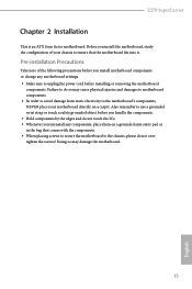
... it. Failure to do not touch the ICs. • Whenever you install motherboard components or change any components, place them on a carpet. Z270 SuperCarrier Chapter 2 Installation This is an ATX form factor motherboard. Doing so may cause physical injuries and damages to motherboard components. • In order to avoid damage from static electricity to use...
... it. Failure to do not touch the ICs. • Whenever you install motherboard components or change any components, place them on a carpet. Z270 SuperCarrier Chapter 2 Installation This is an ATX form factor motherboard. Doing so may cause physical injuries and damages to motherboard components. • In order to avoid damage from static electricity to use...

User Manual
Page 24
Please save and replace the cover if the processor is removed. The cover must be placed if you wish to return the motherboard for after service. 18 English
Please save and replace the cover if the processor is removed. The cover must be placed if you wish to return the motherboard for after service. 18 English

User Manual
Page 26
...pairs. 2. It is unable to install a DDR, DDR2 or DDR3 memory module into the slot at incorrect orientation. otherwise, this motherboard and DIMM may be damaged. English 20 It is not allowed to activate Dual Channel Memory Technology with only one correct orientation. 2.3 ...Installing Memory Modules (DIMM) This motherboard provides four 288-pin DDR4 (Double Data Rate 4) DIMM slots, and supports Dual Channel Memory Technology. 1. For dual channel configuration, ...
...pairs. 2. It is unable to install a DDR, DDR2 or DDR3 memory module into the slot at incorrect orientation. otherwise, this motherboard and DIMM may be damaged. English 20 It is not allowed to activate Dual Channel Memory Technology with only one correct orientation. 2.3 ...Installing Memory Modules (DIMM) This motherboard provides four 288-pin DDR4 (Double Data Rate 4) DIMM slots, and supports Dual Channel Memory Technology. 1. For dual channel configuration, ...

User Manual
Page 28
2.4 Expansion Slots (PCI Express Slots) There are 5 PCI Express slots on the motherboard. PCIe slots: PCIE1 (PCIe 3.0 x16 slot) is used for PCI Express x8 lane width graphics cards. PCIE5 (PCIe 3.0 x16 slot) is used for PCI Express ... x16 Four Graphics Cards in CrossFireXTM or SLITM x8 x8 x8 Mode PCIE5 N/A N/A N/A x8 English For a better thermal environment, please connect a chassis fan to the motherboard's chassis fan connector (CHA_FAN1, CHA_FAN2 or CHA_FAN3 ) when using multiple graphics cards. 22 PCIE4 (PCIe 3.0 x16 slot) is used for PCI Express x1 lane width...
2.4 Expansion Slots (PCI Express Slots) There are 5 PCI Express slots on the motherboard. PCIe slots: PCIE1 (PCIe 3.0 x16 slot) is used for PCI Express x8 lane width graphics cards. PCIE5 (PCIe 3.0 x16 slot) is used for PCI Express ... x16 Four Graphics Cards in CrossFireXTM or SLITM x8 x8 x8 Mode PCIE5 N/A N/A N/A x8 English For a better thermal environment, please connect a chassis fan to the motherboard's chassis fan connector (CHA_FAN1, CHA_FAN2 or CHA_FAN3 ) when using multiple graphics cards. 22 PCIE4 (PCIe 3.0 x16 slot) is used for PCI Express x1 lane width...

User Manual
Page 30
... cause permanent damage to turn off (S5). The LED is on the chassis front panel. The front panel design may configure the way to the motherboard. The LED is on the chassis front panel. English 24 2.6 Onboard Headers and Connectors Onboard headers and connectors are matched correctly. Placing jumper caps over...
... cause permanent damage to turn off (S5). The LED is on the chassis front panel. The front panel design may configure the way to the motherboard. The LED is on the chassis front panel. English 24 2.6 Onboard Headers and Connectors Onboard headers and connectors are matched correctly. Placing jumper caps over...
User Manual
Page 32
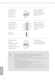
... HD_AUDIO1) (see p.8, No. 30) (9-pin HD_AUDIO_RA1) (see p.8, No. 8) USB_PWR PP+ GND DUMMY 1 GND P+ PUSB_PWR There are two headers on this motherboard. Connect Mic_IN (MIC) to OUT2_L. Connect Audio_R (RIN) to OUT2_R and Audio_L (LIN) to MIC2_L. E. Please follow the instructions in the Realtek Control panel ..." Tab in our manual and chassis manual to Ground (GND). D. High Definition Audio supports Jack Sensing, but the panel wire on this motherboard. B. Each USB 2.0 header can support two ports. MIC_RET and OUT_RET are two headers and one port on the chassis must support HDA ...
... HD_AUDIO1) (see p.8, No. 30) (9-pin HD_AUDIO_RA1) (see p.8, No. 8) USB_PWR PP+ GND DUMMY 1 GND P+ PUSB_PWR There are two headers on this motherboard. Connect Mic_IN (MIC) to OUT2_L. Connect Audio_R (RIN) to OUT2_R and Audio_L (LIN) to MIC2_L. E. Please follow the instructions in the Realtek Control panel ..." Tab in our manual and chassis manual to Ground (GND). D. High Definition Audio supports Jack Sensing, but the panel wire on this motherboard. B. Each USB 2.0 header can support two ports. MIC_RET and OUT_RET are two headers and one port on the chassis must support HDA ...

User Manual
Page 33
.... 20) CPU Fan Connector (4-pin CPU_FAN1) (see p.8, No. 2) FAN_SPEED_CONTROL FAN_SPEED FAN_VOLTAGE GND 4 This motherboard 3 2 provides a 4-Pin water 1 cooling CPU fan connector. To use a 20-pin ATX power supply, please plug it to Pin 1-3. Z270 SuperCarrier Chassis Optional/Water This motherboard Pump Fan Connector provides two 4-Pin water (4-pin CHA_FAN1/W_ cooling chassis fan PUMP...
.... 20) CPU Fan Connector (4-pin CPU_FAN1) (see p.8, No. 2) FAN_SPEED_CONTROL FAN_SPEED FAN_VOLTAGE GND 4 This motherboard 3 2 provides a 4-Pin water 1 cooling CPU fan connector. To use a 20-pin ATX power supply, please plug it to Pin 1-3. Z270 SuperCarrier Chassis Optional/Water This motherboard Pump Fan Connector provides two 4-Pin water (4-pin CHA_FAN1/W_ cooling chassis fan PUMP...

User Manual
Page 34
...pin TPMS1) (see p.8, No. 27) AURA RGB LED Header (4-pin RGB_LED) (see p.8, No. 26) 8 5 4 1 4 1 6 3 This motherboard provides a 8-pin ATX 12V power connector. Caution: Never install the RGB LED cable in the wrong orientation; To use a 4-pin ATX power supply, please...R B AURA RGB LED header is used to connect RGB LED extension cable which can securely store keys, digital certificates, passwords, and data. This motherboard provides a 6-pin Graphics 12V power connector. * Install the PSU's power cable to choose from various LED lighting effects. ATX 12V Power Connector (8-pin...
...pin TPMS1) (see p.8, No. 27) AURA RGB LED Header (4-pin RGB_LED) (see p.8, No. 26) 8 5 4 1 4 1 6 3 This motherboard provides a 8-pin ATX 12V power connector. Caution: Never install the RGB LED cable in the wrong orientation; To use a 4-pin ATX power supply, please...R B AURA RGB LED header is used to connect RGB LED extension cable which can securely store keys, digital certificates, passwords, and data. This motherboard provides a 6-pin Graphics 12V power connector. * Install the PSU's power cable to choose from various LED lighting effects. ATX 12V Power Connector (8-pin...

User Manual
Page 35
... CMOS values. XMP Switch (XMP_ON1) (see p.10, No. 19) Clear CMOS Switch allows users to automatically configure the overclocked DRAM voltages for stable operation. Z270 SuperCarrier 2.7 Smart Switches The motherboard has four smart switches: Power Switch, Reset Switch, Clear CMOS Switch and XMP Switch. Reset Switch (RSTBTN1) (see p.8, No. 17) Power Power Switch...
... CMOS values. XMP Switch (XMP_ON1) (see p.10, No. 19) Clear CMOS Switch allows users to automatically configure the overclocked DRAM voltages for stable operation. Z270 SuperCarrier 2.7 Smart Switches The motherboard has four smart switches: Power Switch, Reset Switch, Clear CMOS Switch and XMP Switch. Reset Switch (RSTBTN1) (see p.8, No. 17) Power Power Switch...

User Manual
Page 38
... sure that the cards are NVIDIA® certi- Make sure that your system requires. 2.9 SLITM , 3-Way SLITM , 4-Way SLITM and Quad SLITM Operation Guide This motherboard supports NVIDIA® SLITM , 3-way SLITM, 4-way SLITM and Quad SLITM (Scalable Link Interface) technology that allows you to install up to use identical SLITM...
... sure that the cards are NVIDIA® certi- Make sure that your system requires. 2.9 SLITM , 3-Way SLITM , 4-Way SLITM and Quad SLITM Operation Guide This motherboard supports NVIDIA® SLITM , 3-way SLITM, 4-way SLITM and Quad SLITM (Scalable Link Interface) technology that allows you to install up to use identical SLITM...
User Manual
Page 45
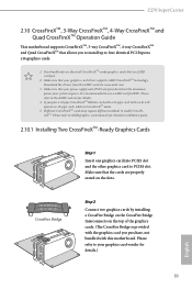
...PSU) can provide at least the minimum power your graphics card vendor for details.) English 39 Z270 SuperCarrier 2.10 CrossFireXTM, 3-Way CrossFireXTM, 4-Way CrossFireXTM and Quad CrossFireXTM Operation Guide This motherboard supports CrossFireXTM, 3-way CrossFireXTM, 4-way CrossFireXTM and Quad CrossFireXTM that allows you pair a 12-...pipe CrossFireXTM Edition card with this motherboard. Download the drivers from the AMD's website: www.amd.com 3. Make sure that the cards are AMD certified. ...
...PSU) can provide at least the minimum power your graphics card vendor for details.) English 39 Z270 SuperCarrier 2.10 CrossFireXTM, 3-Way CrossFireXTM, 4-Way CrossFireXTM and Quad CrossFireXTM Operation Guide This motherboard supports CrossFireXTM, 3-way CrossFireXTM, 4-way CrossFireXTM and Quad CrossFireXTM that allows you pair a 12-...pipe CrossFireXTM Edition card with this motherboard. Download the drivers from the AMD's website: www.amd.com 3. Make sure that the cards are AMD certified. ...

User Manual
Page 46
... to connect the graphics cards on PCIE2 and PCIE4 slots. (The CrossFire Bridge is provided with the graphics card you purchase, not bundled with this motherboard. Step 3 Connect a VGA cable or a DVI cable to the monitor connector or the DVI connector of the graphics card that the cards are properly seated...
... to connect the graphics cards on PCIE2 and PCIE4 slots. (The CrossFire Bridge is provided with the graphics card you purchase, not bundled with this motherboard. Step 3 Connect a VGA cable or a DVI cable to the monitor connector or the DVI connector of the graphics card that the cards are properly seated...

User Manual
Page 47
... into PCIE1 slot, another CrossFire Bridge to connect the graphics cards on PCIE2 and PCIE4 slots, and use the third CrossFire Bridge to PCIE1 slot. Z270 SuperCarrier 2.10.3 Installing Four CrossFireXTM-Ready Graphics Cards Step 1 Insert one CrossFire Bridge to connect the graphics cards on PCIE1 and PCIE2 slots, another graphics card... connect the Radeon graphics cards on PCIE4 and PCIE5 slots. (The CrossFire Bridge is provided with the graphics card you purchase, not bundled with this motherboard.
... into PCIE1 slot, another CrossFire Bridge to connect the graphics cards on PCIE2 and PCIE4 slots, and use the third CrossFire Bridge to PCIE1 slot. Z270 SuperCarrier 2.10.3 Installing Four CrossFireXTM-Ready Graphics Cards Step 1 Insert one CrossFire Bridge to connect the graphics cards on PCIE1 and PCIE2 slots, another graphics card... connect the Radeon graphics cards on PCIE4 and PCIE5 slots. (The CrossFire Bridge is provided with the graphics card you purchase, not bundled with this motherboard.

User Manual
Page 50
... be used. Please do not overtighten the screw as this might damage the module. English 44 Step 4 Peel off the yellow protective film on the motherboard. Step 5 Align and gently insert the M.2 (NGFF) SSD module into place. Step 6 Tighten the screw with a screwdriver to secure the module into the M.2 slot. The...
... be used. Please do not overtighten the screw as this might damage the module. English 44 Step 4 Peel off the yellow protective film on the motherboard. Step 5 Align and gently insert the M.2 (NGFF) SSD module into place. Step 6 Tighten the screw with a screwdriver to secure the module into the M.2 slot. The...
User Manual
Page 52
Utilities Menu The Utilities Menu shows the application software that enhance the motherboard's features. Chapter 3 Software and Utilities Operation 3.1 Installing Drivers The Support CD that comes with the motherboard contains necessary drivers and useful utilities that the motherboard supports. Please click Install All or follow the installation wizard to your computer. To improve Windows...
Utilities Menu The Utilities Menu shows the application software that enhance the motherboard's features. Chapter 3 Software and Utilities Operation 3.1 Installing Drivers The Support CD that comes with the motherboard contains necessary drivers and useful utilities that the motherboard supports. Please click Install All or follow the installation wizard to your computer. To improve Windows...


