User Manual
Page 5
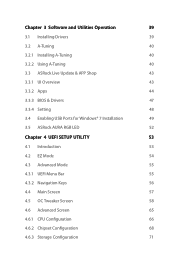
... Update & APP Shop 43 3.3.1 UI Overview 43 3.3.2 Apps 44 3.3.3 BIOS & Drivers 47 3.3.4 Setting 48 3.4 Enabling USB Ports for Windows® 7 Installation 49 3.5 ASRock AURA RGB LED 52 Chapter 4 UEFI SETUP UTILITY 53 4.1 Introduction 53 4.2 EZ Mode 54 4.3 Advanced Mode 55 4.3.1 UEFI Menu Bar 55 4.3.2 Navigation Keys 56 4.4 Main Screen 57 4.5 OC ...
... Update & APP Shop 43 3.3.1 UI Overview 43 3.3.2 Apps 44 3.3.3 BIOS & Drivers 47 3.3.4 Setting 48 3.4 Enabling USB Ports for Windows® 7 Installation 49 3.5 ASRock AURA RGB LED 52 Chapter 4 UEFI SETUP UTILITY 53 4.1 Introduction 53 4.2 EZ Mode 54 4.3 Advanced Mode 55 4.3.1 UEFI Menu Bar 55 4.3.2 Navigation Keys 56 4.4 Main Screen 57 4.5 OC ...

User Manual
Page 10
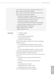
...for R/L Audio Channel - AURA RGB LED • Supports DTS Connect LAN • Gigabit LAN 10/100/1000 Mb/s • Giga PHY Intel® I219V • Supports Wake-On-LAN • Supports Lightning/ESD Protection (ASRock Full Spike Protection) • Supports ...USB 3.1 Type-C Port (10 Gb/s) (ASMedia ASM2142) (Supports ESD Protection (ASRock Full Spike Protection)) • 4 x USB 3.0 Ports (Intel® Z270) (Supports ESD Protection (ASRock Full Spike Protection)) • 1 x RJ-45 LAN Port with LED (ACT/LINK LED and SPEED LED) • HD Audio Jacks: Rear Speaker / Central / Bass / Line...
...for R/L Audio Channel - AURA RGB LED • Supports DTS Connect LAN • Gigabit LAN 10/100/1000 Mb/s • Giga PHY Intel® I219V • Supports Wake-On-LAN • Supports Lightning/ESD Protection (ASRock Full Spike Protection) • Supports ...USB 3.1 Type-C Port (10 Gb/s) (ASMedia ASM2142) (Supports ESD Protection (ASRock Full Spike Protection)) • 4 x USB 3.0 Ports (Intel® Z270) (Supports ESD Protection (ASRock Full Spike Protection)) • 1 x RJ-45 LAN Port with LED (ACT/LINK LED and SPEED LED) • HD Audio Jacks: Rear Speaker / Central / Bass / Line...
User Manual
Page 11
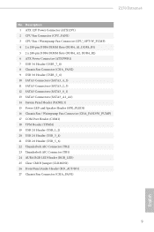
... (10-pin) * Only one Thunderbolt AIC Card is in use , the others will be disabled. * M2_2, SATA3_4 and SATA3_5 share lanes. Z270 Extreme4 * M2_1, SATA3_0 and SATA3_1 share lanes. If either one of them is supported English 5 If either one of them is in use , the.../s)** ** Supports Intel® OptaneTM Technology ** Supports NVMe SSD as boot disks ** Supports ASRock U.2 Kit Connector • 1 x COM Port Header • 1 x TPM Header • 1 x Power LED and Speaker Header • 1 x AURA RGB LED Header • 1 x CPU Fan Connector (4-pin) * The CPU Fan Connector supports ...
... (10-pin) * Only one Thunderbolt AIC Card is in use , the others will be disabled. * M2_2, SATA3_4 and SATA3_5 share lanes. Z270 Extreme4 * M2_1, SATA3_0 and SATA3_1 share lanes. If either one of them is supported English 5 If either one of them is in use , the.../s)** ** Supports Intel® OptaneTM Technology ** Supports NVMe SSD as boot disks ** Supports ASRock U.2 Kit Connector • 1 x COM Port Header • 1 x TPM Header • 1 x Power LED and Speaker Header • 1 x AURA RGB LED Header • 1 x CPU Fan Connector (4-pin) * The CPU Fan Connector supports ...
User Manual
Page 15
...SATA3 Connectors (SATA3_4_5) 11 SATA3 Connectors (SATA3_2_3) 12 SATA3 Connectors (SATA3_0_1) 13 SATA3 Connectors (SATA3_A1_A2) 14 System Panel Header (PANEL1) 15 Power LED and Speaker Header (SPK_PLED1) 16 Chassis Fan / Waterpump Fan Connector (CHA_FAN3/W_PUMP) 17 COM Port Header (COM1) 18 TPM Header (TPMS1) 19 ... Header (USB_3_4) 21 USB 2.0 Header (USB_5_6) 22 Thunderbolt AIC Connector (TB2) 23 Thunderbolt AIC Connector (TB1) 24 AURA RGB LED Header (RGB_LED) 25 Clear CMOS Jumper (CLRMOS1) 26 Front Panel Audio Header (HD_AUDIO1) 27 Chassis Fan Connector (CHA_FAN1) 9 English Z270 Extreme4 No.
...SATA3 Connectors (SATA3_4_5) 11 SATA3 Connectors (SATA3_2_3) 12 SATA3 Connectors (SATA3_0_1) 13 SATA3 Connectors (SATA3_A1_A2) 14 System Panel Header (PANEL1) 15 Power LED and Speaker Header (SPK_PLED1) 16 Chassis Fan / Waterpump Fan Connector (CHA_FAN3/W_PUMP) 17 COM Port Header (COM1) 18 TPM Header (TPMS1) 19 ... Header (USB_3_4) 21 USB 2.0 Header (USB_5_6) 22 Thunderbolt AIC Connector (TB2) 23 Thunderbolt AIC Connector (TB1) 24 AURA RGB LED Header (RGB_LED) 25 Clear CMOS Jumper (CLRMOS1) 26 Front Panel Audio Header (HD_AUDIO1) 27 Chassis Fan Connector (CHA_FAN1) 9 English Z270 Extreme4 No.

User Manual
Page 17
English 11 Z270 Extreme4 * There are allowed to select "Realtek HDA Primary output" to use the Rear Speaker, Central/Bass, and Front Speaker, or select "Realtek HDA Audio 2nd ..., you need to connect a front panel audio cable to the table below for the LAN port LED indications. ACT/LINK LED SPEED LED LAN Port Activity / Link LED Status Off Blinking On Description No Link Data Activity Link Speed LED Status Off Orange Green Description 10Mbps connection 100Mbps connection 1Gbps connection ** If you use. See...
English 11 Z270 Extreme4 * There are allowed to select "Realtek HDA Primary output" to use the Rear Speaker, Central/Bass, and Front Speaker, or select "Realtek HDA Audio 2nd ..., you need to connect a front panel audio cable to the table below for the LAN port LED indications. ACT/LINK LED SPEED LED LAN Port Activity / Link LED Status Off Blinking On Description No Link Data Activity Link Speed LED Status Off Orange Green Description 10Mbps connection 100Mbps connection 1Gbps connection ** If you use. See...
User Manual
Page 27
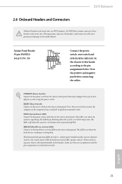
... on when the hard drive is operating. The LED is on when the system is reading or writing data. English 21 Z270 Extreme4 2.6 Onboard Headers and Connectors Onboard headers and connectors are matched correctly. Placing jumper caps over these headers and connectors. ...You may differ by chassis. Note the positive and negative pins before connecting the cables. The LED keeps blinking when the ...
... on when the hard drive is operating. The LED is on when the system is reading or writing data. English 21 Z270 Extreme4 2.6 Onboard Headers and Connectors Onboard headers and connectors are matched correctly. Placing jumper caps over these headers and connectors. ...You may differ by chassis. Note the positive and negative pins before connecting the cables. The LED keeps blinking when the ...
User Manual
Page 28
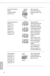
If either one of them is in use Intel® Z270 SATA ports (SATA3_0) for internal storage devices with up to this motherboard. English 22 Please connect the chassis power LED and the chassis speaker to 6.0 Gb/s data transfer rate. * M2_1, SATA3_0 and SATA3_1 share lanes. ...Each USB 2.0 header can support two ports. Power LED and Speaker Header (7-pin SPK_PLED1) (see p.8, No. 15) Serial ATA3 Connectors (SATA3_4_5: see p.8, No. 10) (SATA3_2_3: see p.8, No. 11) (SATA3_0_1: see ...
If either one of them is in use Intel® Z270 SATA ports (SATA3_0) for internal storage devices with up to this motherboard. English 22 Please connect the chassis power LED and the chassis speaker to 6.0 Gb/s data transfer rate. * M2_1, SATA3_0 and SATA3_1 share lanes. ...Each USB 2.0 header can support two ports. Power LED and Speaker Header (7-pin SPK_PLED1) (see p.8, No. 15) Serial ATA3 Connectors (SATA3_4_5: see p.8, No. 10) (SATA3_2_3: see p.8, No. 11) (SATA3_0_1: see ...
User Manual
Page 31
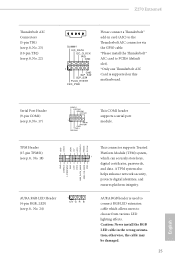
... in card (AIC) to the Thunderbolt AIC connector via the GPIO cable. *Please install the Thunderbolt™ AIC card to choose from various LED lighting effects. Z270 Extreme4 Thunderbolt AIC Connectors (5-pin TB1) (see p.8, No. 23) (10-pin TB2) (see p.8, No. 24) 1 12V G R B AURA ...RGB header is supported on this motherboard. AURA RGB LED Header (4-pin RGB_LED) (see p.8, No. 22) DUMMY I2C_DATA I2C_CLOCK IRQ GND 1 GND SLP_S4# SLP_S3# PLUG_EVENT FRC_PWR ...
... in card (AIC) to the Thunderbolt AIC connector via the GPIO cable. *Please install the Thunderbolt™ AIC card to choose from various LED lighting effects. Z270 Extreme4 Thunderbolt AIC Connectors (5-pin TB1) (see p.8, No. 23) (10-pin TB2) (see p.8, No. 24) 1 12V G R B AURA ...RGB header is supported on this motherboard. AURA RGB LED Header (4-pin RGB_LED) (see p.8, No. 22) DUMMY I2C_DATA I2C_CLOCK IRQ GND 1 GND SLP_S4# SLP_S3# PLUG_EVENT FRC_PWR ...

User Manual
Page 58
English 52 Drag the tab to build your preference. By connecting LED strip, you to customize your own colorful lighting system. Toggle on/off the RGB LED switch Apply the settings Select a RGB LED light effect from the drop-down menu. 3.5 ASRock AURA RGB LED ASRock AURA RGB LED allows you can adjust the RGB LED color through ASRock AURA RGB LED utility.
English 52 Drag the tab to build your preference. By connecting LED strip, you to customize your own colorful lighting system. Toggle on/off the RGB LED switch Apply the settings Select a RGB LED light effect from the drop-down menu. 3.5 ASRock AURA RGB LED ASRock AURA RGB LED allows you can adjust the RGB LED color through ASRock AURA RGB LED utility.
User Manual
Page 87
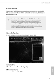
... BIOS. Internet Setting Enable or disable sound effects in the setup utility. Users may refer to the BIOS LEDs (BIOS_A_LED or BIOS_B_LED) to identify which enhances the safety and stability of your system. Z270 Extreme4 Secure Backup UEFI Whenever one of the ROM images are not able to update the backup BIOS manually.
... BIOS. Internet Setting Enable or disable sound effects in the setup utility. Users may refer to the BIOS LEDs (BIOS_A_LED or BIOS_B_LED) to identify which enhances the safety and stability of your system. Z270 Extreme4 Secure Backup UEFI Whenever one of the ROM images are not able to update the backup BIOS manually.
