User Manual
Page 7
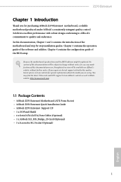
... to change without further notice. ASRock website http://www.asrock.com. 1.1 Package Contents • ASRock Z270 Extreme4 Motherboard (ATX Form Factor) • ASRock Z270 Extreme4 Quick Installation Guide • ASRock Z270 Extreme4 Support CD • 1 x I/O Panel Shield • 4 x Serial ATA (SATA) Data Cables (Optional) • 1 x ASRock SLI_HB_Bridge_2S Card (Optional) • 3 x Screws for purchasing ASRock Z270 Extreme4 motherboard, a reliable motherboard produced under ASRock's consistently stringent quality control. You...
... to change without further notice. ASRock website http://www.asrock.com. 1.1 Package Contents • ASRock Z270 Extreme4 Motherboard (ATX Form Factor) • ASRock Z270 Extreme4 Quick Installation Guide • ASRock Z270 Extreme4 Support CD • 1 x I/O Panel Shield • 4 x Serial ATA (SATA) Data Cables (Optional) • 1 x ASRock SLI_HB_Bridge_2S Card (Optional) • 3 x Screws for purchasing ASRock Z270 Extreme4 motherboard, a reliable motherboard produced under ASRock's consistently stringent quality control. You...
User Manual
Page 8
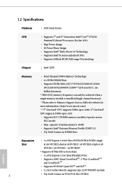
...Slots (PCIE2/PCIE4/PCIE6: single Slot at x8 (PCIE2) / x8 (PCIE4); dual at x16 (PCIE2); 1.2 Specifications Platform CPU Chipset • ATX Form Factor • Supports 7th and 6th Generation Intel® CoreTM i7/i5/i3/ Pentium®/Celeron® Processors (Socket 1151) • Digi... • Supports Intel® Turbo Boost 2.0 Technology • Supports Intel® K-Series unlocked CPUs • Supports ASRock BCLK Full-range Overclocking • Intel® Z270 Memory • Dual Channel DDR4 Memory Technology • 4 x DDR4 DIMM Slots • Supports DDR4 3866+(OC)*/3733...
...Slots (PCIE2/PCIE4/PCIE6: single Slot at x8 (PCIE2) / x8 (PCIE4); dual at x16 (PCIE2); 1.2 Specifications Platform CPU Chipset • ATX Form Factor • Supports 7th and 6th Generation Intel® CoreTM i7/i5/i3/ Pentium®/Celeron® Processors (Socket 1151) • Digi... • Supports Intel® Turbo Boost 2.0 Technology • Supports Intel® K-Series unlocked CPUs • Supports ASRock BCLK Full-range Overclocking • Intel® Z270 Memory • Dual Channel DDR4 Memory Technology • 4 x DDR4 DIMM Slots • Supports DDR4 3866+(OC)*/3733...
User Manual
Page 11
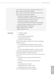
Z270 Extreme4 * M2_1, SATA3_0 and SATA3_1 share lanes. If either one Thunderbolt... and M.2 PCI Express module up to Gen3 x4 (32 Gb/s)** ** Supports Intel® OptaneTM Technology ** Supports NVMe SSD as boot disks ** Supports ASRock U.2 Kit Connector • 1 x COM Port Header • 1 x TPM Header • 1 x Power LED and Speaker Header • 1... fan power. * CHA_FAN1 and CHA_FAN2 can auto detect if 3-pin or 4-pin fan is in use. • 1 x 24 pin ATX Power Connector (Hi-Density Power Connector). • 1 x 8 pin 12V Power Connector (Hi-Density Power Connector) • 1 x Front...
Z270 Extreme4 * M2_1, SATA3_0 and SATA3_1 share lanes. If either one Thunderbolt... and M.2 PCI Express module up to Gen3 x4 (32 Gb/s)** ** Supports Intel® OptaneTM Technology ** Supports NVMe SSD as boot disks ** Supports ASRock U.2 Kit Connector • 1 x COM Port Header • 1 x TPM Header • 1 x Power LED and Speaker Header • 1... fan power. * CHA_FAN1 and CHA_FAN2 can auto detect if 3-pin or 4-pin fan is in use. • 1 x 24 pin ATX Power Connector (Hi-Density Power Connector). • 1 x 8 pin 12V Power Connector (Hi-Density Power Connector) • 1 x Front...
User Manual
Page 15
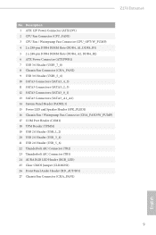
Z270 Extreme4 No. Description 1 ATX 12V Power Connector (ATX12V1) 2 CPU Fan Connector (CPU_FAN1) 3 CPU Fan / Waterpump Fan Connector (CPU_OPT/W_PUMP) 4 2 x 288-pin DDR4 DIMM Slots (DDR4_A1, DDR4_B1) 5 2 x 288-pin DDR4 DIMM Slots (DDR4_A2, DDR4_B2) 6 ATX Power Connector (ATXPWR1) 7 USB 3.0 Header (USB3_7_8) 8 Chassis Fan Connector (CHA_FAN2) 9 USB 3.0 Header (USB3_5_6) 10 SATA3 Connectors (SATA3_4_5) 11 SATA3 Connectors...
Z270 Extreme4 No. Description 1 ATX 12V Power Connector (ATX12V1) 2 CPU Fan Connector (CPU_FAN1) 3 CPU Fan / Waterpump Fan Connector (CPU_OPT/W_PUMP) 4 2 x 288-pin DDR4 DIMM Slots (DDR4_A1, DDR4_B1) 5 2 x 288-pin DDR4 DIMM Slots (DDR4_A2, DDR4_B2) 6 ATX Power Connector (ATXPWR1) 7 USB 3.0 Header (USB3_7_8) 8 Chassis Fan Connector (CHA_FAN2) 9 USB 3.0 Header (USB3_5_6) 10 SATA3 Connectors (SATA3_4_5) 11 SATA3 Connectors...
User Manual
Page 18
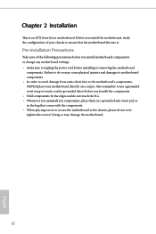
... before installing or removing the motherboard components. Before you install motherboard components or change any components, place them on a carpet. Chapter 2 Installation This is an ATX form factor motherboard. Failure to do not overtighten the screws!
... before installing or removing the motherboard components. Before you install motherboard components or change any components, place them on a carpet. Chapter 2 Installation This is an ATX form factor motherboard. Failure to do not overtighten the screws!

User Manual
Page 30
... p.8, No. 3) FAN_SPEED_CONTROL CPU_FAN_SPEED FAN_VOLTAGE GND This motherboard 4 3 provides a 4-Pin water 2 cooling CPU fan 1 connector. English 24 To use a 4-pin ATX power supply, please plug it to Pin 1-3. CPU Optional/Water Pump Fan Connector (4-pin CPU_OPT/W_ PUMP) (see p.8, No. 1) 8 5 This motherboard pro...CPU fan, please connect it along Pin 1 and Pin 13. ATX Power Connector (24-pin ATXPWR1) (see p.8, No. 6) 12 24 1 13 This motherboard provides a 24-pin ATX power connector. To use a 20-pin ATX power supply, please plug it to Pin 1-3. If you plan to...
... p.8, No. 3) FAN_SPEED_CONTROL CPU_FAN_SPEED FAN_VOLTAGE GND This motherboard 4 3 provides a 4-Pin water 2 cooling CPU fan 1 connector. English 24 To use a 4-pin ATX power supply, please plug it to Pin 1-3. CPU Optional/Water Pump Fan Connector (4-pin CPU_OPT/W_ PUMP) (see p.8, No. 1) 8 5 This motherboard pro...CPU fan, please connect it along Pin 1 and Pin 13. ATX Power Connector (24-pin ATXPWR1) (see p.8, No. 6) 12 24 1 13 This motherboard provides a 24-pin ATX power connector. To use a 20-pin ATX power supply, please plug it to Pin 1-3. If you plan to...
