
User Manual
Page 6
... CPU support list on ASRock's website without notice. Chapter 3 contains the operation guide of the BIOS setup. ASRock website http://www.asrock.com. 1.1 Package Contents • ASRock X99E-ITX/ac Motherboard (Mini-ITX Form Factor) • ASRock X99E-ITX/ac Quick Installation Guide • ASRock X99E-ITX/ac Support CD • ...• 2 x Screws for WiFi Module • 1 x Screw for purchasing ASRock X99E-ITX/ac motherboard, a reliable motherboard produced under ASRock's consistently stringent quality control. If you require technical support related to this documentation will...
... CPU support list on ASRock's website without notice. Chapter 3 contains the operation guide of the BIOS setup. ASRock website http://www.asrock.com. 1.1 Package Contents • ASRock X99E-ITX/ac Motherboard (Mini-ITX Form Factor) • ASRock X99E-ITX/ac Quick Installation Guide • ASRock X99E-ITX/ac Support CD • ...• 2 x Screws for WiFi Module • 1 x Screw for purchasing ASRock X99E-ITX/ac motherboard, a reliable motherboard produced under ASRock's consistently stringent quality control. If you require technical support related to this documentation will...

User Manual
Page 8
X99E-ITX/ac • TI® NE5532 Premium Headset Amplifier (Supports up to 600 Ohm headsets) • Supports DTS Connect LAN • Gigabit LAN 10/100/1000 Mb/s &#..., 1 x GigaLAN Intel® I211AT • Supports Intel® Remote Wake Technology (on Intel® I218V) • Supports Wake-On-LAN • Supports Lightning/ESD Protection (ASRock Full Spike Protection) • Supports Dual LAN with Teaming • Supports Energy Efficient Ethernet 802.3az • Supports PXE Wireless LAN • Supports IEEE 802...
X99E-ITX/ac • TI® NE5532 Premium Headset Amplifier (Supports up to 600 Ohm headsets) • Supports DTS Connect LAN • Gigabit LAN 10/100/1000 Mb/s &#..., 1 x GigaLAN Intel® I211AT • Supports Intel® Remote Wake Technology (on Intel® I218V) • Supports Wake-On-LAN • Supports Lightning/ESD Protection (ASRock Full Spike Protection) • Supports Dual LAN with Teaming • Supports Energy Efficient Ethernet 802.3az • Supports PXE Wireless LAN • Supports IEEE 802...
User Manual
Page 10
You can use ASRock XFast RAM to the components and devices of your system. It should be less than 4GB for the reservation for possible damage caused by overclocking. ... product information, please visit our website: http://www.asrock.com Please realize that Windows® cannot use. English 5 We are not responsible for system usage under Windows® 32-bit operating systems. Windows® 64-bit operating systems do not have such limitations. X99E-ITX/ac OS Certifications • CASE OPEN detection • Voltage...
You can use ASRock XFast RAM to the components and devices of your system. It should be less than 4GB for the reservation for possible damage caused by overclocking. ... product information, please visit our website: http://www.asrock.com Please realize that Windows® cannot use. English 5 We are not responsible for system usage under Windows® 32-bit operating systems. Windows® 64-bit operating systems do not have such limitations. X99E-ITX/ac OS Certifications • CASE OPEN detection • Voltage...
User Manual
Page 11
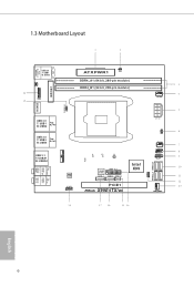
... PLED1 1 6 Ct1 CT2 Ct3 CPU_FAN1 7 USB3_4 8 1 PLED PWRBTN 1 9 HDLED RESET PANEL1 Intel 10 USB3_5_6 X99 128Mb BIOS SATA3_4 SATA3_5 SATAE_4_5 11 SPEAKER1 1 SATA3_2_3 SATA3_0_1 PCIE1 X99E-ITX/ac 12 13 CHA_FAN1 Bottom: Optical SPDIF 18 17 16 15 14 English 6
... PLED1 1 6 Ct1 CT2 Ct3 CPU_FAN1 7 USB3_4 8 1 PLED PWRBTN 1 9 HDLED RESET PANEL1 Intel 10 USB3_5_6 X99 128Mb BIOS SATA3_4 SATA3_5 SATAE_4_5 11 SPEAKER1 1 SATA3_2_3 SATA3_0_1 PCIE1 X99E-ITX/ac 12 13 CHA_FAN1 Bottom: Optical SPDIF 18 17 16 15 14 English 6
User Manual
Page 12
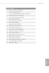
... Connector (SATAE_4_5) 16 SATA3 Connector (SATA3_5) 17 SATA3 Connector (SATA3_4) 18 Front Panel Audio Header (HD_AUDIO1) 19 Clear CMOS Jumper (CLRCMOS1) 20 TPM Header (TPMS1) X99E-ITX/ac English 7 No.
... Connector (SATAE_4_5) 16 SATA3 Connector (SATA3_5) 17 SATA3 Connector (SATA3_4) 18 Front Panel Audio Header (HD_AUDIO1) 19 Clear CMOS Jumper (CLRCMOS1) 20 TPM Header (TPMS1) X99E-ITX/ac English 7 No.

User Manual
Page 14
... Status Off Orange Green Description 10Mbps connection 100Mbps connection 1Gbps connection ** If you use a 2-channel speaker, please connect the speaker's plug into "Front Speaker Jack". X99E-ITX/ac * There are allowed to select "Realtek HDA Primary output" to use the Rear Speaker, Central/Bass, and Front Speaker, or select "Realtek HDA Audio 2nd...
... Status Off Orange Green Description 10Mbps connection 100Mbps connection 1Gbps connection ** If you use a 2-channel speaker, please connect the speaker's plug into "Front Speaker Jack". X99E-ITX/ac * There are allowed to select "Realtek HDA Primary output" to use the Rear Speaker, Central/Bass, and Front Speaker, or select "Realtek HDA Audio 2nd...
User Manual
Page 15
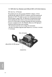
... offers max link rate up to 867Mbps. * The transmission speed may vary according to support WiFi + BT. WiFi + BT Module ASRock WiFi 2.4/5 GHz Antenna Antenna Ports 10 English BT 4.0 also includes Low Energy Technology and ensures extraordinary low power consumption for WiFi 802.11... a/b/g/n/ac connectivity standards and Bluetooth v4.0. 1.5 WiFi-802.11ac Module and ASRock WiFi 2.4/5 GHz Antenna WiFi-802.11ac + BT Module This motherboard comes with an exclusive WiFi 802.11 a/b/g/n/ac + BT v4.0 module that adds a whole new ...
... offers max link rate up to 867Mbps. * The transmission speed may vary according to support WiFi + BT. WiFi + BT Module ASRock WiFi 2.4/5 GHz Antenna Antenna Ports 10 English BT 4.0 also includes Low Energy Technology and ensures extraordinary low power consumption for WiFi 802.11... a/b/g/n/ac connectivity standards and Bluetooth v4.0. 1.5 WiFi-802.11ac Module and ASRock WiFi 2.4/5 GHz Antenna WiFi-802.11ac + BT Module This motherboard comes with an exclusive WiFi 802.11 a/b/g/n/ac + BT v4.0 module that adds a whole new ...

User Manual
Page 16
... screw hole on the bracket. Step 2 Attach the WiFi Module Bracket to attach the bracket and the WiFi card, but do not tighten the screw. X99E-ITX/ac WiFi Module and SMA Wi-Fi Antenna Cables Installation Guide Step 1 Prepare the WiFi Module, WiFi Module Bracket, and the two screws (M2*3) that holds...
... screw hole on the bracket. Step 2 Attach the WiFi Module Bracket to attach the bracket and the WiFi card, but do not tighten the screw. X99E-ITX/ac WiFi Module and SMA Wi-Fi Antenna Cables Installation Guide Step 1 Prepare the WiFi Module, WiFi Module Bracket, and the two screws (M2*3) that holds...

User Manual
Page 18
X99E-ITX/ac Step 8 Insert the RP-SMA Wi-Fi Antenna Connectors to the antenna ports on the I/O shield Step 9 Fasten the screw nuts to secure the antenna connectors. 13 English
X99E-ITX/ac Step 8 Insert the RP-SMA Wi-Fi Antenna Connectors to the antenna ports on the I/O shield Step 9 Fasten the screw nuts to secure the antenna connectors. 13 English

User Manual
Page 20
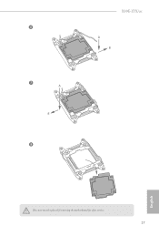
Do not force to insert the CPU into the socket, please check if the PnP cap is on the socket, if the CPU surface is unclean, or if there are any bent pins in the socket. X99E-ITX/ac 2.1 Installing the CPU 1. Otherwise, the CPU will be seriously damaged. 2. Unplug all power cables before installing the CPU. CAUTION: Please note that X99 platform is only compatible with the LGA 2011 socket (for X79 platform). 1 A B A 2 B 15 English Before you insert the 2011-3-Pin CPU into the socket if above situation is incompatible with the LGA 2011-3 socket, which is found.
Do not force to insert the CPU into the socket, please check if the PnP cap is on the socket, if the CPU surface is unclean, or if there are any bent pins in the socket. X99E-ITX/ac 2.1 Installing the CPU 1. Otherwise, the CPU will be seriously damaged. 2. Unplug all power cables before installing the CPU. CAUTION: Please note that X99 platform is only compatible with the LGA 2011 socket (for X79 platform). 1 A B A 2 B 15 English Before you insert the 2011-3-Pin CPU into the socket if above situation is incompatible with the LGA 2011-3 socket, which is found.
User Manual
Page 22
6 7 A B 8 X99E-ITX/ac A B English The cover must be placed if returning the motherboard for after service. 17
6 7 A B 8 X99E-ITX/ac A B English The cover must be placed if returning the motherboard for after service. 17
User Manual
Page 28
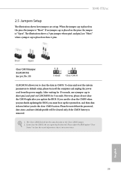
... placed on the pins, the jumper is "Short". After waiting for 5 seconds. The Clear CMOS Switch has the same function as the Clear CMOS jumper. 2. X99E-ITX/ac 2.5 Jumpers Setup The illustration shows how jumpers are "Short" when a jumper cap is placed on these 2 pins. English 23
... placed on the pins, the jumper is "Short". After waiting for 5 seconds. The Clear CMOS Switch has the same function as the Clear CMOS jumper. 2. X99E-ITX/ac 2.5 Jumpers Setup The illustration shows how jumpers are "Short" when a jumper cap is placed on these 2 pins. English 23
User Manual
Page 30
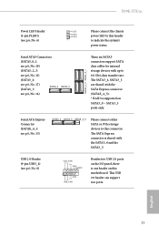
... p.6, No. 16) SATA3_2_3 SATA3_0_1 These six SATA3 connectors support SATA data cables for internal storage devices with up to 6.0 Gb/s data transfer rate. English 25 X99E-ITX/ac Power LED Header (3-pin PLED1) (see p.6, No. 6) PLEDPLED+ PLED+ 1 Please connect the chassis power LED to this header to this motherboard. The SATA3_4, SATA3_5 are...
... p.6, No. 16) SATA3_2_3 SATA3_0_1 These six SATA3 connectors support SATA data cables for internal storage devices with up to 6.0 Gb/s data transfer rate. English 25 X99E-ITX/ac Power LED Header (3-pin PLED1) (see p.6, No. 6) PLEDPLED+ PLED+ 1 Please connect the chassis power LED to this header to this motherboard. The SATA3_4, SATA3_5 are...
User Manual
Page 31
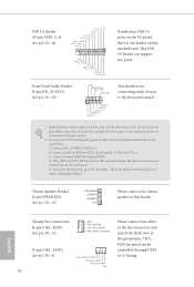
... and adjust "Recording Volume". Connect Mic_IN (MIC) to install your system. 2. Connect Ground (GND) to connect them for the AC'97 audio panel. Chassis Speaker Header (4-pin SPEAKER1) (see p.6, No. 13) GND FAN_VOLTAGE CHA_FAN_SPEED FAN_SPEED_CONTROL Please connect fan cables to... Header (9-pin HD_AUDIO1) (see p.6, No. 14) ID IntA_P_D+ IntA_P_DGND IntA_P_SSTX+ IntA_P_SSTXGND IntA_P_SSRX+ IntA_P_SSRXVbus 1 Vbus IntA_P_SSRX- If you use an AC'97 audio panel, please install it to the front audio panel. 1. C. To activate the front mic, go to function correctly. IntA_P_SSRX+ ...
... and adjust "Recording Volume". Connect Mic_IN (MIC) to install your system. 2. Connect Ground (GND) to connect them for the AC'97 audio panel. Chassis Speaker Header (4-pin SPEAKER1) (see p.6, No. 13) GND FAN_VOLTAGE CHA_FAN_SPEED FAN_SPEED_CONTROL Please connect fan cables to... Header (9-pin HD_AUDIO1) (see p.6, No. 14) ID IntA_P_D+ IntA_P_DGND IntA_P_SSTX+ IntA_P_SSTXGND IntA_P_SSRX+ IntA_P_SSRXVbus 1 Vbus IntA_P_SSRX- If you use an AC'97 audio panel, please install it to the front audio panel. 1. C. To activate the front mic, go to function correctly. IntA_P_SSRX+ ...
User Manual
Page 32
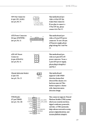
... supply, please plug it along Pin 1 and Pin 13. A TPM system also helps enhance network security, protects digital identities, and ensures platform integrity. 27 English X99E-ITX/ac CPU Fan Connector (4-pin CPU_FAN1) (see p.6, No. 2) 1 GND Signal This motherboard supports CASE OPEN detection feature that detects if the chassis cove has been removed...
... supply, please plug it along Pin 1 and Pin 13. A TPM system also helps enhance network security, protects digital identities, and ensures platform integrity. 27 English X99E-ITX/ac CPU Fan Connector (4-pin CPU_FAN1) (see p.6, No. 2) 1 GND Signal This motherboard supports CASE OPEN detection feature that detects if the chassis cove has been removed...

User Manual
Page 34
... 3 C 8cm Type 2280 English 29 The Ultra M.2 Socket (M2) can accommodate either a M.2 SATA3 6.0 Gb/s module or a M.2 PCI Express module up to replace mPCIe and mSATA. X99E-ITX/ac 2.8 M.2_SSD (NGFF) Module Installation Guide The M.2, also known as the Next Generation Form Factor (NGFF), is a small size and versatile card edge connector that aims...
... 3 C 8cm Type 2280 English 29 The Ultra M.2 Socket (M2) can accommodate either a M.2 SATA3 6.0 Gb/s module or a M.2 PCI Express module up to replace mPCIe and mSATA. X99E-ITX/ac 2.8 M.2_SSD (NGFF) Module Installation Guide The M.2, also known as the Next Generation Form Factor (NGFF), is a small size and versatile card edge connector that aims...

User Manual
Page 36
X99E-ITX/ac M.2_SSD (NGFF) Module Support List PCIe Interface SATA Interface Plextor PX-AG256M6e Plextor PX-AG512M6e SanDisk SD6PP4M-128G SanDisk SD6PP4M-256G Samsung XP941-512G (MZHPU512HCGL) Samsung SH2280S3/480G Samsung SM951 (MZHPV256HDGL) Kingston SH2280S3/480G ADATA AXNS381E-128GM-B ADATA AXNS381E-256GM-B Crucial CT120M500SSD4/120G Crucial CT240M500SSD4/240G Intel SSDSCKGW080A401/80G Kingston RBU-SNS8400S3/180GD For the latest updates of M.2_SSD (NFGG) module support list, please visit our website for details: http://www.asrock.com English 31
X99E-ITX/ac M.2_SSD (NGFF) Module Support List PCIe Interface SATA Interface Plextor PX-AG256M6e Plextor PX-AG512M6e SanDisk SD6PP4M-128G SanDisk SD6PP4M-256G Samsung XP941-512G (MZHPU512HCGL) Samsung SH2280S3/480G Samsung SM951 (MZHPV256HDGL) Kingston SH2280S3/480G ADATA AXNS381E-128GM-B ADATA AXNS381E-256GM-B Crucial CT120M500SSD4/120G Crucial CT240M500SSD4/240G Intel SSDSCKGW080A401/80G Kingston RBU-SNS8400S3/180GD For the latest updates of M.2_SSD (NFGG) module support list, please visit our website for details: http://www.asrock.com English 31
User Manual
Page 38
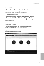
X99E-ITX/ac 3.2 A-Tuning A-Tuning is ASRock's multi purpose software suite with a new interface, more new features and improved utilities, including XFast RAM, Dehumidifier, Good Night LED, FAN-Tastic Tuning, OC Tweaker ... main menu: Operation Mode, Tools, OC Tweaker, System Info, Live Update, Tech Service and Settings. Operation Mode Choose an operation mode for your system from ASRock's support CD, A-Tuning will pop up. 3.2.2 Using A-Tuning There are six sections in -one driver to your computer. 33 English
X99E-ITX/ac 3.2 A-Tuning A-Tuning is ASRock's multi purpose software suite with a new interface, more new features and improved utilities, including XFast RAM, Dehumidifier, Good Night LED, FAN-Tastic Tuning, OC Tweaker ... main menu: Operation Mode, Tools, OC Tweaker, System Info, Live Update, Tech Service and Settings. Operation Mode Choose an operation mode for your system from ASRock's support CD, A-Tuning will pop up. 3.2.2 Using A-Tuning There are six sections in -one driver to your computer. 33 English

User Manual
Page 40
... Key and let your OC settings as hard disk model, serial number, firmware, power on count, power on , and the duration of the dehumidifying process. X99E-ITX/ac FAN-Tastic Tuning Configure up to the friends. Then you can send this function and configure the period of time until the computer powers on...
... Key and let your OC settings as hard disk model, serial number, firmware, power on count, power on , and the duration of the dehumidifying process. X99E-ITX/ac FAN-Tastic Tuning Configure up to the friends. Then you can send this function and configure the period of time until the computer powers on...
User Manual
Page 42
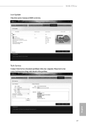
English 37 X99E-ITX/ac Tech Service Contact Tech Service if you have problems with your contact information along with details of BIOS or drivers. Please leave your computer. Live Update Check for newer versions of the problem.
English 37 X99E-ITX/ac Tech Service Contact Tech Service if you have problems with your contact information along with details of BIOS or drivers. Please leave your computer. Live Update Check for newer versions of the problem.

