User Manual
Page 6
...; Workstation 1S Xeon® processors 3500 series - ATX Form Factor: 12.0-in x 9.6-in, 30.5 cm x 24.4 cm - Intel® Socket 1366 CoreTM i7 Processor Extreme Edition / CoreTM i7 Processor Supports Intel® Dynamic Speed Technology - Northbridge: Intel® X58 - Triple Channel DDR3 Memory Technology (see CAUTION 2) - Realtek RTL8111E - Supports Wake-On-LAN -
...; Workstation 1S Xeon® processors 3500 series - ATX Form Factor: 12.0-in x 9.6-in, 30.5 cm x 24.4 cm - Intel® Socket 1366 CoreTM i7 Processor Extreme Edition / CoreTM i7 Processor Supports Intel® Dynamic Speed Technology - Northbridge: Intel® X58 - Triple Channel DDR3 Memory Technology (see CAUTION 2) - Realtek RTL8111E - Supports Wake-On-LAN -

User Manual
Page 10
...ASRock... the ASRock AIWI utility either from ASRock official website or ASRock software support ...PC games. ASRock APP Charger.... 14. Connecting your friends! ASRock website: http://www.asrock.com/Feature/Aiwi/index.asp 11...OC settings as iPhone/iPod/iPad Touch, ASRock has prepared a wonderful solution for the ... store to ASRock official website regularly, we will automatically shutdown..../iPod touch as yours! ASRock AIWI utility introduces a new...ASRock website: http://www.asrock.com/Feature/AppCharger/index.asp 12. It helps you - ASRock AIWI is no longer only available at Wii. ASRock...
...ASRock... the ASRock AIWI utility either from ASRock official website or ASRock software support ...PC games. ASRock APP Charger.... 14. Connecting your friends! ASRock website: http://www.asrock.com/Feature/Aiwi/index.asp 11...OC settings as iPhone/iPod/iPad Touch, ASRock has prepared a wonderful solution for the ... store to ASRock official website regularly, we will automatically shutdown..../iPod touch as yours! ASRock AIWI utility introduces a new...ASRock website: http://www.asrock.com/Feature/AppCharger/index.asp 12. It helps you - ASRock AIWI is no longer only available at Wii. ASRock...
User Manual
Page 12
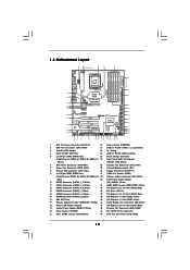
... I/O AUDIO CODEC HDMI_SPDIF1 1 HD_AUDIO1 CD1 COM1 1 1 PCI1 RoHS PCI2 1394a NEC USB 3.0 Front USB 3.0 PCIE5 FLOPPY1 IR1 1 CHA_FAN1 FRONT_1394 1 X58 Extreme6 Intel ICH10R CMOS Battery Debug LED USB8_9 1 USB3_1_2 CLRCMOS1 1 SPEAKER1 1 8Mb BIOS PWRBTN PLED1 1 PLED PWRBTN PANEL1 RSTBTN 1 HDLED RESET 7 8 ...1 ATX 12V Power Connector (ATX12V1) 22 Power Switch (PWRBTN) 2 CPU Fan Connector (CPU_FAN1) 23 USB 3.0 Header (USB3_1_2, Light Blue) 3 1366-Pin CPU Socket 24 Dr. Debug 4 North Bridge Controller 25 USB 2.0 Header (USB8_9, Blue) 5 3 x 240-pin DDR3 DIMM Slots 26...
... I/O AUDIO CODEC HDMI_SPDIF1 1 HD_AUDIO1 CD1 COM1 1 1 PCI1 RoHS PCI2 1394a NEC USB 3.0 Front USB 3.0 PCIE5 FLOPPY1 IR1 1 CHA_FAN1 FRONT_1394 1 X58 Extreme6 Intel ICH10R CMOS Battery Debug LED USB8_9 1 USB3_1_2 CLRCMOS1 1 SPEAKER1 1 8Mb BIOS PWRBTN PLED1 1 PLED PWRBTN PANEL1 RSTBTN 1 HDLED RESET 7 8 ...1 ATX 12V Power Connector (ATX12V1) 22 Power Switch (PWRBTN) 2 CPU Fan Connector (CPU_FAN1) 23 USB 3.0 Header (USB3_1_2, Light Blue) 3 1366-Pin CPU Socket 24 Dr. Debug 4 North Bridge Controller 25 USB 2.0 Header (USB8_9, Blue) 5 3 x 240-pin DDR3 DIMM Slots 26...
User Manual
Page 16
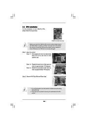
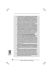
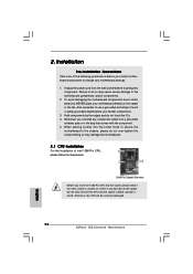
... Step 1-3. Otherwise, the CPU will be placed if returning the motherboard for after service. 16 2.3 CPU Installation For the installation of Intel 1366-Pin CPU, please follow the steps below. Remove PnP Cap (Pick and Place Cap). 1. Do not force to fully open position at approximately ...100 degrees. Load Plate Contact Array Socket Body Load Lever 1366-Pin Socket Overview Before you insert the 1366-Pin CPU into the socket if above situation is found. Step 1-2. Step 2. Rotate the load plate to insert ...
... Step 1-3. Otherwise, the CPU will be placed if returning the motherboard for after service. 16 2.3 CPU Installation For the installation of Intel 1366-Pin CPU, please follow the steps below. Remove PnP Cap (Pick and Place Cap). 1. Do not force to fully open position at approximately ...100 degrees. Load Plate Contact Array Socket Body Load Lever 1366-Pin Socket Overview Before you insert the 1366-Pin CPU into the socket if above situation is found. Step 1-2. Step 2. Rotate the load plate to insert ...

User Manual
Page 17
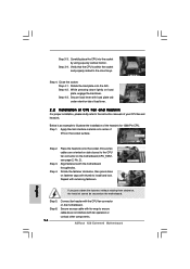
Orient the CPU with black lines. orientation key notch Pin1 Pin1 alignment key orientation key notch 1366-Pin CPU alignment key 1366-Pin Socket For proper inserting, please ensure to the orient keys. Rotate the load plate onto the IHS. Carefully place the...black line black line Step 3. Hold the CPU by using a purely vertical motion. Locate Pin1 and the two orientation key notches. Step 4-2. Step 4-3. Insert the 1366-Pin CPU: Step 3-1. Step 3-4. Secure load lever with the two alignment keys of load lever. 17 Step 3-2. Step 3-3. Step 4. Close the socket: Step...
Orient the CPU with black lines. orientation key notch Pin1 Pin1 alignment key orientation key notch 1366-Pin CPU alignment key 1366-Pin Socket For proper inserting, please ensure to the orient keys. Rotate the load plate onto the IHS. Carefully place the...black line black line Step 3. Hold the CPU by using a purely vertical motion. Locate Pin1 and the two orientation key notches. Step 4-2. Step 4-3. Insert the 1366-Pin CPU: Step 3-1. Step 3-4. Secure load lever with the two alignment keys of load lever. 17 Step 3-2. Step 3-3. Step 4. Close the socket: Step...
User Manual
Page 18
...need to spray thermal interface material between the CPU and the heatsink to improve heat dissipation. Step 4. Step 5. Step 6. Connect fan header with Intel 1366-Pin CPU to dissipate heat. Place the heatsink onto the socket. Step 1. Please be secured on the motherboard (CPU_FAN1, see page 12, No. ... fan compliant with the CPU fan connector on the socket surface. Ensure fan cables are securely fastened and in good contact with 1366-Pin socket that the CPU and the heatsink are oriented on side closest to the CPU fan connector on the motherboard. Please ...
...need to spray thermal interface material between the CPU and the heatsink to improve heat dissipation. Step 4. Step 5. Step 6. Connect fan header with Intel 1366-Pin CPU to dissipate heat. Place the heatsink onto the socket. Step 1. Please be secured on the motherboard (CPU_FAN1, see page 12, No. ... fan compliant with the CPU fan connector on the socket surface. Ensure fan cables are securely fastened and in good contact with 1366-Pin socket that the CPU and the heatsink are oriented on side closest to the CPU fan connector on the motherboard. Please ...
Quick Installation Guide
Page 2
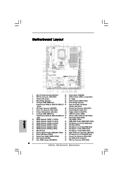
... / XFIRE Power Connector 21 Clear CMOS Jumper (CLRCMOS1) 44 CPU Fan Connector (CPU_FAN2) 2 ASRock X58 Extreme6 Motherboard English Motherboard Layout 1 ATX 12V Power Connector (ATX12V1) 22 Power Switch (PWRBTN) 2 CPU Fan Connector (CPU_FAN1) 23 USB 3.0 Header (USB3_1_2, Light Blue) 3 1366-Pin CPU Socket 24 Dr. Debug 4 North Bridge Controller 25 USB 2.0 Header (USB8_9, Blue...
... / XFIRE Power Connector 21 Clear CMOS Jumper (CLRCMOS1) 44 CPU Fan Connector (CPU_FAN2) 2 ASRock X58 Extreme6 Motherboard English Motherboard Layout 1 ATX 12V Power Connector (ATX12V1) 22 Power Switch (PWRBTN) 2 CPU Fan Connector (CPU_FAN1) 23 USB 3.0 Header (USB3_1_2, Light Blue) 3 1366-Pin CPU Socket 24 Dr. Debug 4 North Bridge Controller 25 USB 2.0 Header (USB8_9, Blue...
Quick Installation Guide
Page 6
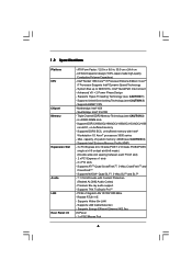
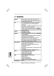
Intel® Socket 1366 CoreTM i7 Processor Extreme Edition / CoreTM i7 Processor Supports Intel® Dynamic Speed Technology - Supports Untied Overclocking Technology (see CAUTION 4) - Northbridge: Intel® X58 - Supports THX TruStudio ProTM - Supports EM64T CPU - Southbridge...Workstation 1S Xeon® processors 3500 series - 1.2 Specifications Platform CPU Chipset Memory Expansion Slot Audio LAN Rear Panel I /O Panel 6 ASRock X58 Extreme6 Motherboard English ATX Form Factor: 12.0-in x 9.6-in, 30.5 cm x 24.4 cm - Intel® QuickPath Interconnect - Max....
Intel® Socket 1366 CoreTM i7 Processor Extreme Edition / CoreTM i7 Processor Supports Intel® Dynamic Speed Technology - Supports Untied Overclocking Technology (see CAUTION 4) - Northbridge: Intel® X58 - Supports THX TruStudio ProTM - Supports EM64T CPU - Southbridge...Workstation 1S Xeon® processors 3500 series - 1.2 Specifications Platform CPU Chipset Memory Expansion Slot Audio LAN Rear Panel I /O Panel 6 ASRock X58 Extreme6 Motherboard English ATX Form Factor: 12.0-in x 9.6-in, 30.5 cm x 24.4 cm - Intel® QuickPath Interconnect - Max....
Quick Installation Guide
Page 10
...first utility to record the OC settings and share with your iPhone/iPod touch. Your friends then can only be used. 10 ASRock X58 Extreme6 Motherboard English ASRock website: http://www.asrock.com/Feature/Aiwi/index.asp 11. Please be noticed that the OC profile can load the OC profile to their own system... then you the most up-do not forget to pay attention to adopt two different CPU cooler types, Socket LGA 775 and LGA 1366. ASRock APP Charger. ASRock AIWI utility introduces a new way of overclocking settings. Connecting your Apple devices, such as yours!
...first utility to record the OC settings and share with your iPhone/iPod touch. Your friends then can only be used. 10 ASRock X58 Extreme6 Motherboard English ASRock website: http://www.asrock.com/Feature/Aiwi/index.asp 11. Please be noticed that the OC profile can load the OC profile to their own system... then you the most up-do not forget to pay attention to adopt two different CPU cooler types, Socket LGA 775 and LGA 1366. ASRock APP Charger. ASRock AIWI utility introduces a new way of overclocking settings. Connecting your Apple devices, such as yours!
Quick Installation Guide
Page 12
.... Whenever you insert the 1366-Pin CPU into the socket, please check if the CPU surface is unclean or if there is found. Doing so may cause severe damage to the chassis, please do not touch the ICs. 4. Otherwise, the CPU will be seriously damaged. 12 ASRock X58 Extreme6 Motherboard English When placing screws...
.... Whenever you insert the 1366-Pin CPU into the socket, please check if the CPU surface is unclean or if there is found. Doing so may cause severe damage to the chassis, please do not touch the ICs. 4. Otherwise, the CPU will be seriously damaged. 12 ASRock X58 Extreme6 Motherboard English When placing screws...

Quick Installation Guide
Page 13
... the CPU with the two alignment keys of the socket. 13 ASRock X58 Extreme6 Motherboard English Remove PnP Cap (Pick and Place Cap). Insert the 1366-Pin CPU: Step 3-1. orientation key notch Pin1 Pin1 alignment key orientation key notch 1366-Pin CPU alignment key 1366-Pin Socket For proper inserting, please ensure to clear retention tab...
... the CPU with the two alignment keys of the socket. 13 ASRock X58 Extreme6 Motherboard English Remove PnP Cap (Pick and Place Cap). Insert the 1366-Pin CPU: Step 3-1. orientation key notch Pin1 Pin1 alignment key orientation key notch 1366-Pin CPU alignment key 1366-Pin Socket For proper inserting, please ensure to clear retention tab...
Quick Installation Guide
Page 14
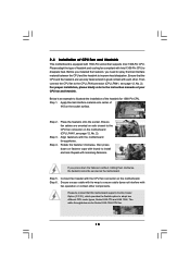
... motherboard. Secure excess cable with fan operation or contact other components. Close the socket: Step 4-1. Apply thermal interface material onto center of the heatsink for 1366-Pin CPU. Step 3-3. Secure load lever with load plate tab under retention tab of load lever. 2.2 Installation of CPU Fan and Heatsink For proper installation... oriented on side closest to illustrate the installation of IHS on the motherboard. Carefully place the CPU into the socket by using a purely vertical motion. ASRock X58 Extreme6 Motherboard
... motherboard. Secure excess cable with fan operation or contact other components. Close the socket: Step 4-1. Apply thermal interface material onto center of the heatsink for 1366-Pin CPU. Step 3-3. Secure load lever with load plate tab under retention tab of load lever. 2.2 Installation of CPU Fan and Heatsink For proper installation... oriented on side closest to illustrate the installation of IHS on the motherboard. Carefully place the CPU into the socket by using a purely vertical motion. ASRock X58 Extreme6 Motherboard

Quick Installation Guide
Page 15
Please be noticed that this motherboard supports Combo Cooler Option (C.C.O.), which provides the flexible option to adopt two different CPU cooler types, Socket LGA 775 and LGA 1366. The white throughholes are for Socket LGA 1366 CPU fan. 15 ASRock X58 Extreme6 Motherboard English
Please be noticed that this motherboard supports Combo Cooler Option (C.C.O.), which provides the flexible option to adopt two different CPU cooler types, Socket LGA 775 and LGA 1366. The white throughholes are for Socket LGA 1366 CPU fan. 15 ASRock X58 Extreme6 Motherboard English

Quick Installation Guide
Page 155
ASRock X58 Extreme6 Motherboard 155 , Intel 1366. ! . 1. 1-1. 1366. . : 1366- .
ASRock X58 Extreme6 Motherboard 155 , Intel 1366. ! . 1. 1-1. 1366. . : 1366- .

Quick Installation Guide
Page 156
Cap). 135 . 100 . PnP (Pick and Place PnP 3 156 1366- 3-3 3-4 1366. ASRock X58 Extreme6 Motherboard 1-2. 1-3. 2.
Cap). 135 . 100 . PnP (Pick and Place PnP 3 156 1366- 3-3 3-4 1366. ASRock X58 Extreme6 Motherboard 1-2. 1-3. 2.