
User Manual
Page 2
...undesired operation. In no responsibility for any interference received, including interference that may not be constructed as a commitment by ASRock. CALIFORNIA, USA ONLY The Lithium battery adopted on this manual are used only for informational use only and subject to...may or may appear in this manual. Disclaimer: Specifications and information contained in this motherboard contains Perchlorate, a toxic substance controlled in the manual or product. ASRock assumes no event shall ASRock, its directors, officers, employees, or agents be reproduced, transcribed, transmitted, or...
...undesired operation. In no responsibility for any interference received, including interference that may not be constructed as a commitment by ASRock. CALIFORNIA, USA ONLY The Lithium battery adopted on this manual are used only for informational use only and subject to...may or may appear in this manual. Disclaimer: Specifications and information contained in this motherboard contains Perchlorate, a toxic substance controlled in the manual or product. ASRock assumes no event shall ASRock, its directors, officers, employees, or agents be reproduced, transcribed, transmitted, or...
User Manual
Page 3
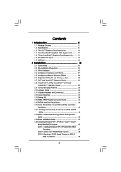
... 1 Introduction 5 1.1 Package Contents 5 1.2 Specifications 6 1.3 Two SLITM Graphics Card Support List 10 1.4 Two CrossFireXTM Graphics Card Support List 11 1.5 Three CrossFireXTM Graphics Card Support List .......... 11 1.6 Motherboard Layout 12 1.7 I/O Panel 13 2 Installation 14 2.1 Screw Holes 14 2.2 Pre-installation Precautions 14 2.3 CPU Installation 15 2.4 Installation of Heatsink and CPU fan 17 2.5 Installation of...
... 1 Introduction 5 1.1 Package Contents 5 1.2 Specifications 6 1.3 Two SLITM Graphics Card Support List 10 1.4 Two CrossFireXTM Graphics Card Support List 11 1.5 Three CrossFireXTM Graphics Card Support List .......... 11 1.6 Motherboard Layout 12 1.7 I/O Panel 13 2 Installation 14 2.1 Screw Holes 14 2.2 Pre-installation Precautions 14 2.3 CPU Installation 15 2.4 Installation of Heatsink and CPU fan 17 2.5 Installation of...
User Manual
Page 5
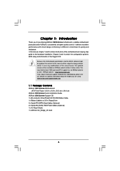
... related to quality and endurance. www.asrock.com/support/index.asp 1.1 Package Contents ASRock X58 Extreme Motherboard (ATX Form Factor: 12.0-in x 9.6-in, 30.5 cm x 24.4 cm) ASRock X58 Extreme Quick Installation Guide ASRock X58 Extreme Support CD 1 x 80-conductor Ultra ATA 66/100/133 IDE Ribbon Cable 1 x Ribbon Cable for purchasing ASRock X58 Extreme motherboard, a reliable motherboard produced under ASRock's consistently stringent quality control. Because the...
... related to quality and endurance. www.asrock.com/support/index.asp 1.1 Package Contents ASRock X58 Extreme Motherboard (ATX Form Factor: 12.0-in x 9.6-in, 30.5 cm x 24.4 cm) ASRock X58 Extreme Quick Installation Guide ASRock X58 Extreme Support CD 1 x 80-conductor Ultra ATA 66/100/133 IDE Ribbon Cable 1 x Ribbon Cable for purchasing ASRock X58 Extreme motherboard, a reliable motherboard produced under ASRock's consistently stringent quality control. Because the...
User Manual
Page 8
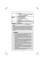
...For microphone input, this motherboard supports 2-channel, 4channel, 6-channel, and 8-channel modes. ASRock U-COP (see CAUTION 11) - CPU Temperature Sensing Monitor - Voltage Monitoring: +12V, +5V, +3.3V, CPU Vcore OS - We are not responsible for proper connection. 6. This motherboard supports Untied Overclocking Technology...make sure to the components and devices of "Hyper Threading Technology", please check page 61. 2. For audio output, this motherboard supports both stereo and mono modes. CPU Quiet Fan - Be- Before installing SATAII hard disk to SATAII connector, please...
...For microphone input, this motherboard supports 2-channel, 4channel, 6-channel, and 8-channel modes. ASRock U-COP (see CAUTION 11) - CPU Temperature Sensing Monitor - Voltage Monitoring: +12V, +5V, +3.3V, CPU Vcore OS - We are not responsible for proper connection. 6. This motherboard supports Untied Overclocking Technology...make sure to the components and devices of "Hyper Threading Technology", please check page 61. 2. For audio output, this motherboard supports both stereo and mono modes. CPU Quiet Fan - Be- Before installing SATAII hard disk to SATAII connector, please...
User Manual
Page 9
...to your USB flash drive, floppy disk or hard drive, then you resume the system, please check if the CPU fan on the motherboard functions properly and unplug the power cord, then plug it is not recommended to spray thermal grease between the CPU and the heatsink ...is a user-friendly ASRock overclocking tool which allows you to get the best system performance under Windows® environment. 8. This convenient BIOS update tool allows you to surveil your system by hardware monitor function and overclock your BIOS only in Flash ROM. With this motherboard offers stepless control, it...
...to your USB flash drive, floppy disk or hard drive, then you resume the system, please check if the CPU fan on the motherboard functions properly and unplug the power cord, then plug it is not recommended to spray thermal grease between the CPU and the heatsink ...is a user-friendly ASRock overclocking tool which allows you to get the best system performance under Windows® environment. 8. This convenient BIOS update tool allows you to surveil your system by hardware monitor function and overclock your BIOS only in Flash ROM. With this motherboard offers stepless control, it...
User Manual
Page 12
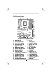
... Connector: CD1 (Black) 18 South Bridge Controller 41 Front Panel Audio Header 19 Chassis Speaker Header (SPEAKER 1, Purple) (HD_AUDIO1, Lime) 12 1.6 Motherboard Layout 123 45 6 7 24.4cm (9.6 in) PS2 Mouse PS2 Keyboard Clr CMOS 1 PS2_USB_PWR1 ATX12V1 PWR_FAN1 CHA_FAN2 8 CPU_FAN1 30.5cm (12.0 in...38 PCI Express 2.0 CrossFireX QPI 6.4GT/s 37 36 AUDIO CODEC PCIE2 PCIE3 RoHS 14 1394a VIA VT6330 SATAII_5_6 SATAII_3_4 SATAII_1_2 35 PCI1 X58 Extreme 8Mb BIOS 34 PCIE4 IDE1 15 33 32 31 Super I/O 1 IR1 FLOPPY1 HDMI_SPDIF1 1 PCI2 PCIE5 COM1 1 1 TPM1 CMOS Battery...
... Connector: CD1 (Black) 18 South Bridge Controller 41 Front Panel Audio Header 19 Chassis Speaker Header (SPEAKER 1, Purple) (HD_AUDIO1, Lime) 12 1.6 Motherboard Layout 123 45 6 7 24.4cm (9.6 in) PS2 Mouse PS2 Keyboard Clr CMOS 1 PS2_USB_PWR1 ATX12V1 PWR_FAN1 CHA_FAN2 8 CPU_FAN1 30.5cm (12.0 in...38 PCI Express 2.0 CrossFireX QPI 6.4GT/s 37 36 AUDIO CODEC PCIE2 PCIE3 RoHS 14 1394a VIA VT6330 SATAII_5_6 SATAII_3_4 SATAII_1_2 35 PCI1 X58 Extreme 8Mb BIOS 34 PCIE4 IDE1 15 33 32 31 Super I/O 1 IR1 FLOPPY1 HDMI_SPDIF1 1 PCI2 PCIE5 COM1 1 1 TPM1 CMOS Battery...
User Manual
Page 14
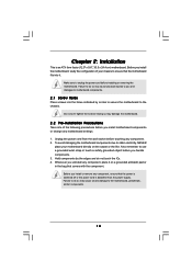
...2.1 Screw Holes Place screws into the holes indicated by the edges and do so may damage the motherboard. 2.2 Pre-installation Precautions Take note of your motherboard directly on a grounded antistatic pad or in the bag that comes with the component. Chapter 2: Installation... This is detached from the wall socket before installing or removing the motherboard. To avoid damaging the motherboard components due to static electricity, NEVER place your chassis to you install motherboard components or change any component. 2. Before you handle components. 3. Failure to ...
...2.1 Screw Holes Place screws into the holes indicated by the edges and do so may damage the motherboard. 2.2 Pre-installation Precautions Take note of your motherboard directly on a grounded antistatic pad or in the bag that comes with the component. Chapter 2: Installation... This is detached from the wall socket before installing or removing the motherboard. To avoid damaging the motherboard components due to static electricity, NEVER place your chassis to you install motherboard components or change any component. 2. Before you handle components. 3. Failure to ...
User Manual
Page 15
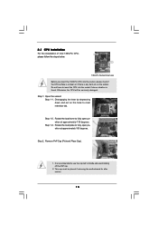
... depressing down and out on the socket. Step 1-2. Step 2. Remove PnP Cap (Pick and Place Cap). 1. Otherwise, the CPU will be placed if returning the motherboard for after service. 15 Step 1. Step 1-3. It is any bent pin on the hook to handle and avoid kicking off the PnP cap. 2. Rotate the...
... depressing down and out on the socket. Step 1-2. Step 2. Remove PnP Cap (Pick and Place Cap). 1. Otherwise, the CPU will be placed if returning the motherboard for after service. 15 Step 1. Step 1-3. It is any bent pin on the hook to handle and avoid kicking off the PnP cap. 2. Rotate the...
User Manual
Page 17
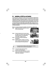
...Intel 1366-Pin CPU to the CPU_FAN connector (CPU_FAN1, see page 12, No. 2). Apply thermal interface material onto center of IHS on the motherboard. Step 3. Before you installed the heatsink, you press down on side closest to MB header fan cables are securely fastened and in good ... fan header with 1366-Pin socket that the CPU and the heatsink are oriented on side closest to the CPU fan connector on the motherboard. Press Down (4 Places) If you need to spray thermal interface material between the CPU and the heatsink to improve heat dissipation. Align...
...Intel 1366-Pin CPU to the CPU_FAN connector (CPU_FAN1, see page 12, No. 2). Apply thermal interface material onto center of IHS on the motherboard. Step 3. Before you installed the heatsink, you press down on side closest to MB header fan cables are securely fastened and in good ... fan header with 1366-Pin socket that the CPU and the heatsink are oriented on side closest to the CPU fan connector on the motherboard. Press Down (4 Places) If you need to spray thermal interface material between the CPU and the heatsink to improve heat dissipation. Align...
User Manual
Page 18
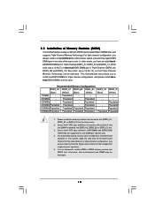
...supports Triple Channel Memory Technology. Any excess memory from the higher-sized channel is then mapped for the first priority. 2. otherwise, this motherboard and DIMM may install varying memory sizes in Channel A, Channel B and Channel C. Blue slots; Populated - Populated - Due to ...Populated - Populated 5 DIMMs Populated Populated Populated Populated - see p.12 No.7), or identical DDR3 DIMM pair in all six slots. This motherboard also allows you have to install six DDR3 DIMMs for one DIMM is not allowed to Intel® CPU spec definition, XMP DIMMs and...
...supports Triple Channel Memory Technology. Any excess memory from the higher-sized channel is then mapped for the first priority. 2. otherwise, this motherboard and DIMM may install varying memory sizes in Channel A, Channel B and Channel C. Blue slots; Populated - Populated - Due to ...Populated - Populated 5 DIMMs Populated Populated Populated Populated - see p.12 No.7), or identical DDR3 DIMM pair in all six slots. This motherboard also allows you have to install six DDR3 DIMMs for one DIMM is not allowed to Intel® CPU spec definition, XMP DIMMs and...
User Manual
Page 19
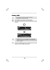
.... Align a DIMM on the slot such that the notch on the DIMM matches the break on the slot. Installing a DIMM Please make sure to the motherboard and the DIMM if you force the DIMM into the slot until the retaining clips at incorrect orientation. Firmly insert the DIMM into the slot...
.... Align a DIMM on the slot such that the notch on the DIMM matches the break on the slot. Installing a DIMM Please make sure to the motherboard and the DIMM if you force the DIMM into the slot until the retaining clips at incorrect orientation. Firmly insert the DIMM into the slot...
User Manual
Page 20
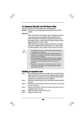
... CrossFireXTM function. 1. In single VGA card mode, it is unplugged. Installing an expansion card Step 1. Remove the system unit cover (if your motherboard is completely seated on the slot. Step 4. PCIE2 / PCIE4 (PCIE x16 slot; Keep the screws for PCI Express x1 lane width cards, such...used to the chassis with the slot and press firmly until the card is already installed in a chassis). Please connect a chassis fan to motherboard chassis fan connector (CHA_FAN1 or CHA_FAN2) when using multiple graphics cards for the card before you intend to install a PCI Express x16 graphics card...
... CrossFireXTM function. 1. In single VGA card mode, it is unplugged. Installing an expansion card Step 1. Remove the system unit cover (if your motherboard is completely seated on the slot. Step 4. PCIE2 / PCIE4 (PCIE x16 slot; Keep the screws for PCI Express x1 lane width cards, such...used to the chassis with the slot and press firmly until the card is already installed in a chassis). Please connect a chassis fan to motherboard chassis fan connector (CHA_FAN1 or CHA_FAN2) when using multiple graphics cards for the card before you intend to install a PCI Express x16 graphics card...
User Manual
Page 21
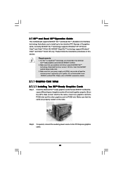
....20 or later from NVIDIA® website (www.nvidia.com). 3. Please refer to use NVIDIA® certified PSU. 2.7 SLITM and Quad SLITM Operation Guide This motherboard supports NVIDIA® SLITM and Quad SLITM (Scalable Link Interface) technology that your system. Currently, NVIDIA® SLITM technology supports Windows® XP, XP 64...
....20 or later from NVIDIA® website (www.nvidia.com). 3. Please refer to use NVIDIA® certified PSU. 2.7 SLITM and Quad SLITM Operation Guide This motherboard supports NVIDIA® SLITM and Quad SLITM (Scalable Link Interface) technology that your system. Currently, NVIDIA® SLITM technology supports Windows® XP, XP 64...
User Manual
Page 25
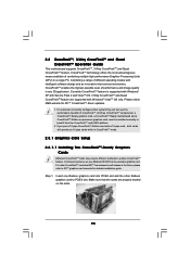
...graphics card to benefit from the CrossFireXTM multi-GPU platform. 2. Step 1. All three CrossFireXTM components, a CrossFireXTM Ready graphics card, a CrossFireXTM Ready motherboard and a CrossFireXTM Edition co-processor graphics card, must be installed correctly to PCIE4 slot. If you pair a 12-pipe CrossFireXTM Edition card with ... incorrectly configures their system they will operate as the example graphics card. 2.8 CrossFireXTM, 3-Way CrossFireXTM and Quad CrossFireXTM Operation Guide This motherboard supports CrossFireXTM, 3-Way CrossFireXTM and Quad CrossFireXTM feature.
...graphics card to benefit from the CrossFireXTM multi-GPU platform. 2. Step 1. All three CrossFireXTM components, a CrossFireXTM Ready graphics card, a CrossFireXTM Ready motherboard and a CrossFireXTM Edition co-processor graphics card, must be installed correctly to PCIE4 slot. If you pair a 12-pipe CrossFireXTM Edition card with ... incorrectly configures their system they will operate as the example graphics card. 2.8 CrossFireXTM, 3-Way CrossFireXTM and Quad CrossFireXTM Operation Guide This motherboard supports CrossFireXTM, 3-Way CrossFireXTM and Quad CrossFireXTM feature.
User Manual
Page 26
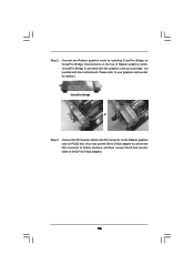
... the Radeon graphics card on the top of Radeon graphics cards. (CrossFire Bridge is provided with the graphics card you purchase, not bundled with this motherboard.
... the Radeon graphics card on the top of Radeon graphics cards. (CrossFire Bridge is provided with the graphics card you purchase, not bundled with this motherboard.
User Manual
Page 27
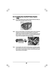
... cable to connect Radeon graphics cards on PCIE4 and PCIE5 slots. (CrossFire Bridge is provided with the graphics card you purchase, not bundled with this motherboard. 2.8.1.2 Installing Three CrossFireXTM-Ready Graphics Cards Step 1. Step 2. Use one CrossFire Bridge to connect Radeon graphics cards on PCIE2 and PCIE4 slots, and use the...
... cable to connect Radeon graphics cards on PCIE4 and PCIE5 slots. (CrossFire Bridge is provided with the graphics card you purchase, not bundled with this motherboard. 2.8.1.2 Installing Three CrossFireXTM-Ready Graphics Cards Step 1. Step 2. Use one CrossFire Bridge to connect Radeon graphics cards on PCIE2 and PCIE4 slots, and use the...
User Manual
Page 30
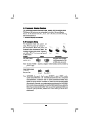
... updating the BIOS, you to default setup, please turn off the computer and unplug the power cord from the power supply. 2.9 Surround Display Feature This motherboard supports Surround Display upgrade. Note: To select +5VSB, it down before you need to short pin2 and pin3 on PCI Express VGA cards, you update...
... updating the BIOS, you to default setup, please turn off the computer and unplug the power cord from the power supply. 2.9 Surround Display Feature This motherboard supports Surround Display upgrade. Note: To select +5VSB, it down before you need to short pin2 and pin3 on PCI Express VGA cards, you update...
User Manual
Page 31
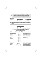
... ATAII Connectors (SATAII_1_2: see p.12, No. 15) (SATAII_3_4: see p.12, No. 16) (SATAII_5_6: see p.12 No. 14) PIN1 IDE1 connect the blue end to the motherboard connect the black end to the IDE devices 80-conductor ATA 66/100/133 cable Note: Please refer to Pin1 Note: Make sure the red...-striped side of the cable is plugged into Pin1 side of the motherboard! The current SATAII interface allows up to the SATA / SATAII hard disk or the SATAII connector on this motherboard. 31 Placing jumper caps over these headers and connectors. Do NOT place jumper caps over the...
... ATAII Connectors (SATAII_1_2: see p.12, No. 15) (SATAII_3_4: see p.12, No. 16) (SATAII_5_6: see p.12 No. 14) PIN1 IDE1 connect the blue end to the motherboard connect the black end to the IDE devices 80-conductor ATA 66/100/133 cable Note: Please refer to Pin1 Note: Make sure the red...-striped side of the cable is plugged into Pin1 side of the motherboard! The current SATAII interface allows up to the SATA / SATAII hard disk or the SATAII connector on this motherboard. 31 Placing jumper caps over these headers and connectors. Do NOT place jumper caps over the...
User Manual
Page 32
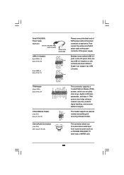
... store keys, digital certificates, passwords, and data. This connector allows you to the power connector of SATA power cable to the power connector on this motherboard. This connector supports a Trusted Platform Module (TPM) system, which can support two USB 2.0 ports. Serial ATA (SATA) Power Cable (Optional) connect to the SATA HDD...
... store keys, digital certificates, passwords, and data. This connector allows you to the power connector of SATA power cable to the power connector on this motherboard. This connector supports a Trusted Platform Module (TPM) system, which can support two USB 2.0 ports. Serial ATA (SATA) Power Cable (Optional) connect to the SATA HDD...
User Manual
Page 34
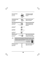
If you plan to connect the 3-Pin CPU fan to the CPU fan connector on this motherboard provides 4-Pin CPU fan (Quiet Fan) support, the 3-Pin CPU fan still can work successfully even without the fan speed control function. Chassis Speaker ... Installation ATX Power Connector (24-pin ATXPWR1) (see p.12 No. 19) 1 SPEAKER DUMMY DUMMY +5V Please connect the chassis speaker to this header. Though this motherboard, please connect it to Pin 1-3. Chassis, NB and Power Fan Connectors (4-pin CHA_FAN1) (see p.12 No. 23) FAN_SPEED_CONTROL GND +12V CHA_FAN_SPEED (3-pin CHA_FAN2) (see ...
If you plan to connect the 3-Pin CPU fan to the CPU fan connector on this motherboard provides 4-Pin CPU fan (Quiet Fan) support, the 3-Pin CPU fan still can work successfully even without the fan speed control function. Chassis Speaker ... Installation ATX Power Connector (24-pin ATXPWR1) (see p.12 No. 19) 1 SPEAKER DUMMY DUMMY +5V Please connect the chassis speaker to this header. Though this motherboard, please connect it to Pin 1-3. Chassis, NB and Power Fan Connectors (4-pin CHA_FAN1) (see p.12 No. 23) FAN_SPEED_CONTROL GND +12V CHA_FAN_SPEED (3-pin CHA_FAN2) (see ...


