
User Manual
Page 2
... may not cause harmful interference, and (2) this device must accept any errors or omissions that may apply, see www.dtsc.ca.gov/hazardouswaste/ perchlorate" ASRock Website: http://www.asrock.com Disclaimer: Specifications and information contained in this motherboard contains Perchlorate, a toxic substance controlled in any form or by any means, except duplication of...
... may not cause harmful interference, and (2) this device must accept any errors or omissions that may apply, see www.dtsc.ca.gov/hazardouswaste/ perchlorate" ASRock Website: http://www.asrock.com Disclaimer: Specifications and information contained in this motherboard contains Perchlorate, a toxic substance controlled in any form or by any means, except duplication of...

User Manual
Page 4
Contents Chapter 1 Introduction 1 1.1 Package Contents 1 1.2 Specifications 2 1.3 Motherboard Layout 7 1.4 I/O Panel 9 Chapter 2 Installation 10 2.1 Installing the CPU 11 2.2 Installing the CPU Fan and Heatsink 13 2.3 Installing Memory Modules (DIMM) 21 2.4 Expansion Slots (PCI Express ... 2.10 M.2 WiFi/BT Module Installation Guide (M2_2) 39 2.11 M.2_SSD (NGFF) Module Installation Guide (M2_3) 41 Chapter 3 Software and Utilities Operation 44 3.1 Installing Drivers 44 3.2 Phantom Gaming Tuning 45
Contents Chapter 1 Introduction 1 1.1 Package Contents 1 1.2 Specifications 2 1.3 Motherboard Layout 7 1.4 I/O Panel 9 Chapter 2 Installation 10 2.1 Installing the CPU 11 2.2 Installing the CPU Fan and Heatsink 13 2.3 Installing Memory Modules (DIMM) 21 2.4 Expansion Slots (PCI Express ... 2.10 M.2 WiFi/BT Module Installation Guide (M2_2) 39 2.11 M.2_SSD (NGFF) Module Installation Guide (M2_3) 41 Chapter 3 Software and Utilities Operation 44 3.1 Installing Drivers 44 3.2 Phantom Gaming Tuning 45
User Manual
Page 7
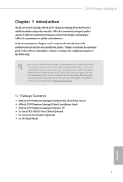
... (Optional) • 1 x I/O Panel Shield 1 English If you require technical support related to quality and endurance. ASRock website http://www.asrock.com. 1.1 Package Contents • ASRock X570 Phantom Gaming 4S Motherboard (ATX Form Factor) • ASRock X570 Phantom Gaming 4S Quick Installation Guide • ASRock X570 Phantom Gaming 4S Support CD • 2 x Serial ATA (SATA) Data Cables (Optional) • 3 x Screws for purchasing ASRock X570 Phantom Gaming 4S motherboard, a reliable motherboard produced under ASRock's consistently stringent quality control.
... (Optional) • 1 x I/O Panel Shield 1 English If you require technical support related to quality and endurance. ASRock website http://www.asrock.com. 1.1 Package Contents • ASRock X570 Phantom Gaming 4S Motherboard (ATX Form Factor) • ASRock X570 Phantom Gaming 4S Quick Installation Guide • ASRock X570 Phantom Gaming 4S Support CD • 2 x Serial ATA (SATA) Data Cables (Optional) • 3 x Screws for purchasing ASRock X570 Phantom Gaming 4S motherboard, a reliable motherboard produced under ASRock's consistently stringent quality control.
User Manual
Page 13
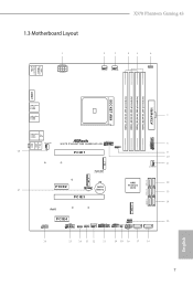
1.3 Motherboard Layout X570 Phantom Gaming 4S ATX12V1 CPU_FAN1 CPU_FAN2/WP 1 RGB_LED2 PS2 Keyboard /Mouse USB 3.2 Gen1 T: USB1 B: USB2 HDMI1 DDR4_A1 (64 bit, 288-pin module) DDR4_A2 (64 ...LINE IN Center: FRONT Bottom: MIC IN USB 3.2 Gen1 Top: T: USB7 RJ-45 B: USB8 CHA_FAN3/WP SPI_TPM_J1 X570 PHANTOM GAMING 4S 1 PCIE1 1 USB_1 USB3_9_10 1 CHA_FAN1/WP M2_2 M2_1 SATA3_5_6 SATA3_7_8 PCIE2 1 TB1 PCIE3 CMOS Battery AMD Premium X570 SATA3_1_2 M2_3 RoHS HD_AUDIO1 1 PCIE4 COM1 1 1 RGB_LED1 CHA_FAN2/WP ADDR_LED1 1 1 USB3_11_12 SPK_PLED1 USB_2_3 CLRCMOS1 1 PLED PWRBTN...
1.3 Motherboard Layout X570 Phantom Gaming 4S ATX12V1 CPU_FAN1 CPU_FAN2/WP 1 RGB_LED2 PS2 Keyboard /Mouse USB 3.2 Gen1 T: USB1 B: USB2 HDMI1 DDR4_A1 (64 bit, 288-pin module) DDR4_A2 (64 ...LINE IN Center: FRONT Bottom: MIC IN USB 3.2 Gen1 Top: T: USB7 RJ-45 B: USB8 CHA_FAN3/WP SPI_TPM_J1 X570 PHANTOM GAMING 4S 1 PCIE1 1 USB_1 USB3_9_10 1 CHA_FAN1/WP M2_2 M2_1 SATA3_5_6 SATA3_7_8 PCIE2 1 TB1 PCIE3 CMOS Battery AMD Premium X570 SATA3_1_2 M2_3 RoHS HD_AUDIO1 1 PCIE4 COM1 1 1 RGB_LED1 CHA_FAN2/WP ADDR_LED1 1 1 USB3_11_12 SPK_PLED1 USB_2_3 CLRCMOS1 1 PLED PWRBTN...

User Manual
Page 16
... grounded wrist strap or touch a safety grounded object before you and damages to motherboard components. • In order to avoid damage from static electricity to the motherboard's components, NEVER place your motherboard directly on a grounded anti-static pad or in the bag that comes with the... • When placing screws to secure the motherboard to unplug the power cord before installing or removing the motherboard. Doing so may cause physical injuries to ensure that the motherboard fits into it. Before you uninstall any motherboard settings. • Make sure to the chassis...
... grounded wrist strap or touch a safety grounded object before you and damages to motherboard components. • In order to avoid damage from static electricity to the motherboard's components, NEVER place your motherboard directly on a grounded anti-static pad or in the bag that comes with the... • When placing screws to secure the motherboard to unplug the power cord before installing or removing the motherboard. Doing so may cause physical injuries to ensure that the motherboard fits into it. Before you uninstall any motherboard settings. • Make sure to the chassis...

User Manual
Page 19
Installing the CPU Box Cooler SR1 1 2 13 English Make sure that the CPU and the heatsink are securely fastened and in good contact with each other. Please turn off the power or remove the power cord before changing a CPU or heatsink. X570 Phantom Gaming 4S 2.2 Installing the CPU Fan and Heatsink After you install the CPU into this motherboard, it is necessary to install a larger heatsink and cooling fan to improve heat dissipation. You also need to spray thermal grease between the CPU and the heatsink to dissipate heat.
Installing the CPU Box Cooler SR1 1 2 13 English Make sure that the CPU and the heatsink are securely fastened and in good contact with each other. Please turn off the power or remove the power cord before changing a CPU or heatsink. X570 Phantom Gaming 4S 2.2 Installing the CPU Fan and Heatsink After you install the CPU into this motherboard, it is necessary to install a larger heatsink and cooling fan to improve heat dissipation. You also need to spray thermal grease between the CPU and the heatsink to dissipate heat.
User Manual
Page 27
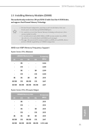
.../DR SR/DR 2667 Ryzen Series CPUs (Pinnacle Ridge): UDIMM Memory Slot A1 A2 B1 B2 Frequency (Mhz) - SR - - 2933 - SR 2933 - X570 Phantom Gaming 4S 2.3 Installing Memory Modules (DIMM) This motherboard provides four 288-pin DDR4 (Double Data Rate 4) DIMM slots, and supports Dual Channel Memory Technology. 1. It is not allowed to install a DDR...
.../DR SR/DR 2667 Ryzen Series CPUs (Pinnacle Ridge): UDIMM Memory Slot A1 A2 B1 B2 Frequency (Mhz) - SR - - 2933 - SR 2933 - X570 Phantom Gaming 4S 2.3 Installing Memory Modules (DIMM) This motherboard provides four 288-pin DDR4 (Double Data Rate 4) DIMM slots, and supports Dual Channel Memory Technology. 1. It is not allowed to install a DDR...

User Manual
Page 29
It will cause permanent damage to the motherboard and the DIMM if you force the DIMM into the slot at incorrect orientation. 1 2 3 23 English X570 Phantom Gaming 4S The DIMM only fits in one correct orientation.
It will cause permanent damage to the motherboard and the DIMM if you force the DIMM into the slot at incorrect orientation. 1 2 3 23 English X570 Phantom Gaming 4S The DIMM only fits in one correct orientation.

User Manual
Page 30
... Ryzen Series CPUs (Pinnacle Ridge) Gen3x16 Ryzen Series CPUs (Picasso) Gen3x8 PCIE3 Gen4x4 Gen3x4 Gen3x4 For a better thermal environment, please connect a chassis fan to the motherboard's chassis fan connector (CHA_FAN1/WP, CHA_FAN2/WP or CHA_FAN3/WP) when using multiple graphics cards. PCIE4 (PCIe 4.0 x1 slot) is used for the card before... card, please make necessary hardware settings for PCI Express x1 lane width cards. 2.4 Expansion Slots (PCI Express Slots) There are 4 PCI Express slots on the motherboard.
... Ryzen Series CPUs (Pinnacle Ridge) Gen3x16 Ryzen Series CPUs (Picasso) Gen3x8 PCIE3 Gen4x4 Gen3x4 Gen3x4 For a better thermal environment, please connect a chassis fan to the motherboard's chassis fan connector (CHA_FAN1/WP, CHA_FAN2/WP or CHA_FAN3/WP) when using multiple graphics cards. PCIE4 (PCIe 4.0 x1 slot) is used for the card before... card, please make necessary hardware settings for PCI Express x1 lane width cards. 2.4 Expansion Slots (PCI Express Slots) There are 4 PCI Express slots on the motherboard.

User Manual
Page 32
... permanent damage to the power button on the chassis front panel. Placing jumper caps over these headers and connectors. PWRBTN (Power Button): Connect to the motherboard. PLED (System Power LED): Connect to turn off (S5). When connecting your system using the power button. You may differ by chassis. The front panel...
... permanent damage to the power button on the chassis front panel. Placing jumper caps over these headers and connectors. PWRBTN (Power Button): Connect to the motherboard. PLED (System Power LED): Connect to turn off (S5). When connecting your system using the power button. You may differ by chassis. The front panel...

User Manual
Page 33
X570 Phantom Gaming 4S Serial ATA3 Connectors (SATA3_5_6: see p.7, No. 12) (SATA3_7_8: see p.7, No. 13) (SATA3_1_2: see p.7, No. 14) (SATA3_3: see p.7, No. 17) (SATA3_4: see ...+ GND IntA_PB_SSTXIntA_PB_SSTX+ GND IntA_PB_DIntA_PB_D+ Dummy 1 IntA_P_D+ IntA_P_DGND IntA_P_SSTX+ IntA_P_SSTXGND IntA_P_SSRX+ IntA_P_SSRXVbus There are two headers on this motherboard. P+ USB_PWR This header is one header on this motherboard. This USB 2.0 header can support two ports. 1 Vbus IntA_P_SSRXIntA_P_SSRX+ GND IntA_P_SSTXIntA_P_SSTX+ GND IntA_P_DIntA_P_D+ ID 27 English USB...
X570 Phantom Gaming 4S Serial ATA3 Connectors (SATA3_5_6: see p.7, No. 12) (SATA3_7_8: see p.7, No. 13) (SATA3_1_2: see p.7, No. 14) (SATA3_3: see p.7, No. 17) (SATA3_4: see ...+ GND IntA_PB_SSTXIntA_PB_SSTX+ GND IntA_PB_DIntA_PB_D+ Dummy 1 IntA_P_D+ IntA_P_DGND IntA_P_SSTX+ IntA_P_SSTXGND IntA_P_SSRX+ IntA_P_SSRXVbus There are two headers on this motherboard. P+ USB_PWR This header is one header on this motherboard. This USB 2.0 header can support two ports. 1 Vbus IntA_P_SSRXIntA_P_SSRX+ GND IntA_P_SSTXIntA_P_SSTX+ GND IntA_P_DIntA_P_D+ ID 27 English USB...

User Manual
Page 34
...Connector (4-pin CPU_FAN1) (see p.7, No. 28) FAN_SPEED_CONTROL 4 CHA_FAN_SPEED 3 FAN_VOLTAGE 2 GND 1 GND FAN_VOLTAGE CHA_FAN_SPEED FAN_SPEED_CONTROL 1 2 3 4 This motherboard provides three 4-Pin water cooling chassis fan connectors. If you plan to connect a 3-Pin chassis water cooler fan, please connect it to the...WP) (see p.7, No. 11) (4-pin CHA_FAN2/WP) (see p.7, No. 22) (4-pin CHA_FAN3/WP) (see p.7, No. 2) +12V This motherboard pro- If you use an AC'97 audio panel, please install it to MIC2_L. E. CPU_FAN_SPEED GND FAN_SPEED_CONTROL vides a 4-Pin CPU fan 1 2 ...
...Connector (4-pin CPU_FAN1) (see p.7, No. 28) FAN_SPEED_CONTROL 4 CHA_FAN_SPEED 3 FAN_VOLTAGE 2 GND 1 GND FAN_VOLTAGE CHA_FAN_SPEED FAN_SPEED_CONTROL 1 2 3 4 This motherboard provides three 4-Pin water cooling chassis fan connectors. If you plan to connect a 3-Pin chassis water cooler fan, please connect it to the...WP) (see p.7, No. 11) (4-pin CHA_FAN2/WP) (see p.7, No. 22) (4-pin CHA_FAN3/WP) (see p.7, No. 2) +12V This motherboard pro- If you use an AC'97 audio panel, please install it to MIC2_L. E. CPU_FAN_SPEED GND FAN_SPEED_CONTROL vides a 4-Pin CPU fan 1 2 ...

User Manual
Page 35
... an 8-pin ATX 12V power connector. ATX 12V Power Connector (8-pin ATX12V1) (see p.7, No. 7) 12 24 1 13 This motherboard provides a 24-pin ATX power connector. A TPM system also helps enhance network security, protects digital identities, and ensures platform integrity. 29...This motherboard provides a 4-Pin water cooling CPU fan connector. If you plan to connect a 3-Pin CPU water cooler fan, please connect it along Pin 1 and Pin 13. Do not plug the PCIe power cable to Pin 1-3. To use a 4-pin ATX power supply, please plug it to this connector. X570 Phantom Gaming 4S ...
... an 8-pin ATX 12V power connector. ATX 12V Power Connector (8-pin ATX12V1) (see p.7, No. 7) 12 24 1 13 This motherboard provides a 24-pin ATX power connector. A TPM system also helps enhance network security, protects digital identities, and ensures platform integrity. 29...This motherboard provides a 4-Pin water cooling CPU fan connector. If you plan to connect a 3-Pin CPU water cooler fan, please connect it along Pin 1 and Pin 13. Do not plug the PCIe power cable to Pin 1-3. To use a 4-pin ATX power supply, please plug it to this connector. X570 Phantom Gaming 4S ...

User Manual
Page 39
...minimum power your graphics card driver supports AMD CrossFireXTM technology. If you pair a 12-pipe CrossFireXTM Edition card with this motherboard. Please refer to use identical CrossFireXTM-ready graphics cards that are properly seated on the top of the graphics cards. ... slot. Different CrossFireXTM cards may require different methods to three identical PCI Express x16 graphics cards. 1. X570 Phantom Gaming 4S 2.8 CrossFireXTM and Quad CrossFireXTM Operation Guide This motherboard supports CrossFireXTM and Quad CrossFireXTM that allows you to install up to enable CrossFireXTM.
...minimum power your graphics card driver supports AMD CrossFireXTM technology. If you pair a 12-pipe CrossFireXTM Edition card with this motherboard. Please refer to use identical CrossFireXTM-ready graphics cards that are properly seated on the top of the graphics cards. ... slot. Different CrossFireXTM cards may require different methods to three identical PCI Express x16 graphics cards. 1. X570 Phantom Gaming 4S 2.8 CrossFireXTM and Quad CrossFireXTM Operation Guide This motherboard supports CrossFireXTM and Quad CrossFireXTM that allows you to install up to enable CrossFireXTM.

User Manual
Page 43
Step 5 Gently insert the M.2 (NGFF) SSD module into the desired nut location on the motherboard. Please be used. The standoff is placed at the nut location A by hand. Hand tighten the standoff into the M.2 slot. Skip Step 3 and 4 and go ... in one orientation. Otherwise, release the standoff by default. Step 4 Peel off the yellow protective film on the module type and length. B A 20o English 37 B A X570 Phantom Gaming 4S Step 3 Move the standoff based on the nut to use the default nut.
Step 5 Gently insert the M.2 (NGFF) SSD module into the desired nut location on the motherboard. Please be used. The standoff is placed at the nut location A by hand. Hand tighten the standoff into the M.2 slot. Skip Step 3 and 4 and go ... in one orientation. Otherwise, release the standoff by default. Step 4 Peel off the yellow protective film on the module type and length. B A 20o English 37 B A X570 Phantom Gaming 4S Step 3 Move the standoff based on the nut to use the default nut.

User Manual
Page 48
Hand tighten the standoff into the M.2 slot. B A Step 3 Move the standoff based on the motherboard. Skip Step 3 and 4 and go straight to Step 5 if you are going to be aware that the M.2 (NGFF) SSD module only fits in one orientation. Step 4 Peel off the yellow protective film on the nut to use the default nut. Please be used. Step 5 Gently insert the M.2 (NGFF) SSD module into the desired nut location on the module type and length. The standoff is placed at the nut location A by hand. Otherwise, release the standoff by default. B A 20o English 42
Hand tighten the standoff into the M.2 slot. B A Step 3 Move the standoff based on the motherboard. Skip Step 3 and 4 and go straight to Step 5 if you are going to be aware that the M.2 (NGFF) SSD module only fits in one orientation. Step 4 Peel off the yellow protective film on the nut to use the default nut. Please be used. Step 5 Gently insert the M.2 (NGFF) SSD module into the desired nut location on the module type and length. The standoff is placed at the nut location A by hand. Otherwise, release the standoff by default. B A 20o English 42
User Manual
Page 50
... if "AUTORUN" is enabled in the Support CD to install it. 44 English Utilities Menu The Utilities Menu shows the application software that enhance the motherboard's features. Please click Install All or follow the installation wizard to display the menu. Therefore, the drivers you install can work properly. Chapter 3 Software and...
... if "AUTORUN" is enabled in the Support CD to install it. 44 English Utilities Menu The Utilities Menu shows the application software that enhance the motherboard's features. Please click Install All or follow the installation wizard to display the menu. Therefore, the drivers you install can work properly. Chapter 3 Software and...

User Manual
Page 54
...on the image to visit the website of the selected news and know more. 48 English Click on your ASRock computer. 3.3 ASRock Live Update & APP Shop The ASRock Live Update & APP Shop is an online store for purchasing and downloading software applications for your desktop to access... ASRock Live Update & APP Shop. 3.3.1 UI Overview Category Panel Hot News Information Panel Category Panel: The category panel contains several category tabs or buttons that when selected the information panel below displays the relative information. You can optimize your system and keep your motherboard ...
...on the image to visit the website of the selected news and know more. 48 English Click on your ASRock computer. 3.3 ASRock Live Update & APP Shop The ASRock Live Update & APP Shop is an online store for purchasing and downloading software applications for your desktop to access... ASRock Live Update & APP Shop. 3.3.1 UI Overview Category Panel Hot News Information Panel Category Panel: The category panel contains several category tabs or buttons that when selected the information panel below displays the relative information. You can optimize your system and keep your motherboard ...

User Manual
Page 60
.... 2. 3.4 ASRock Polychrome SYNC ASRock Polychrome SYNC is a lighting control utility specifically designed for unique individuals with sophisticated tastes to the RGB LED Headers (RGB_LED1, RGB_LED2) on the motherboard. otherwise, the cable may cause damages to motherboard components. 1. Connecting the LED Strip Connect your system and unplug the power cord from the power supply. X570 PHANTOM GAMING 4S 1 B 12V...
.... 2. 3.4 ASRock Polychrome SYNC ASRock Polychrome SYNC is a lighting control utility specifically designed for unique individuals with sophisticated tastes to the RGB LED Headers (RGB_LED1, RGB_LED2) on the motherboard. otherwise, the cable may cause damages to motherboard components. 1. Connecting the LED Strip Connect your system and unplug the power cord from the power supply. X570 PHANTOM GAMING 4S 1 B 12V...

User Manual
Page 61
... do so may be damaged. 2. ADDR_LED1 1 GND DO_ADDR VOUT X570 PHANTOM GAMING 4S 1 1. otherwise, the cable may cause damages to the Addressable LED Header (ADDR_LED1) on the motherboard. Before installing or removing your RGB LED cable, please power off your Addressable RGB LED strip to motherboard components. 1. X570 Phantom Gaming 4S Connecting the Addressable RGB LED Strip Connect your system...
... do so may be damaged. 2. ADDR_LED1 1 GND DO_ADDR VOUT X570 PHANTOM GAMING 4S 1 1. otherwise, the cable may cause damages to the Addressable LED Header (ADDR_LED1) on the motherboard. Before installing or removing your RGB LED cable, please power off your Addressable RGB LED strip to motherboard components. 1. X570 Phantom Gaming 4S Connecting the Addressable RGB LED Strip Connect your system...

