
Quick Installation Guide
Page 4
...3 CPU Fan / Waterpump Fan Connector (CPU_FAN2/WP) 4 2 x 288-pin DDR4 DIMM Slots (DDR4_A1, DDR4_B1) 5 2 x 288-pin DDR4 DIMM Slots (DDR4_A2, DDR4_B2) 6 RGB LED Header (RGB_LED2) 7 ATX Power Connector (ATXPWR1) 8 USB 3.2 Gen1 Header (USB3_7_8) 9 AMD LED Fan USB Header (USB_1) 10 SPI TPM Header (SPI_TPM_J1) 11 Chassis Fan / Waterpump Fan Connector (CHA_FAN1/WP) 12 SATA3 Connector (SATA3_5_6) 13 SATA3 Connector (SATA3_7_8) 14 SATA3 Connector (SATA3_1_2) 15 Power LED and Speaker Header (SPK_PLED1) 16 SATA3 Connector (SATA3_4) 17 SATA3 Connector (SATA3_3) 18 System Panel Header (PANEL1) 19 Clear CMOS...
...3 CPU Fan / Waterpump Fan Connector (CPU_FAN2/WP) 4 2 x 288-pin DDR4 DIMM Slots (DDR4_A1, DDR4_B1) 5 2 x 288-pin DDR4 DIMM Slots (DDR4_A2, DDR4_B2) 6 RGB LED Header (RGB_LED2) 7 ATX Power Connector (ATXPWR1) 8 USB 3.2 Gen1 Header (USB3_7_8) 9 AMD LED Fan USB Header (USB_1) 10 SPI TPM Header (SPI_TPM_J1) 11 Chassis Fan / Waterpump Fan Connector (CHA_FAN1/WP) 12 SATA3 Connector (SATA3_5_6) 13 SATA3 Connector (SATA3_7_8) 14 SATA3 Connector (SATA3_1_2) 15 Power LED and Speaker Header (SPK_PLED1) 16 SATA3 Connector (SATA3_4) 17 SATA3 Connector (SATA3_3) 18 System Panel Header (PANEL1) 19 Clear CMOS...
Quick Installation Guide
Page 7
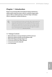
... BIOS software might be updated, the content of this motherboard, please visit our website for specific information about the model you for M.2 Sockets (Optional) • 1 x I/O Panel Shield 5 English You may find the latest VGA cards and CPU support list on ASRock's website without notice. If you require technical support related to quality and endurance. ASRock website http://www.asrock.com. 1.1 Package Contents • ASRock X570 Phantom Gaming 4 Motherboard (ATX Form Factor) • ASRock X570 Phantom Gaming 4 Quick Installation Guide • ASRock X570 Phantom Gaming...
... BIOS software might be updated, the content of this motherboard, please visit our website for specific information about the model you for M.2 Sockets (Optional) • 1 x I/O Panel Shield 5 English You may find the latest VGA cards and CPU support list on ASRock's website without notice. If you require technical support related to quality and endurance. ASRock website http://www.asrock.com. 1.1 Package Contents • ASRock X570 Phantom Gaming 4 Motherboard (ATX Form Factor) • ASRock X570 Phantom Gaming 4 Quick Installation Guide • ASRock X570 Phantom Gaming...
Quick Installation Guide
Page 9
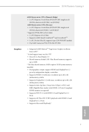
... with HDMI 2.0 and DisplayPort 1.2 Ports • Supports Microsoft PlayReady® English 7 dual at x8 (PCIE1) / x4 (PCIE3))* * Supports NVMe SSD as boot disks • 2 x PCI Express 4.0 x1 Slots • Supports AMD Quad CrossFireXTM and CrossFireXTM • 1 x M.2 Socket (Key E), supports type 2230 WiFi/BT module • 15μ Gold Contact in VGA PCIe Slot (PCIE1) • Integrated AMD RadeonTM Vega Series Graphics in Ryzen Series APU* * Actual support may vary by independent display controllers • Supports HDMI 2.0 with max. X570 Phantom Gaming 4 Graphics AMD Ryzen series...
... with HDMI 2.0 and DisplayPort 1.2 Ports • Supports Microsoft PlayReady® English 7 dual at x8 (PCIE1) / x4 (PCIE3))* * Supports NVMe SSD as boot disks • 2 x PCI Express 4.0 x1 Slots • Supports AMD Quad CrossFireXTM and CrossFireXTM • 1 x M.2 Socket (Key E), supports type 2230 WiFi/BT module • 15μ Gold Contact in VGA PCIe Slot (PCIE1) • Integrated AMD RadeonTM Vega Series Graphics in Ryzen Series APU* * Actual support may vary by independent display controllers • Supports HDMI 2.0 with max. X570 Phantom Gaming 4 Graphics AMD Ryzen series...
Quick Installation Guide
Page 11
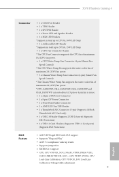
... pin ATX Power Connector • 1 x 8 pin 12V Power Connector • 1 x Front Panel Audio Connector • 1 x AMD LED Fan USB Header • 1 x Thunderbolt AIC Connector (5-pin) (Supports ASRock Thunderbolt AIC Card only) • 1 x USB 2.0 Header (Supports 2 USB 2.0 ports) (Supports ESD Protection) • 2 x USB 3.2 Gen1 Headers (Support 4 USB 3.2 Gen1 ports) (Supports ESD Protection) BIOS Feature • AMI UEFI Legal BIOS with GUI support • Supports "Plug and Play" • ACPI 5.1 compliance wake up events • Supports jumperfree • SMBIOS 2.3 support • CPU...
... pin ATX Power Connector • 1 x 8 pin 12V Power Connector • 1 x Front Panel Audio Connector • 1 x AMD LED Fan USB Header • 1 x Thunderbolt AIC Connector (5-pin) (Supports ASRock Thunderbolt AIC Card only) • 1 x USB 2.0 Header (Supports 2 USB 2.0 ports) (Supports ESD Protection) • 2 x USB 3.2 Gen1 Headers (Support 4 USB 3.2 Gen1 ports) (Supports ESD Protection) BIOS Feature • AMI UEFI Legal BIOS with GUI support • Supports "Plug and Play" • ACPI 5.1 compliance wake up events • Supports jumperfree • SMBIOS 2.3 support • CPU...

Quick Installation Guide
Page 27
...hardware settings for PCI Express x1 lane width cards. PCIE3 (PCIe 4.0 x16 slot) is used for the card before you start the installation. PCIe Slot Configurations Ryzen Series CPUs (Matisse) PCIE1 Gen4x16 Ryzen Series CPUs (Pinnacle Ridge) Gen3x16 Ryzen Series CPUs (Picasso) Gen3x8 PCIE3 Gen4x4 Gen3x4 Gen3x4 For a better thermal environment, please connect a chassis fan to the motherboard's chassis fan connector (CHA_FAN1/WP, CHA_FAN2/WP or CHA_FAN3/WP) when using multiple graphics cards. X570 Phantom Gaming 4 2.4 Expansion Slots (PCI Express Slots) There are 4 PCI Express slots...
...hardware settings for PCI Express x1 lane width cards. PCIE3 (PCIe 4.0 x16 slot) is used for the card before you start the installation. PCIe Slot Configurations Ryzen Series CPUs (Matisse) PCIE1 Gen4x16 Ryzen Series CPUs (Pinnacle Ridge) Gen3x16 Ryzen Series CPUs (Picasso) Gen3x8 PCIE3 Gen4x4 Gen3x4 Gen3x4 For a better thermal environment, please connect a chassis fan to the motherboard's chassis fan connector (CHA_FAN1/WP, CHA_FAN2/WP or CHA_FAN3/WP) when using multiple graphics cards. X570 Phantom Gaming 4 2.4 Expansion Slots (PCI Express Slots) There are 4 PCI Express slots...

Quick Installation Guide
Page 32
... This motherboard provides a 4-Pin water cooling CPU fan connector. Do not plug the PCIe power cable to Pin 1-3. CPU Water Pump Fan Connector (4-pin CPU_FAN2/WP) (see p.1, No. 1) This motherboard provides an 8-pin ATX 12V power connector. English 30 TPM Header (17-pin TPMS1) (see p.1, No. 7) 12 24 1 13 This motherboard provides a 24-pin ATX power connector. A TPM system also helps enhance network security, protects digital identities, and ensures platform integrity. To use a 4-pin ATX power supply, please plug it along Pin 1 and Pin 5. *Warning...
... This motherboard provides a 4-Pin water cooling CPU fan connector. Do not plug the PCIe power cable to Pin 1-3. CPU Water Pump Fan Connector (4-pin CPU_FAN2/WP) (see p.1, No. 1) This motherboard provides an 8-pin ATX 12V power connector. English 30 TPM Header (17-pin TPMS1) (see p.1, No. 7) 12 24 1 13 This motherboard provides a 24-pin ATX power connector. A TPM system also helps enhance network security, protects digital identities, and ensures platform integrity. To use a 4-pin ATX power supply, please plug it along Pin 1 and Pin 5. *Warning...

Quick Installation Guide
Page 33
... allows users to page 42 for further instructions on this header. English 31 Caution: Never install the RGB LED cable in card (AIC) to the Thunderbolt AIC connector via the GPIO cable. * Please install the Thunderbolt™ AIC card to PCIE3 (default slot). * For the further information, please visit www.asrock.com. 1 12V G R B RGB header is used to connect RGB LED extension cable which can securely store keys, digital certificates, passwords...
... allows users to page 42 for further instructions on this header. English 31 Caution: Never install the RGB LED cable in card (AIC) to the Thunderbolt AIC connector via the GPIO cable. * Please install the Thunderbolt™ AIC card to PCIE3 (default slot). * For the further information, please visit www.asrock.com. 1 12V G R B RGB header is used to connect RGB LED extension cable which can securely store keys, digital certificates, passwords...

User Manual
Page 4
... Specifications 2 1.3 Motherboard Layout 7 1.4 I/O Panel 9 Chapter 2 Installation 11 2.1 Installing the CPU 12 2.2 Installing the CPU Fan and Heatsink 14 2.3 Installing Memory Modules (DIMM) 22 2.4 Expansion Slots (PCI Express Slots) 25 2.5 Jumpers Setup 26 2.6 Onboard Headers and Connectors 27 2.7 Post Status Checker 33 2.8 CrossFireXTM and Quad CrossFireXTM Operation Guide 34 2.8.1 Installing Two CrossFireXTM-Ready Graphics Cards 34 2.8.2 Driver Installation and Setup 36 2.9 M.2_SSD (NGFF) Module Installation Guide (M2_1) 37 2.10 M.2 WiFi/BT Module Installation...
... Specifications 2 1.3 Motherboard Layout 7 1.4 I/O Panel 9 Chapter 2 Installation 11 2.1 Installing the CPU 12 2.2 Installing the CPU Fan and Heatsink 14 2.3 Installing Memory Modules (DIMM) 22 2.4 Expansion Slots (PCI Express Slots) 25 2.5 Jumpers Setup 26 2.6 Onboard Headers and Connectors 27 2.7 Post Status Checker 33 2.8 CrossFireXTM and Quad CrossFireXTM Operation Guide 34 2.8.1 Installing Two CrossFireXTM-Ready Graphics Cards 34 2.8.2 Driver Installation and Setup 36 2.9 M.2_SSD (NGFF) Module Installation Guide (M2_1) 37 2.10 M.2 WiFi/BT Module Installation...
User Manual
Page 7
...; ASRock X570 Phantom Gaming 4 Quick Installation Guide • ASRock X570 Phantom Gaming 4 Support CD • 2 x Serial ATA (SATA) Data Cables (Optional) • 3 x Screws for purchasing ASRock X570 Phantom Gaming 4 motherboard, a reliable motherboard produced under ASRock's consistently stringent quality control. Chapter 4 contains the configuration guide of this documentation, Chapter 1 and 2 contains the introduction of the software and utilities. If you require technical support related to this documentation occur, the updated version will be updated, the content of the BIOS...
...; ASRock X570 Phantom Gaming 4 Quick Installation Guide • ASRock X570 Phantom Gaming 4 Support CD • 2 x Serial ATA (SATA) Data Cables (Optional) • 3 x Screws for purchasing ASRock X570 Phantom Gaming 4 motherboard, a reliable motherboard produced under ASRock's consistently stringent quality control. Chapter 4 contains the configuration guide of this documentation, Chapter 1 and 2 contains the introduction of the software and utilities. If you require technical support related to this documentation occur, the updated version will be updated, the content of the BIOS...

User Manual
Page 11
... pin ATX Power Connector • 1 x 8 pin 12V Power Connector • 1 x Front Panel Audio Connector • 1 x AMD LED Fan USB Header • 1 x Thunderbolt AIC Connector (5-pin) (Supports ASRock Thunderbolt AIC Card only) • 1 x USB 2.0 Header (Supports 2 USB 2.0 ports) (Supports ESD Protection) • 2 x USB 3.2 Gen1 Headers (Support 4 USB 3.2 Gen1 ports) (Supports ESD Protection) BIOS Feature • AMI UEFI Legal BIOS with GUI support • Supports "Plug and Play" • ACPI 5.1 compliance wake up events • Supports jumperfree • SMBIOS 2.3 support • CPU...
... pin ATX Power Connector • 1 x 8 pin 12V Power Connector • 1 x Front Panel Audio Connector • 1 x AMD LED Fan USB Header • 1 x Thunderbolt AIC Connector (5-pin) (Supports ASRock Thunderbolt AIC Card only) • 1 x USB 2.0 Header (Supports 2 USB 2.0 ports) (Supports ESD Protection) • 2 x USB 3.2 Gen1 Headers (Support 4 USB 3.2 Gen1 ports) (Supports ESD Protection) BIOS Feature • AMI UEFI Legal BIOS with GUI support • Supports "Plug and Play" • ACPI 5.1 compliance wake up events • Supports jumperfree • SMBIOS 2.3 support • CPU...

User Manual
Page 14
...3 CPU Fan / Waterpump Fan Connector (CPU_FAN2/WP) 4 2 x 288-pin DDR4 DIMM Slots (DDR4_A1, DDR4_B1) 5 2 x 288-pin DDR4 DIMM Slots (DDR4_A2, DDR4_B2) 6 RGB LED Header (RGB_LED2) 7 ATX Power Connector (ATXPWR1) 8 USB 3.2 Gen1 Header (USB3_7_8) 9 AMD LED Fan USB Header (USB_1) 10 SPI TPM Header (SPI_TPM_J1) 11 Chassis Fan / Waterpump Fan Connector (CHA_FAN1/WP) 12 SATA3 Connector (SATA3_5_6) 13 SATA3 Connector (SATA3_7_8) 14 SATA3 Connector (SATA3_1_2) 15 Power LED and Speaker Header (SPK_PLED1) 16 SATA3 Connector (SATA3_4) 17 SATA3 Connector (SATA3_3) 18 System Panel Header (PANEL1) 19 Clear CMOS...
...3 CPU Fan / Waterpump Fan Connector (CPU_FAN2/WP) 4 2 x 288-pin DDR4 DIMM Slots (DDR4_A1, DDR4_B1) 5 2 x 288-pin DDR4 DIMM Slots (DDR4_A2, DDR4_B2) 6 RGB LED Header (RGB_LED2) 7 ATX Power Connector (ATXPWR1) 8 USB 3.2 Gen1 Header (USB3_7_8) 9 AMD LED Fan USB Header (USB_1) 10 SPI TPM Header (SPI_TPM_J1) 11 Chassis Fan / Waterpump Fan Connector (CHA_FAN1/WP) 12 SATA3 Connector (SATA3_5_6) 13 SATA3 Connector (SATA3_7_8) 14 SATA3 Connector (SATA3_1_2) 15 Power LED and Speaker Header (SPK_PLED1) 16 SATA3 Connector (SATA3_4) 17 SATA3 Connector (SATA3_3) 18 System Panel Header (PANEL1) 19 Clear CMOS...

User Manual
Page 36
... network security, protects digital identities, and ensures platform integrity. ATX Power Connector (24-pin ATXPWR1) (see p.7, No. 3) FAN_SPEED_CONTROL CPU_FAN_SPEED FAN_VOLTAGE GND 1 2 34 This motherboard provides a 4-Pin water cooling CPU fan connector. Do not plug the PCIe power cable to connect a 3-Pin CPU water cooler fan, please connect it along Pin 1 and Pin 5. *Warning: Please make sure that the power cable connected is for the CPU and not the graphics card. English 30 To use a 4-pin ATX power supply, please plug it along Pin 1 and Pin...
... network security, protects digital identities, and ensures platform integrity. ATX Power Connector (24-pin ATXPWR1) (see p.7, No. 3) FAN_SPEED_CONTROL CPU_FAN_SPEED FAN_VOLTAGE GND 1 2 34 This motherboard provides a 4-Pin water cooling CPU fan connector. Do not plug the PCIe power cable to connect a 3-Pin CPU water cooler fan, please connect it along Pin 1 and Pin 5. *Warning: Please make sure that the power cable connected is for the CPU and not the graphics card. English 30 To use a 4-pin ATX power supply, please plug it along Pin 1 and Pin...

User Manual
Page 37
... GPIO cable. * Please install the Thunderbolt™ AIC card to PCIE3 (default slot). * For the further information, please visit www.asrock.com. 1 12V G R B RGB header is used to connect RGB LED extension cable which can securely store keys, digital certificates, passwords, and data. Please connect a Thunderbolt™ add-in the wrong orientation; English 31 X570 Phantom Gaming 4 SPI TPM Header (13-pin SPI_TPM_J1) (see p.7, No. 10) Thunderbolt AIC Connector (5-pin TB1...
... GPIO cable. * Please install the Thunderbolt™ AIC card to PCIE3 (default slot). * For the further information, please visit www.asrock.com. 1 12V G R B RGB header is used to connect RGB LED extension cable which can securely store keys, digital certificates, passwords, and data. Please connect a Thunderbolt™ add-in the wrong orientation; English 31 X570 Phantom Gaming 4 SPI TPM Header (13-pin SPI_TPM_J1) (see p.7, No. 10) Thunderbolt AIC Connector (5-pin TB1...

User Manual
Page 40
... CrossFireXTM mode. 5. If you to install up to your graphics card vendor for details. 4. Download the drivers from the AMD's website: www.amd.com 3. Make sure that your power supply unit (PSU) can provide at least the minimum power your graphics card driver supports AMD CrossFireXTM technology. Please refer to three identical PCI Express x16 graphics cards. 1. CrossFire Bridge Step 2 Connect two graphics cards by installing a CrossFire Bridge on the CrossFire Bridge Interconnects on the slots.
... CrossFireXTM mode. 5. If you to install up to your graphics card vendor for details. 4. Download the drivers from the AMD's website: www.amd.com 3. Make sure that your power supply unit (PSU) can provide at least the minimum power your graphics card driver supports AMD CrossFireXTM technology. Please refer to three identical PCI Express x16 graphics cards. 1. CrossFire Bridge Step 2 Connect two graphics cards by installing a CrossFire Bridge on the CrossFire Bridge Interconnects on the slots.
User Manual
Page 42
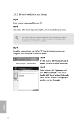
... system. Step 3 Install the required drivers and CATALYST Control Center then restart your computer and boot into OS. The Catalyst Uninstaller is an optional download. AMD Catalyst Control Center Step 4 Double-click the AMD Catalyst Control Center icon in your graphics card and click Apply. Then select Enable AMD CrossFireX and click Apply. English 36 2.8.2 Driver Installation and Setup Step 1 Power on your computer. Please check AMD's website for AMD driver updates.
... system. Step 3 Install the required drivers and CATALYST Control Center then restart your computer and boot into OS. The Catalyst Uninstaller is an optional download. AMD Catalyst Control Center Step 4 Double-click the AMD Catalyst Control Center icon in your graphics card and click Apply. Then select Enable AMD CrossFireX and click Apply. English 36 2.8.2 Driver Installation and Setup Step 1 Power on your computer. Please check AMD's website for AMD driver updates.
User Manual
Page 51
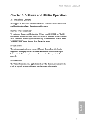
... driver page. X570 Phantom Gaming 4 Chapter 3 Software and Utilities Operation 3.1 Installing Drivers The Support CD that comes with the motherboard contains necessary drivers and useful utilities that the motherboard supports. Running The Support CD To begin using the support CD, insert the CD into your system will be auto-detected and listed on a specific item then follow the order from top to bottom to install it. 45 English Drivers Menu The drivers compatible to your CD-ROM drive...
... driver page. X570 Phantom Gaming 4 Chapter 3 Software and Utilities Operation 3.1 Installing Drivers The Support CD that comes with the motherboard contains necessary drivers and useful utilities that the motherboard supports. Running The Support CD To begin using the support CD, insert the CD into your system will be auto-detected and listed on a specific item then follow the order from top to bottom to install it. 45 English Drivers Menu The drivers compatible to your CD-ROM drive...

User Manual
Page 68
... GFX clock frequency. GFX Clock Frequency (Only for processor with integrated graphics) This item allows you to disable symmetric multithreading. To re-enable SMT, a power cycle is selected, the motherboard will detect the memory module(s) inserted and assign the appropriate frequency automatically. DRAM Timing Configuration Load XMP Setting Load XMP settings to support memory and Infinity Fabric overclocking. "SoC/Uncore OC Mode" need to be used to alter the voltage for the GFX Core Voltage. *The...
... GFX clock frequency. GFX Clock Frequency (Only for processor with integrated graphics) This item allows you to disable symmetric multithreading. To re-enable SMT, a power cycle is selected, the motherboard will detect the memory module(s) inserted and assign the appropriate frequency automatically. DRAM Timing Configuration Load XMP Setting Load XMP settings to support memory and Infinity Fabric overclocking. "SoC/Uncore OC Mode" need to be used to alter the voltage for the GFX Core Voltage. *The...

User Manual
Page 77
PS2 Y-Cable Enable the PS2 Y-Cable or set this option to Auto. 71 English 4.4.5 Super IO Configuration X570 Phantom Gaming 4 Serial Port Enable or disable the Serial port. Serial Port Address Select the address of the Serial port.
PS2 Y-Cable Enable the PS2 Y-Cable or set this option to Auto. 71 English 4.4.5 Super IO Configuration X570 Phantom Gaming 4 Serial Port Enable or disable the Serial port. Serial Port Address Select the address of the Serial port.
User Manual
Page 82
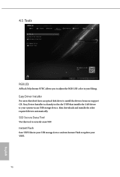
SSD Secure Erase Tool Use this tool to securely erase SSD. Easy Driver Installer For users that installs the LAN driver to your system via an USB storage device, then downloads and installs the other required drivers automatically. Instant Flash Save UEFI files in the UEFI that don't have an optical disk drive to install the drivers from our support CD, Easy Driver Installer is a handy tool in your USB storage device and run Instant Flash to update your liking. 4.5 Tools RGB LED ASRock Polychrome SYNC allows you to adjust the RGB LED color to your UEFI. 76 English
SSD Secure Erase Tool Use this tool to securely erase SSD. Easy Driver Installer For users that installs the LAN driver to your system via an USB storage device, then downloads and installs the other required drivers automatically. Instant Flash Save UEFI files in the UEFI that don't have an optical disk drive to install the drivers from our support CD, Easy Driver Installer is a handy tool in your USB storage device and run Instant Flash to update your liking. 4.5 Tools RGB LED ASRock Polychrome SYNC allows you to adjust the RGB LED color to your UEFI. 76 English
RAID Installation Guide
Page 15
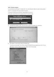
... at this picture. During Windows installation process, when Disk selection page show up, please click . B. Three drivers must be loaded. It should list the USB drive as a UEFI device. This is shown in this point, then please open the boot menu that is the first. A. Click to boot from AMD website. Using SATA/NVMe RAID driver package (version 9.2.0.127) from . STEP 3: Windows installation Insert the USB drive with Windows 10 installation files. Then restart the system...
... at this picture. During Windows installation process, when Disk selection page show up, please click . B. Three drivers must be loaded. It should list the USB drive as a UEFI device. This is shown in this point, then please open the boot menu that is the first. A. Click to boot from AMD website. Using SATA/NVMe RAID driver package (version 9.2.0.127) from . STEP 3: Windows installation Insert the USB drive with Windows 10 installation files. Then restart the system...


