
Quick Installation Guide
Page 1
... use only and subject to the following two conditions: (1) this device may not cause harmful interference, and (2) this documentation, ASRock does not provide warranty of any means, except duplication of merchantability or fitness for any defect or error in the documentation or ... may apply, see www.dtsc.ca.gov/hazardouswaste/ perchlorate" ASRock Website: http://www.asrock.com Copyright Notice: No part of this device must accept any interference received, including interference that may appear in this motherboard contains Perchlorate, a toxic substance controlled in any form or by...
... use only and subject to the following two conditions: (1) this device may not cause harmful interference, and (2) this documentation, ASRock does not provide warranty of any means, except duplication of merchantability or fitness for any defect or error in the documentation or ... may apply, see www.dtsc.ca.gov/hazardouswaste/ perchlorate" ASRock Website: http://www.asrock.com Copyright Notice: No part of this device must accept any interference received, including interference that may appear in this motherboard contains Perchlorate, a toxic substance controlled in any form or by...

Quick Installation Guide
Page 4
Motherboard Layout 1 23 BIOS _FB1 M2_WIFI_1 ATX12V1 CHA_FAN3/WP ATX12V2 X570 Creator 4 5 67 8 CPU_FAN1 AMD_FAN_LED1 1 CPU_FAN2/WP PS2 Keyboard /Mouse USB 3.2 Gen1 T: USB1 B: USB2 ATXPWR1 DDR4_A1 (64 bit, 288-pin module) ...MIC IN M2_1 30 PCIE1 29 PCIE2 Purity SoundTM 4 PCIE3 RoHS CMOS Battery SPI_TPM_J1 1 BIOS ROM PCIE4 SOCKET AM4 1 CHA_FAN1/WP F_USB31_TC_1 AMD Premium X570 SATA3_3_4 SATA3_1_2 USB3_7_8 SATA3_A3_A4 SATA3_A1_A2 M2_2 PCIE5 HD_AUDIO1 1 PCIE6 RGB_HEADER1 1 ADDR_LED1 USB_1_2 1 1 1 USB3_9_10 CLRCMOS1 1 CHA_FAN2 /WP Dr. Debug SPK_PLED1 1 ...
Motherboard Layout 1 23 BIOS _FB1 M2_WIFI_1 ATX12V1 CHA_FAN3/WP ATX12V2 X570 Creator 4 5 67 8 CPU_FAN1 AMD_FAN_LED1 1 CPU_FAN2/WP PS2 Keyboard /Mouse USB 3.2 Gen1 T: USB1 B: USB2 ATXPWR1 DDR4_A1 (64 bit, 288-pin module) ...MIC IN M2_1 30 PCIE1 29 PCIE2 Purity SoundTM 4 PCIE3 RoHS CMOS Battery SPI_TPM_J1 1 BIOS ROM PCIE4 SOCKET AM4 1 CHA_FAN1/WP F_USB31_TC_1 AMD Premium X570 SATA3_3_4 SATA3_1_2 USB3_7_8 SATA3_A3_A4 SATA3_A1_A2 M2_2 PCIE5 HD_AUDIO1 1 PCIE6 RGB_HEADER1 1 ADDR_LED1 USB_1_2 1 1 1 USB3_9_10 CLRCMOS1 1 CHA_FAN2 /WP Dr. Debug SPK_PLED1 1 ...
Quick Installation Guide
Page 8
... documentation occur, the updated version will be available on ASRock's website as well. ASRock website http://www.asrock.com. 1.1 Package Contents • ASRock X570 Creator Motherboard (ATX Form Factor) • ASRock X570 Creator Quick Installation Guide • ASRock X570 Creator Support CD • 4 x Serial ATA (SATA) Data Cables (Optional) • 1 x ASRock SLI_HB_Bridge_2S Card (Optional) • 1 x ASRock WiFi 2.4/5 GHz Antenna • 1 x Right Angle Mini DisplayPort to...
... documentation occur, the updated version will be available on ASRock's website as well. ASRock website http://www.asrock.com. 1.1 Package Contents • ASRock X570 Creator Motherboard (ATX Form Factor) • ASRock X570 Creator Quick Installation Guide • ASRock X570 Creator Support CD • 4 x Serial ATA (SATA) Data Cables (Optional) • 1 x ASRock SLI_HB_Bridge_2S Card (Optional) • 1 x ASRock WiFi 2.4/5 GHz Antenna • 1 x Right Angle Mini DisplayPort to...

Quick Installation Guide
Page 15
... + BT module is an easy-touse wireless local area network (WLAN) adapter to the environment. ASRock WiFi 2.4/5 GHz Antenna 12 English 1.3 WiFi-802.11ax Module and ASRock WiFi 2.4/5 GHz Antenna WiFi-802.11ax + BT Module This motherboard comes with an exclusive WiFi 802.11 a/b/g/n/ax + BT v5.0 module (pre-installed on the rear...
... + BT module is an easy-touse wireless local area network (WLAN) adapter to the environment. ASRock WiFi 2.4/5 GHz Antenna 12 English 1.3 WiFi-802.11ax Module and ASRock WiFi 2.4/5 GHz Antenna WiFi-802.11ax + BT Module This motherboard comes with an exclusive WiFi 802.11 a/b/g/n/ax + BT v5.0 module (pre-installed on the rear...

Quick Installation Guide
Page 17
...Hold components by the edges and do not touch the ICs. • Whenever you uninstall any motherboard settings. • Make sure to unplug the power cord before you and damages to motherboard components. • In order to avoid damage from static electricity to ensure that comes with the ...components. • When placing screws to secure the motherboard to the chassis, please do so may damage the motherboard. 14 English Failure to do not overtighten the screws! Pre-installation Precautions Take note of your chassis to...
...Hold components by the edges and do not touch the ICs. • Whenever you uninstall any motherboard settings. • Make sure to unplug the power cord before you and damages to motherboard components. • In order to avoid damage from static electricity to ensure that comes with the ...components. • When placing screws to secure the motherboard to the chassis, please do so may damage the motherboard. 14 English Failure to do not overtighten the screws! Pre-installation Precautions Take note of your chassis to...

Quick Installation Guide
Page 20
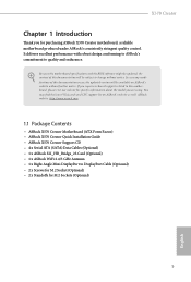
Please turn off the power or remove the power cord before changing a CPU or heatsink. X570 Creator 2.2 Installing the CPU Fan and Heatsink After you install the CPU into this motherboard, it is necessary to install a larger heatsink and cooling fan to improve heat dissipation. You also need to spray thermal grease between the CPU and the heatsink to dissipate heat. Make sure that the CPU and the heatsink are securely fastened and in good contact with each other. Installing the CPU Box Cooler SR1 1 2 17 English
Please turn off the power or remove the power cord before changing a CPU or heatsink. X570 Creator 2.2 Installing the CPU Fan and Heatsink After you install the CPU into this motherboard, it is necessary to install a larger heatsink and cooling fan to improve heat dissipation. You also need to spray thermal grease between the CPU and the heatsink to dissipate heat. Make sure that the CPU and the heatsink are securely fastened and in good contact with each other. Installing the CPU Box Cooler SR1 1 2 17 English

Quick Installation Guide
Page 24
X570 Creator 4 CPU_FAN1 5 RGB LED Cable 4-pin FAN cable CPU_FAN1 +12V AMD_FAN_LED1 *The diagrams shown here are for the orientation of AMD Fan LED Header (AMD_ FAN_LED1). 21 English Please refer to page 36 for reference only. The headers might be in a different position on your motherboard.
X570 Creator 4 CPU_FAN1 5 RGB LED Cable 4-pin FAN cable CPU_FAN1 +12V AMD_FAN_LED1 *The diagrams shown here are for the orientation of AMD Fan LED Header (AMD_ FAN_LED1). 21 English Please refer to page 36 for reference only. The headers might be in a different position on your motherboard.
Quick Installation Guide
Page 28
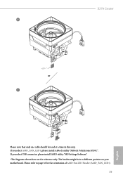
X570 Creator 6 CPU_FAN1 +12V RGB_LED2 or 7 CPU_FAN1 AMD_FAN_LED1 USB_5 Please note that only one cable should be in this step. The headers might be used at a time in a different position on your motherboard. If you select AMD_FAN_LED1, please install ASRock utility "ASRock Polychrome SYNC". Please refer to page 36 for reference only. If you select USB connector, please install AMD utility "SR3 Settings Software". *The diagrams shown here are for the orientation of AMD Fan LED Header (AMD_FAN_LED1). 25 English
X570 Creator 6 CPU_FAN1 +12V RGB_LED2 or 7 CPU_FAN1 AMD_FAN_LED1 USB_5 Please note that only one cable should be in this step. The headers might be used at a time in a different position on your motherboard. If you select AMD_FAN_LED1, please install ASRock utility "ASRock Polychrome SYNC". Please refer to page 36 for reference only. If you select USB connector, please install AMD utility "SR3 Settings Software". *The diagrams shown here are for the orientation of AMD Fan LED Header (AMD_FAN_LED1). 25 English

Quick Installation Guide
Page 29
...- For dual channel configuration, you install the memory modules on DDR4_A2 and DDR4_B2 first for better DRAM compatibility on 2 DIMMs configuration. otherwise, this motherboard and DIMM may be damaged. 4. SR - - 3200 - DR - - 3200 - It is not allowed to install a DDR, DDR2... to install identical (the same brand, speed, size and chip-type) DDR4 DIMM pairs. 2. 2.3 Installing Memory Modules (DIMM) This motherboard provides four 288-pin DDR4 (Double Data Rate 4) DIMM slots, and supports Dual Channel Memory Technology. 1. AMD non-XMP Memory Frequency Support...
...- For dual channel configuration, you install the memory modules on DDR4_A2 and DDR4_B2 first for better DRAM compatibility on 2 DIMMs configuration. otherwise, this motherboard and DIMM may be damaged. 4. SR - - 3200 - DR - - 3200 - It is not allowed to install a DDR, DDR2... to install identical (the same brand, speed, size and chip-type) DDR4 DIMM pairs. 2. 2.3 Installing Memory Modules (DIMM) This motherboard provides four 288-pin DDR4 (Double Data Rate 4) DIMM slots, and supports Dual Channel Memory Technology. 1. AMD non-XMP Memory Frequency Support...

Quick Installation Guide
Page 31
The DIMM only fits in one correct orientation. It will cause permanent damage to the motherboard and the DIMM if you force the DIMM into the slot at incorrect orientation. 1 2 3 28 English
The DIMM only fits in one correct orientation. It will cause permanent damage to the motherboard and the DIMM if you force the DIMM into the slot at incorrect orientation. 1 2 3 28 English

Quick Installation Guide
Page 32
... 4.0 x16 slot) is used for PCI Express x1 lane width cards. PCIE3 (PCIe 2.0 x1 slot) is used for PCI Express x4 lane width graphics cards. X570 Creator 2.4 Expansion Slots (PCI Express Slots) There are 6 PCI Express slots on the motherboard.
... 4.0 x16 slot) is used for PCI Express x1 lane width cards. PCIE3 (PCIe 2.0 x1 slot) is used for PCI Express x4 lane width graphics cards. X570 Creator 2.4 Expansion Slots (PCI Express Slots) There are 6 PCI Express slots on the motherboard.

Quick Installation Guide
Page 33
English 30 Ryzen series CPUs (Pinnacle Ridge) Single Graphics Card PCIE1 Gen3x16 Two Graphics Cards in CrossFireXTM or SLITM Mode Gen3x8 PCIE4 N/A Gen3x8 Three Graphics Cards in 3-Way CrossFireXTM Mode Gen3x8 Gen3x8 PCIE6 N/A N/A Gen4x4 Ryzen series CPUs (Picasso) Single Graphics Card PCIE1 Gen3x8 N/A PCIE4 N/A N/A PCIE6 N/A Gen4x4 For a better thermal environment, please connect a chassis fan to the motherboard's chassis fan connector (CHA_FAN1/WP, CHA_FAN2/WP or CHA_FAN3/WP) when using multiple graphics cards.
English 30 Ryzen series CPUs (Pinnacle Ridge) Single Graphics Card PCIE1 Gen3x16 Two Graphics Cards in CrossFireXTM or SLITM Mode Gen3x8 PCIE4 N/A Gen3x8 Three Graphics Cards in 3-Way CrossFireXTM Mode Gen3x8 Gen3x8 PCIE6 N/A N/A Gen4x4 Ryzen series CPUs (Picasso) Single Graphics Card PCIE1 Gen3x8 N/A PCIE4 N/A N/A PCIE6 N/A Gen4x4 For a better thermal environment, please connect a chassis fan to the motherboard's chassis fan connector (CHA_FAN1/WP, CHA_FAN2/WP or CHA_FAN3/WP) when using multiple graphics cards.

Quick Installation Guide
Page 35
... system is in S1/S3 sleep state. 2.6 Onboard Headers and Connectors Onboard headers and connectors are matched correctly. PLED (System Power LED): Connect to the motherboard. The LED is on the chassis front panel. The LED is on the chassis front panel. Do NOT place jumper caps over the headers and...
... system is in S1/S3 sleep state. 2.6 Onboard Headers and Connectors Onboard headers and connectors are matched correctly. PLED (System Power LED): Connect to the motherboard. The LED is on the chassis front panel. The LED is on the chassis front panel. Do NOT place jumper caps over the headers and...

Quick Installation Guide
Page 36
...SATA3_1 USB 2.0 Header (9-pin USB_1_2) (see p.1, No. 25) USB_PWR PP+ GND DUMMY 1 GND P+ PUSB_PWR There is a header on this motherboard. Please connect the chassis power LED and the chassis speaker to 6.0 Gb/s data transfer rate. *To minimize the boot time, use AMD®... 16) SPEAKER DUMMY DUMMY +5V 1 PLED+ PLED+ PLED- These eight SATA3 connectors support SATA data cables for internal storage devices with up to this header. X570 Creator Power LED and Speaker Header (7-pin SPK_PLED1) (see p.1, No. 20) Serial ATA3 Connectors (SATA3_1_2: see p.1, No. 13) (SATA3_3_4: see p.1, No. ...
...SATA3_1 USB 2.0 Header (9-pin USB_1_2) (see p.1, No. 25) USB_PWR PP+ GND DUMMY 1 GND P+ PUSB_PWR There is a header on this motherboard. Please connect the chassis power LED and the chassis speaker to 6.0 Gb/s data transfer rate. *To minimize the boot time, use AMD®... 16) SPEAKER DUMMY DUMMY +5V 1 PLED+ PLED+ PLED- These eight SATA3 connectors support SATA data cables for internal storage devices with up to this header. X570 Creator Power LED and Speaker Header (7-pin SPK_PLED1) (see p.1, No. 20) Serial ATA3 Connectors (SATA3_1_2: see p.1, No. 13) (SATA3_3_4: see p.1, No. ...

Quick Installation Guide
Page 37
Connect Ground (GND) to connect them for the AC'97 audio panel. E. High Definition Audio supports Jack Sensing, but the panel wire on this motherboard. Please follow the instructions in the Realtek Control panel and adjust "Recording Volume". You don't need to Ground (GND). If you use an AC'97 ...
Connect Ground (GND) to connect them for the AC'97 audio panel. E. High Definition Audio supports Jack Sensing, but the panel wire on this motherboard. Please follow the instructions in the Realtek Control panel and adjust "Recording Volume". You don't need to Ground (GND). If you use an AC'97 ...

Quick Installation Guide
Page 38
...(4-pin CPU_FAN2/WP) (see p.1, No. 3) FAN_SPEED_CONTROL 4 CHA_FAN_SPEED 3 FAN_VOLTAGE 2 GND 1 GND FAN_VOLTAGE FAN_SPEED FAN_SPEED_CONTROL This motherboard provides three 4-Pin water cooling chassis fan connectors. If you plan to this connector. 35 English Do not plug the ... 12V 4 1 power connector. X570 Creator Chassis Water Pump Fan Connectors (4-pin CHA_FAN1/WP) (see p.1, No. 11) (4-pin CHA_FAN2/WP) (see p.1, No. 23) (4-pin CHA_FAN3/WP) (see p.1, No. 4) FAN_SPEED_CONTROL CPU_FAN_SPEED FAN_VOLTAGE GND 1 2 34 This motherboard provides a 4-Pin water cooling...
...(4-pin CPU_FAN2/WP) (see p.1, No. 3) FAN_SPEED_CONTROL 4 CHA_FAN_SPEED 3 FAN_VOLTAGE 2 GND 1 GND FAN_VOLTAGE FAN_SPEED FAN_SPEED_CONTROL This motherboard provides three 4-Pin water cooling chassis fan connectors. If you plan to this connector. 35 English Do not plug the ... 12V 4 1 power connector. X570 Creator Chassis Water Pump Fan Connectors (4-pin CHA_FAN1/WP) (see p.1, No. 11) (4-pin CHA_FAN2/WP) (see p.1, No. 23) (4-pin CHA_FAN3/WP) (see p.1, No. 4) FAN_SPEED_CONTROL CPU_FAN_SPEED FAN_VOLTAGE GND 1 2 34 This motherboard provides a 4-Pin water cooling...

Quick Installation Guide
Page 40
... is used to connect Addressable LED extension cable which allows users to choose from various LED lighting effects. This motherboard provides a DisplayPort 1.4 Input connector. This connector is used to connect a DisplayPort compatible device. X570 Creator RGB LED Header (4-pin RGB_HEADER1) (see p.1, No. 27) 1 12V G R B Addressable LED Header (3-pin ADDR_LED1) (see p.1, No. 26) 1 GND...
... is used to connect Addressable LED extension cable which allows users to choose from various LED lighting effects. This motherboard provides a DisplayPort 1.4 Input connector. This connector is used to connect a DisplayPort compatible device. X570 Creator RGB LED Header (4-pin RGB_HEADER1) (see p.1, No. 27) 1 12V G R B Addressable LED Header (3-pin ADDR_LED1) (see p.1, No. 26) 1 GND...

Quick Installation Guide
Page 41
... is workable only when you power off the system, reset the system, clear the CMOS values or flash the BIOS. English 38 2.7 Smart Switches The motherboard has four smart switches: Power Button, Reset Button, Clear CMOS Button and BIOS Flashback Button, allowing users to quickly turn on /off your computer and...
... is workable only when you power off the system, reset the system, clear the CMOS values or flash the BIOS. English 38 2.7 Smart Switches The motherboard has four smart switches: Power Button, Reset Button, Clear CMOS Button and BIOS Flashback Button, allowing users to quickly turn on /off your computer and...

Quick Installation Guide
Page 42
... sure the file system of X: USB flash drive. 5. English USB BIOS Flashback port 39 X570 Creator BIOS Flashback Button (BIOS_FB1) (see p.3, No. 19) BIOS Flashback Button allows users to the motherboard. Download the latest BIOS file from the zip file. 4. Rename the file to "creative.... plug your USB flash drive. Press the BIOS Flashback Switch for about three seconds. Extract BIOS file from ASRock's website : http://www.asrock.com. 2. Then the LED starts to the USB BIOS Flashback port. ASRock BIOS Flashback feature allows you plug the USB drive to blink. 8.
... sure the file system of X: USB flash drive. 5. English USB BIOS Flashback port 39 X570 Creator BIOS Flashback Button (BIOS_FB1) (see p.3, No. 19) BIOS Flashback Button allows users to the motherboard. Download the latest BIOS file from the zip file. 4. Rename the file to "creative.... plug your USB flash drive. Press the BIOS Flashback Switch for about three seconds. Extract BIOS file from ASRock's website : http://www.asrock.com. 2. Then the LED starts to the USB BIOS Flashback port. ASRock BIOS Flashback feature allows you plug the USB drive to blink. 8.

Quick Installation Guide
Page 50
...standoff into the M.2 slot. Align and gently insert the M.2 (NGFF) SSD module into the desired nut location on the motherboard. Please do not overtighten the screw as this might damage the module. 47 English Peel off the orange protective film on ... B A C B A 20o C B NUT2 NUT1 Step 4 Prepare the M.2 standoff that the M.2 (NGFF) SSD module only fits in one orientation. Please be used. X570 Creator Step 3 1 Before installing a M.2 (NGFF) SSD module, please loosen the screws to 2 remove the M.2 heatsink. 1 *Please remove the blue plastic film from the silicone...
...standoff into the M.2 slot. Align and gently insert the M.2 (NGFF) SSD module into the desired nut location on the motherboard. Please do not overtighten the screw as this might damage the module. 47 English Peel off the orange protective film on ... B A C B A 20o C B NUT2 NUT1 Step 4 Prepare the M.2 standoff that the M.2 (NGFF) SSD module only fits in one orientation. Please be used. X570 Creator Step 3 1 Before installing a M.2 (NGFF) SSD module, please loosen the screws to 2 remove the M.2 heatsink. 1 *Please remove the blue plastic film from the silicone...


