User Manual
Page 5
... 1 1.2 Specifications 2 1.3 Motherboard Layout 6 1.4 I/O Panel 8 Chapter 2 Installation 9 2.1 Installing the CPU 10 2.2 Installing the CPU Fan and Heatsink 12 2.3 Installing Memory Modules (DIMM) 20 2.4 Expansion Slots (PCIe Slots) 24 2.5 Jumpers Setup 25 2.6 Onboard Headers and Connectors 26 2.7 M.2_SSD (NGFF) Module Installation Guide 30 Chapter 3 Software and Utilities Operation 34 3.1 Installing Drivers 34 3.2 ASRock Motherboard Utility (A-Tuning) 35 3.2.1 Installing ASRock Motherboard Utility (A-Tuning) 35 3.2.2 Using ASRock Motherboard Utility (A-Tuning...
... 1 1.2 Specifications 2 1.3 Motherboard Layout 6 1.4 I/O Panel 8 Chapter 2 Installation 9 2.1 Installing the CPU 10 2.2 Installing the CPU Fan and Heatsink 12 2.3 Installing Memory Modules (DIMM) 20 2.4 Expansion Slots (PCIe Slots) 24 2.5 Jumpers Setup 25 2.6 Onboard Headers and Connectors 26 2.7 M.2_SSD (NGFF) Module Installation Guide 30 Chapter 3 Software and Utilities Operation 34 3.1 Installing Drivers 34 3.2 ASRock Motherboard Utility (A-Tuning) 35 3.2.1 Installing ASRock Motherboard Utility (A-Tuning) 35 3.2.2 Using ASRock Motherboard Utility (A-Tuning...
User Manual
Page 7
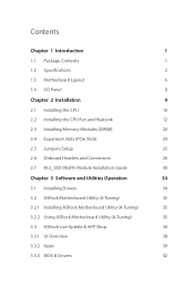
... change without further notice. In this manual occur, the updated version will be available on ASRock's website as well. In case any modifications of this manual, Chapter 1 and 2 contains the introduction of the software and utilities. Chapter 4 contains the configuration guide of this motherboard, please visit our website for specific information about the model you for M.2 Socket (Optional) 1 English You may find the latest VGA cards and CPU support list on ASRock...
... change without further notice. In this manual occur, the updated version will be available on ASRock's website as well. In case any modifications of this manual, Chapter 1 and 2 contains the introduction of the software and utilities. Chapter 4 contains the configuration guide of this motherboard, please visit our website for specific information about the model you for M.2 Socket (Optional) 1 English You may find the latest VGA cards and CPU support list on ASRock...
User Manual
Page 10
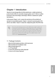
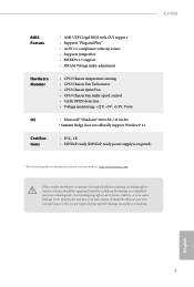
... series APU)* * Supports NVMe SSD as boot disks * Supports ASRock U.2 Kit Connector • 1 x COM Port Header • 1 x Chassis Intrusion and Speaker Header • 1 x CPU Fan Connector (4-pin) * The CPU Fan Connector supports the CPU fan of maximum 1A (12W) fan power. • 2 x Chassis Fan Connectors (1 x 4-pin, 1 x 3-pin) * The Chassis Fan Connector supports the chassis fan of maximum 1A (12W) fan power. • 1 x 24 pin ATX Power Connector • 1 x 4 pin 12V Power Connector • 1 x Front Panel Audio Connector • 2 x USB 2.0 Headers (Support 4 USB 2.0 ports) (Supports...
... series APU)* * Supports NVMe SSD as boot disks * Supports ASRock U.2 Kit Connector • 1 x COM Port Header • 1 x Chassis Intrusion and Speaker Header • 1 x CPU Fan Connector (4-pin) * The CPU Fan Connector supports the CPU fan of maximum 1A (12W) fan power. • 2 x Chassis Fan Connectors (1 x 4-pin, 1 x 3-pin) * The Chassis Fan Connector supports the chassis fan of maximum 1A (12W) fan power. • 1 x 24 pin ATX Power Connector • 1 x 4 pin 12V Power Connector • 1 x Front Panel Audio Connector • 2 x USB 2.0 Headers (Support 4 USB 2.0 ports) (Supports...
User Manual
Page 11
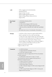
... power supply is required) * For detailed product information, please visit our website: http://www.asrock.com Please realize that there is a certain risk involved with GUI support • Supports "Plug and Play" • ACPI 5.1 compliance wake up events • Supports jumperfree • SMBIOS 2.3 support • DRAM Voltage multi-adjustment Hardware Monitor • CPU/Chassis temperature sensing • CPU/Chassis Fan Tachometer • CPU/Chassis Quiet Fan • CPU/Chassis Fan multi-speed control • CASE OPEN detection • Voltage monitoring...
... power supply is required) * For detailed product information, please visit our website: http://www.asrock.com Please realize that there is a certain risk involved with GUI support • Supports "Plug and Play" • ACPI 5.1 compliance wake up events • Supports jumperfree • SMBIOS 2.3 support • DRAM Voltage multi-adjustment Hardware Monitor • CPU/Chassis temperature sensing • CPU/Chassis Fan Tachometer • CPU/Chassis Quiet Fan • CPU/Chassis Fan multi-speed control • CASE OPEN detection • Voltage monitoring...
User Manual
Page 13
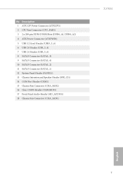
... Power Connector (ATX12V1) 2 CPU Fan Connector (CPU_FAN1) 3 2 x 288-pin DDR4 DIMM Slots (DDR4_A1, DDR4_A2) 4 ATX Power Connector (ATXPWR1) 5 USB 3.2 Gen1 Header (USB3_5_6) 6 USB 2.0 Header (USB_3_4) 7 USB 2.0 Header (USB_5_6) 8 SATA3 Connector (SATA3_3) 9 SATA3 Connector (SATA3_4) 10 SATA3 Connector (SATA3_2) 11 SATA3 Connector (SATA3_1) 12 System Panel Header (PANEL1) 13 Chassis Intrusion and Speaker Header (SPK_CI1) 14 COM Port Header (COM1) 15 Chassis Fan Connector (CHA_FAN2) 16 Clear CMOS Header (CLRCMOS1) 17 Front Panel Audio Header (HD_AUDIO1) 18 Chassis Fan Connector (CHA_FAN1) X370M...
... Power Connector (ATX12V1) 2 CPU Fan Connector (CPU_FAN1) 3 2 x 288-pin DDR4 DIMM Slots (DDR4_A1, DDR4_A2) 4 ATX Power Connector (ATXPWR1) 5 USB 3.2 Gen1 Header (USB3_5_6) 6 USB 2.0 Header (USB_3_4) 7 USB 2.0 Header (USB_5_6) 8 SATA3 Connector (SATA3_3) 9 SATA3 Connector (SATA3_4) 10 SATA3 Connector (SATA3_2) 11 SATA3 Connector (SATA3_1) 12 System Panel Header (PANEL1) 13 Chassis Intrusion and Speaker Header (SPK_CI1) 14 COM Port Header (COM1) 15 Chassis Fan Connector (CHA_FAN2) 16 Clear CMOS Header (CLRCMOS1) 17 Front Panel Audio Header (HD_AUDIO1) 18 Chassis Fan Connector (CHA_FAN1) X370M...
User Manual
Page 30
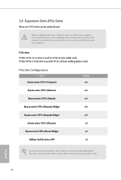
... installation. English 24 PCIe Slot Configurations CPU Ryzen series CPUs (Vermeer) PCIE2 x16 Ryzen series CPUs (Matisse) x16 Ryzen series APUs (Renoir) x16 Ryzen series CPUs (Pinnacle Ridge) x16 Ryzen series CPUs (Summit Ridge) x16 Ryzen series CPUs (Picasso) x8 Ryzen series CPUs (Raven Ridge) x8 Athlon 2xxGE series APU x4 For a better thermal environment, please connect a chassis fan to the motherboard's chassis fan connector (CHA_FAN1 or CHA_FAN2 ) when using multiple graphics cards...
... installation. English 24 PCIe Slot Configurations CPU Ryzen series CPUs (Vermeer) PCIE2 x16 Ryzen series CPUs (Matisse) x16 Ryzen series APUs (Renoir) x16 Ryzen series CPUs (Pinnacle Ridge) x16 Ryzen series CPUs (Summit Ridge) x16 Ryzen series CPUs (Picasso) x8 Ryzen series CPUs (Raven Ridge) x8 Athlon 2xxGE series APU x4 For a better thermal environment, please connect a chassis fan to the motherboard's chassis fan connector (CHA_FAN1 or CHA_FAN2 ) when using multiple graphics cards...
User Manual
Page 31
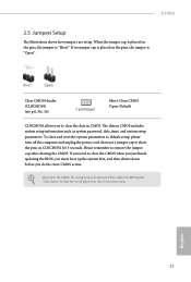
... on the pins, the jumper is "Open". The data in CMOS. To clear and reset the system parameters to default setup, please turn off the computer and unplug the power cord, then use a jumper cap to clear the data in CMOS includes system setup information such as system password, date, time, and system setup parameters. Please adjust the BIOS option "Clear Status" to remove the jumper cap after clearing the CMOS. English 25...
... on the pins, the jumper is "Open". The data in CMOS. To clear and reset the system parameters to default setup, please turn off the computer and unplug the power cord, then use a jumper cap to clear the data in CMOS includes system setup information such as system password, date, time, and system setup parameters. Please adjust the BIOS option "Clear Status" to remove the jumper cap after clearing the CMOS. English 25...
User Manual
Page 33
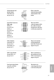
... connectors support SATA data cables for connecting audio devices to the front audio panel. 27 English X370M Chassis Intrusion and Speaker Header (7-pin SPK_CI1) (see p.6, No. 13) Serial ATA3 Connectors Right Angle: (SATA3_1: see p.6, No. 11) (SATA3_2: see p.6, No. 10) (SATA3_3: see p.6, No. 8) (SATA3_4: see p.6, No. 9) SPEAKER DUMMY DUMMY +5V 1 SIGNAL GND DUMMY SATA3_1 SATA3_3 SATA3_2 SATA3_4 Please connect the chassis intrusion and the chassis speaker to 6.0 Gb/s data transfer rate. USB 2.0 Headers (9-pin...
... connectors support SATA data cables for connecting audio devices to the front audio panel. 27 English X370M Chassis Intrusion and Speaker Header (7-pin SPK_CI1) (see p.6, No. 13) Serial ATA3 Connectors Right Angle: (SATA3_1: see p.6, No. 11) (SATA3_2: see p.6, No. 10) (SATA3_3: see p.6, No. 8) (SATA3_4: see p.6, No. 9) SPEAKER DUMMY DUMMY +5V 1 SIGNAL GND DUMMY SATA3_1 SATA3_3 SATA3_2 SATA3_4 Please connect the chassis intrusion and the chassis speaker to 6.0 Gb/s data transfer rate. USB 2.0 Headers (9-pin...
User Manual
Page 34
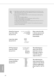
... motherboard provides a 4-Pin CPU fan (Quiet Fan) connector. This motherboard provides a 24-pin ATX power connector. B. If you use a 20-pin ATX power supply, please plug it along Pin 1 and Pin 13. English 28 C. If you plan to connect a 3-Pin CPU fan, please connect it to Pin 1-3. Connect Mic_IN (MIC) to the ground pin. High Definition Audio supports Jack Sensing, but the panel wire on the chassis must support HDA to the "FrontMic" Tab in our manual and chassis manual to OUT2_L. D. To use an AC'97 audio panel, please install...
... motherboard provides a 4-Pin CPU fan (Quiet Fan) connector. This motherboard provides a 24-pin ATX power connector. B. If you use a 20-pin ATX power supply, please plug it along Pin 1 and Pin 13. English 28 C. If you plan to connect a 3-Pin CPU fan, please connect it to Pin 1-3. Connect Mic_IN (MIC) to the ground pin. High Definition Audio supports Jack Sensing, but the panel wire on the chassis must support HDA to the "FrontMic" Tab in our manual and chassis manual to OUT2_L. D. To use an AC'97 audio panel, please install...
User Manual
Page 40
.... 34 English Drivers Menu The drivers compatible to display the menu. Therefore, the drivers you install can work properly. Running The Support CD To begin using the support CD, insert the CD into your computer. Click on the support CD driver page. If the Main Menu does not appear automatically, locate and double click on the file "ASRSETUP.EXE" in your CD-ROM drive. Chapter 3 Software and Utilities Operation 3.1 Installing Drivers The Support CD that...
.... 34 English Drivers Menu The drivers compatible to display the menu. Therefore, the drivers you install can work properly. Running The Support CD To begin using the support CD, insert the CD into your computer. Click on the support CD driver page. If the Main Menu does not appear automatically, locate and double click on the file "ASRSETUP.EXE" in your CD-ROM drive. Chapter 3 Software and Utilities Operation 3.1 Installing Drivers The Support CD that...

User Manual
Page 50
...: Main For setting system time/date information OC Tweaker For overclocking configurations Advanced For advanced system configurations Tool Useful tools H/W Monitor Displays current hardware status Boot For configuring boot settings and boot priority Security For security settings Exit Exit the current screen or the UEFI Setup Utility English 44 If you see on your system. Chapter 4 UEFI SETUP UTILITY 4.1 Introduction This section explains how to use the UEFI SETUP UTILITY to enter the UEFI SETUP UTILITY after you power on...
...: Main For setting system time/date information OC Tweaker For overclocking configurations Advanced For advanced system configurations Tool Useful tools H/W Monitor Displays current hardware status Boot For configuring boot settings and boot priority Security For security settings Exit Exit the current screen or the UEFI Setup Utility English 44 If you see on your system. Chapter 4 UEFI SETUP UTILITY 4.1 Introduction This section explains how to use the UEFI SETUP UTILITY to enter the UEFI SETUP UTILITY after you power on...
User Manual
Page 53
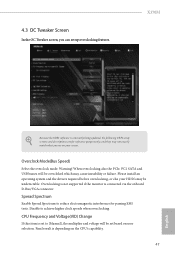
... is connected via the onboard D-Bus/VGA connector. Warning! Please install an operating system and the drivers required before overclocking, or else your screen. Overclock Mode(Bus Speed) Select the overclock mode. When overclocking also the PCIe, PCI, SATA and USB busses will be undetectable. CPU Frequency and Voltage(VID) Change If this item is constantly being updated, the following UEFI setup screens and descriptions are for passing EMI tests. X370M Because the UEFI software is set to [Manual], the multiplier and voltage will...
... is connected via the onboard D-Bus/VGA connector. Warning! Please install an operating system and the drivers required before overclocking, or else your screen. Overclock Mode(Bus Speed) Select the overclock mode. When overclocking also the PCIe, PCI, SATA and USB busses will be undetectable. CPU Frequency and Voltage(VID) Change If this item is constantly being updated, the following UEFI setup screens and descriptions are for passing EMI tests. X370M Because the UEFI software is set to [Manual], the multiplier and voltage will...
User Manual
Page 56
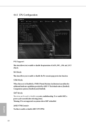
Coniguration options: [Enabled] and [Disabled]. SVM Mode When this to [Enabled], a VMM (Virtual Machine Architecture)can be used to disable symmetric multithreading. The default value is needed after selecting [Auto]. To re-enable SMT, a power cycle is [Enabled]. Warning: S3 is not supported on systems where SMT is set to enable or disable AMD CPU fTPM. 50 English AMD fTPM Switch Use this is disabled. 4.4.1 CPU Configuration PSS Support This item allows you to enable or disable the generation...
Coniguration options: [Enabled] and [Disabled]. SVM Mode When this to [Enabled], a VMM (Virtual Machine Architecture)can be used to disable symmetric multithreading. The default value is needed after selecting [Auto]. To re-enable SMT, a power cycle is [Enabled]. Warning: S3 is not supported on systems where SMT is set to enable or disable AMD CPU fTPM. 50 English AMD fTPM Switch Use this is disabled. 4.4.1 CPU Configuration PSS Support This item allows you to enable or disable the generation...
User Manual
Page 60
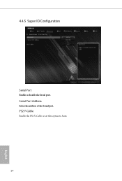
PS2 Y-Cable Enable the PS2 Y-Cable or set this option to Auto. 54 English Serial Port Address Select the address of the Serial port. 4.4.5 Super IO Configuration Serial Port Enable or disable the Serial port.
PS2 Y-Cable Enable the PS2 Y-Cable or set this option to Auto. 54 English Serial Port Address Select the address of the Serial port. 4.4.5 Super IO Configuration Serial Port Enable or disable the Serial port.
User Manual
Page 62
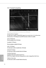
... item to enable or disable Platform Hierarchy. 56 English SHA-1 PCR Bank Use this item to change State of your connected TPM module. TCG EFI protocol and INT1A interface will not show Security Device. 4.4.7 Trusted Computing NOTE: Options vary depending on the version of the Device. NOTE: Your computer will reboot during restart in order to enable or disable BIOS support for the...
... item to enable or disable Platform Hierarchy. 56 English SHA-1 PCR Bank Use this item to change State of your connected TPM module. TCG EFI protocol and INT1A interface will not show Security Device. 4.4.7 Trusted Computing NOTE: Options vary depending on the version of the Device. NOTE: Your computer will reboot during restart in order to enable or disable BIOS support for the...
User Manual
Page 63
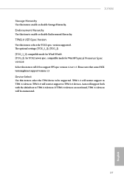
... support version 1.3. Device Select Use this item to enable or disable Endorsement Hierarchy. If TPM 2.0 devices are not found, TPM 1.2 devices will support both with the default set to TPM 2.0 devices. TPM2.0 UEFI Spec Version Use this item to enable or disable Storage Hierarchy. Auto will be supported. X370M Storage Hierarchy Use this item to select the TCG2 spec. TPM 2.0 will restrict support to TPM 1.2 devices. version supported. The optional settings: [TCG_1_2]; [TCG_2]. [TCG_1_2]: compatible mode for Win8/Win10. [TCG_2]: for Win10Physical Presence Spec version...
... support version 1.3. Device Select Use this item to enable or disable Endorsement Hierarchy. If TPM 2.0 devices are not found, TPM 1.2 devices will support both with the default set to TPM 2.0 devices. TPM2.0 UEFI Spec Version Use this item to enable or disable Storage Hierarchy. Auto will be supported. X370M Storage Hierarchy Use this item to select the TCG2 spec. TPM 2.0 will restrict support to TPM 1.2 devices. version supported. The optional settings: [TCG_1_2]; [TCG_2]. [TCG_1_2]: compatible mode for Win8/Win10. [TCG_2]: for Win10Physical Presence Spec version...
User Manual
Page 71
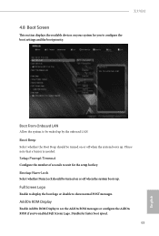
... boot speed. 65 English Setup Prompt Timeout Configure the number of seconds to show normal POST messages. Bootup Num-Lock Select whether Num Lock should be waked up . Full Screen Logo Enable to display the boot logo or disable to wait for the setup hot key. X370M 4.8 Boot Screen This section displays the available devices on your system for you 've enabled Full Screen Logo. Boot Beep Select whether the Boot Beep should be turned...
... boot speed. 65 English Setup Prompt Timeout Configure the number of seconds to show normal POST messages. Bootup Num-Lock Select whether Num Lock should be waked up . Full Screen Logo Enable to display the boot logo or disable to wait for the setup hot key. X370M 4.8 Boot Screen This section displays the available devices on your system for you 've enabled Full Screen Logo. Boot Beep Select whether the Boot Beep should be turned...
RAID Installation Guide
Page 2
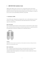
... you make a SATA driver diskette, press or to enter BIOS setup to a second drive. WARNING!! Hot-Plug any fault tolerance. RAID 1 (Data Mirroring) RAID 1 is a method combining two or more hard disk drives into one logical unit. For optimal performance, please install identical drives of the data in parallel, interleaved stacks. Although RAID 0 function can start to use the onboard RAID Option ROM Utility to configure RAID. 1.1 Introduction to RAID The term "RAID" stands for you...
... you make a SATA driver diskette, press or to enter BIOS setup to a second drive. WARNING!! Hot-Plug any fault tolerance. RAID 1 (Data Mirroring) RAID 1 is a method combining two or more hard disk drives into one logical unit. For optimal performance, please install identical drives of the data in parallel, interleaved stacks. Although RAID 0 function can start to use the onboard RAID Option ROM Utility to configure RAID. 1.1 Introduction to RAID The term "RAID" stands for you...
RAID Installation Guide
Page 8
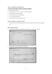
...; Easy RAID Installer F. Go to enter UEFI setup utility. Click to finish the driver copy process. Follow instructions to find the driver inside your USB flash disk. STEP 3.1: Copy RAID driver to a USB flash drive You can choose either STEP 3.1 or STEP 3.2 to finish the configuration. STEP 3.2: Download driver from ASRock's website and unzip the file into the DVD-ROM drive. Please download the "SATA Floppy Imaged driver" from ASRock's website A. C. A. Plug a USB drive into one of the USB port. During Windows installation process, when Disk selection page...
...; Easy RAID Installer F. Go to enter UEFI setup utility. Click to finish the driver copy process. Follow instructions to find the driver inside your USB flash disk. STEP 3.1: Copy RAID driver to a USB flash drive You can choose either STEP 3.1 or STEP 3.2 to finish the configuration. STEP 3.2: Download driver from ASRock's website and unzip the file into the DVD-ROM drive. Please download the "SATA Floppy Imaged driver" from ASRock's website A. C. A. Plug a USB drive into one of the USB port. During Windows installation process, when Disk selection page...
RAID Installation Guide
Page 12
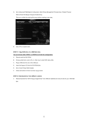
.... *Be sure to exit. Plug a USB drive into the DVD-ROM drive. Insert the Support CD into one of the USB port. Click to save to delete the existing disk arrays before creating a new array. STEP 2.1: Copy RAID driver to a USB flash drive You can choose either STEP2.1 or STEP2.2 to enter UEFI setup utility. H. C. B. E. Please install the DVD-ROM. During system boot, press or key to finish the configuration. Please download the "SATA Floppy Imaged driver" from ASRock's website A.
.... *Be sure to exit. Plug a USB drive into the DVD-ROM drive. Insert the Support CD into one of the USB port. Click to save to delete the existing disk arrays before creating a new array. STEP 2.1: Copy RAID driver to a USB flash drive You can choose either STEP2.1 or STEP2.2 to enter UEFI setup utility. H. C. B. E. Please install the DVD-ROM. During system boot, press or key to finish the configuration. Please download the "SATA Floppy Imaged driver" from ASRock's website A.


