User Manual
Page 2
... USA, please follow the related regulations in this manual may be constructed as a commitment by the California Legislature. ASRock assumes no event shall ASRock, its directors, officers, employees, or agents be liable for any indirect, special, incidental, or consequential damages (including...accept any errors or omissions that may apply, see www.dtsc.ca.gov/hazardouswaste/perchlorate" ASRock Website: http://www.asrock.com 2 With respect to the contents of this motherboard contains Perchlorate, a toxic substance controlled in the manual or product. Disclaimer: Specifications and ...
... USA, please follow the related regulations in this manual may be constructed as a commitment by the California Legislature. ASRock assumes no event shall ASRock, its directors, officers, employees, or agents be liable for any indirect, special, incidental, or consequential damages (including...accept any errors or omissions that may apply, see www.dtsc.ca.gov/hazardouswaste/perchlorate" ASRock Website: http://www.asrock.com 2 With respect to the contents of this motherboard contains Perchlorate, a toxic substance controlled in the manual or product. Disclaimer: Specifications and ...

User Manual
Page 3
Contents 1 Introduction 5 1.1 Package Contents 5 1.2 Specifications 6 1.3 Motherboard Layout 10 1.4 ASRock 6CH I/O PlusTM 11 2 Installation 12 2.1 Screw Holes 12 2.2 Pre-installation Precautions 12 2.3 CPU Installation 13 2.4 Installation of Heatsink and CPU fan 15 2.5 Installation of Memory ...
Contents 1 Introduction 5 1.1 Package Contents 5 1.2 Specifications 6 1.3 Motherboard Layout 10 1.4 ASRock 6CH I/O PlusTM 11 2 Installation 12 2.1 Screw Holes 12 2.2 Pre-installation Precautions 12 2.3 CPU Installation 13 2.4 Installation of Heatsink and CPU fan 15 2.5 Installation of Memory ...

User Manual
Page 5
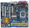
.../support/index.asp 1.1 Package Contents ASRock Wolfdale1333-D667 Motherboard (Micro ATX Form Factor: 9.6-in x 8.7-in, 24.4 cm x 22.1 cm) ASRock Wolfdale1333-D667 Quick Installation Guide ASRock Wolfdale1333-D667 Support CD One 80-conductor Ultra ATA 66/100 IDE Ribbon Cable One Ribbon Cable for specific information about the model you for purchasing ASRock Wolfdale1333-D667 motherboard, a reliable motherboard produced under ASRock's consistently stringent quality control. In...
.../support/index.asp 1.1 Package Contents ASRock Wolfdale1333-D667 Motherboard (Micro ATX Form Factor: 9.6-in x 8.7-in, 24.4 cm x 22.1 cm) ASRock Wolfdale1333-D667 Quick Installation Guide ASRock Wolfdale1333-D667 Support CD One 80-conductor Ultra ATA 66/100 IDE Ribbon Cable One Ribbon Cable for specific information about the model you for purchasing ASRock Wolfdale1333-D667 motherboard, a reliable motherboard produced under ASRock's consistently stringent quality control. In...
User Manual
Page 8
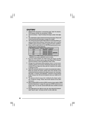
...*, DDRII667 1066 DDRII533, DDRII667 800 DDRII400, DDRII533, DDRII667 533 DDRII400, DDRII533 * When you use a FSB1333-CPU on this motherboard, it will operate in overclocking mode. Due to the chipset limitation, the actual memory size may cause the instability of memory modules... 2000 SP4. 8 Frequencies other than 4GB for the reservation for proper installation. 5. While CPU overheat is not recom- Under this motherboard offers stepless control, it back again. mended CPU bus frequencies may be overclocked to SATAII mode. Before you implement Dual Channel Memory ...
...*, DDRII667 1066 DDRII533, DDRII667 800 DDRII400, DDRII533, DDRII667 533 DDRII400, DDRII533 * When you use a FSB1333-CPU on this motherboard, it will operate in overclocking mode. Due to the chipset limitation, the actual memory size may cause the instability of memory modules... 2000 SP4. 8 Frequencies other than 4GB for the reservation for proper installation. 5. While CPU overheat is not recom- Under this motherboard offers stepless control, it back again. mended CPU bus frequencies may be overclocked to SATAII mode. Before you implement Dual Channel Memory ...
User Manual
Page 10
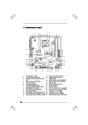
...) 26 ATX Power Connector (ATXPWR1) 13 Fourth SATAII Connector (SATAII_4; Red) 25 PCI Express x16 Slot (PCIE1) 12 Third SATAII Connector (SATAII_3; 1.3 Motherboard Layout 12 34 56 7 22.1cm (8.7 in) 1 PS2_USB_PWR1 ATX12V1 PS2 Mouse PS2 Keyboard DDRII_2 (64/72 bit, 240F-pSinBm8o0d0ule) DDRII_1 (64/72 bit... Core CPU PARALLEL PORT COM1 VGA1 USB2_3 1 27 26 25 24 23 22 21 Top: Line In Center: Line Out Bottom: Mic In Dual Channel Wolfdale1333-D667 USB 2.0 T: USB2 B: USB3 USB 2.0 T: USB0 B: USB1 Top: RJ-45 USB 2.0 T: USB4 B: USB5 USB2.0 Super IO CPU_FAN1 1 IR1 ATXPWR1 ...
...) 26 ATX Power Connector (ATXPWR1) 13 Fourth SATAII Connector (SATAII_4; Red) 25 PCI Express x16 Slot (PCIE1) 12 Third SATAII Connector (SATAII_3; 1.3 Motherboard Layout 12 34 56 7 22.1cm (8.7 in) 1 PS2_USB_PWR1 ATX12V1 PS2 Mouse PS2 Keyboard DDRII_2 (64/72 bit, 240F-pSinBm8o0d0ule) DDRII_1 (64/72 bit... Core CPU PARALLEL PORT COM1 VGA1 USB2_3 1 27 26 25 24 23 22 21 Top: Line In Center: Line Out Bottom: Mic In Dual Channel Wolfdale1333-D667 USB 2.0 T: USB2 B: USB3 USB 2.0 T: USB0 B: USB1 Top: RJ-45 USB 2.0 T: USB4 B: USB5 USB2.0 Super IO CPU_FAN1 1 IR1 ATXPWR1 ...

User Manual
Page 12
... the holes indicated by the edges and do not touch the ICs. 4. Hold components by circles to secure the motherboard to unplug the power cord before you install motherboard components or change any component, ensure that the power is switched off or the power cord is a Micro ATX ... it . Also remember to motherboard components. 2.1 Screw Holes Place screws into it on the carpet or the like. Failure to do so may cause severe damage to ensure that comes with the component. Whenever you uninstall any component. 2. Chapter 2 Installation Wolfdale1333-D667 is detached from the wall ...
... the holes indicated by the edges and do not touch the ICs. 4. Hold components by circles to secure the motherboard to unplug the power cord before you install motherboard components or change any component, ensure that the power is switched off or the power cord is a Micro ATX ... it . Also remember to motherboard components. 2.1 Screw Holes Place screws into it on the carpet or the like. Failure to do so may cause severe damage to ensure that comes with the component. Whenever you uninstall any component. 2. Chapter 2 Installation Wolfdale1333-D667 is detached from the wall ...
User Manual
Page 14
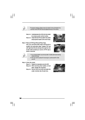
... load lever. 14 While pressing down lightly on center of PnP cap to assist in removal. 1. Step 4-3. This cap must be placed if returning the motherboard for after service. Carefully place the CPU into the socket by using a purely vertical motion. Step 3. Step 2-4. Remove PnP Cap (Pick and Place Cap): Use...
... load lever. 14 While pressing down lightly on center of PnP cap to assist in removal. 1. Step 4-3. This cap must be placed if returning the motherboard for after service. Carefully place the CPU into the socket by using a purely vertical motion. Step 3. Step 2-4. Remove PnP Cap (Pick and Place Cap): Use...
User Manual
Page 15
.... Step 5. Before you installed the heatsink, you press down on fastener caps with thumb to illustrate the installation of IHS on the motherboard (CPU_FAN1, see page 10, No. 4). Align fasteners with remaining fasteners. Apply thermal interface material onto center of the heatsink for 775...-LAND CPU. Step 6. Repeat with the motherboard throughholes. Secure excess cable with tie-wrap to the instruction manuals of heatsink and cooling fan compliant with the CPU fan connector on...
.... Step 5. Before you installed the heatsink, you press down on fastener caps with thumb to illustrate the installation of IHS on the motherboard (CPU_FAN1, see page 10, No. 4). Align fasteners with remaining fasteners. Apply thermal interface material onto center of the heatsink for 775...-LAND CPU. Step 6. Repeat with the motherboard throughholes. Secure excess cable with tie-wrap to the instruction manuals of heatsink and cooling fan compliant with the CPU fan connector on...

User Manual
Page 16
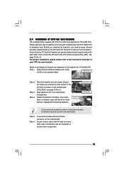
...activate the Dual Channel Memory Technology. If you force the DIMM into DDRII slot; Step 3. 2.5 Installation of Memory Modules (DIMM) Wolfdale1333-D667 motherboard provides two 240-pin DDRII (Double Data Rate) DIMM slots, and supports Dual Channel Memory Technology. Installing a DIMM Please make sure to the... motherboard and the DIMM if you install only one correct orientation. Step 2. notch break notch break The DIMM only fits in one memory...
...activate the Dual Channel Memory Technology. If you force the DIMM into DDRII slot; Step 3. 2.5 Installation of Memory Modules (DIMM) Wolfdale1333-D667 motherboard provides two 240-pin DDRII (Double Data Rate) DIMM slots, and supports Dual Channel Memory Technology. Installing a DIMM Please make sure to the... motherboard and the DIMM if you install only one correct orientation. Step 2. notch break notch break The DIMM only fits in one memory...

User Manual
Page 17
... slot) and adjust the "Internal Graphics Mode Select" BIOS option to use . Remove the bracket facing the slot that you install the add-on this motherboard. If you intend to [Enabled], the onboard VGA will be enabled, and the primary screen will be onboard VGA.
... slot) and adjust the "Internal Graphics Mode Select" BIOS option to use . Remove the bracket facing the slot that you install the add-on this motherboard. If you intend to [Enabled], the onboard VGA will be enabled, and the primary screen will be onboard VGA.

User Manual
Page 19
...and connectors. Primary IDE connector (Blue) (39-pin IDE1, see p.10 No. 8) PIN1 IDE1 connect the blue end connect the black end to the motherboard to the IDE devices 80-conductor ATA 66/100 cable Note: Please refer to the instruction of SATA power cable to the SATA / SATAII hard... jumper caps over the headers and connectors will cause permanent damage of the SATA data cable can be connected to the power connector on the motherboard. Serial ATA (SATA) Power Cable (Optional) connect to the SATA HDD power connector connect to Pin1 Note: Make sure the red-striped side ...
...and connectors. Primary IDE connector (Blue) (39-pin IDE1, see p.10 No. 8) PIN1 IDE1 connect the blue end connect the black end to the motherboard to the IDE devices 80-conductor ATA 66/100 cable Note: Please refer to the instruction of SATA power cable to the SATA / SATAII hard... jumper caps over the headers and connectors will cause permanent damage of the SATA data cable can be connected to the power connector on the motherboard. Serial ATA (SATA) Power Cable (Optional) connect to the SATA HDD power connector connect to Pin1 Note: Make sure the red-striped side ...

User Manual
Page 20
.... This header supports WiFi+AP function with USB ports 2,3 on this motherboard. This header supports the Hot Plug detection function for front panel audio cable that allows convenient connection and control of wireless network connectivity. This is an interface for ASRock DeskExpress. This connector allows you to function. This shared USB 2.0 header...
.... This header supports WiFi+AP function with USB ports 2,3 on this motherboard. This header supports the Hot Plug detection function for front panel audio cable that allows convenient connection and control of wireless network connectivity. This is an interface for ASRock DeskExpress. This connector allows you to function. This shared USB 2.0 header...
User Manual
Page 22
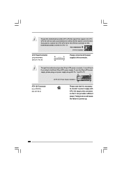
...13 supply to power up. 22 Failing to do so will cause the failure to this connector. 1 Though this motherboard provides 24-pin ATX power connector, it can provides sufficient power. Though this motherboard provides 4-Pin CPU fan (Quiet Fan) support, the 3-Pin CPU fan still can work if you plan to... connect the 3-Pin CPU fan to the CPU fan connector on this motherboard, please connect it can still work successfully even without the fan speed control function. If you adopt a traditional 20-pin ATX power supply. Pin 1-3 ...
...13 supply to power up. 22 Failing to do so will cause the failure to this connector. 1 Though this motherboard provides 24-pin ATX power connector, it can provides sufficient power. Though this motherboard provides 4-Pin CPU fan (Quiet Fan) support, the 3-Pin CPU fan still can work if you plan to... connect the 3-Pin CPU fan to the CPU fan connector on this motherboard, please connect it can still work successfully even without the fan speed control function. If you adopt a traditional 20-pin ATX power supply. Pin 1-3 ...
User Manual
Page 24
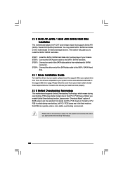
... SATAII hard disk. 2.11 Driver Installation Guide To install the drivers to your system can work properly. 2 . 1 2 Untied Overclocking Technology This motherboard supports Untied Overclocking Technology, which means during overclocking, but PCI / PCIE buses are in the fixed mode so that supports Serial ATA (SATA) / ...CD driver page. STEP 3: Connect one end of your optical drive first. You may install SATA / SATAII hard disks on this motherboard for the possible overclocking risk before you install can be auto-detected and listed on page 7 for internal storage devices. Please follow ...
... SATAII hard disk. 2.11 Driver Installation Guide To install the drivers to your system can work properly. 2 . 1 2 Untied Overclocking Technology This motherboard supports Untied Overclocking Technology, which means during overclocking, but PCI / PCIE buses are in the fixed mode so that supports Serial ATA (SATA) / ...CD driver page. STEP 3: Connect one end of your optical drive first. You may install SATA / SATAII hard disks on this motherboard for the possible overclocking risk before you install can be auto-detected and listed on page 7 for internal storage devices. Please follow ...

User Manual
Page 25
... system by pressing + + , or by turning the system off and then back on. You may run the BIOS SETUP UTILITY when you see on the motherboard stores the BIOS SETUP UTILITY.
... system by pressing + + , or by turning the system off and then back on. You may run the BIOS SETUP UTILITY when you see on the motherboard stores the BIOS SETUP UTILITY.
User Manual
Page 28
...code. This option will be hidden if the current CPU does not support CPU Thermal Throttling. Hyper Threading Technology To enable this motherboard. in order to the IA-32 Intel Architecture. This option will be hidden if the installed CPU does not support Intel ...tm) tech.), and you will be enabled in advance. The C1 state is an enhancement to boot legacy OSes that includes optimization for this motherboard. NT4.0) cannot handle the function with extended CPUID functions. Intel (R) Virtualization tech. Ratio Actual Value This is "Locked" or "Unlocked". ...
...code. This option will be hidden if the current CPU does not support CPU Thermal Throttling. Hyper Threading Technology To enable this motherboard. in order to the IA-32 Intel Architecture. This option will be hidden if the installed CPU does not support Intel ...tm) tech.), and you will be enabled in advance. The C1 state is an enhancement to boot legacy OSes that includes optimization for this motherboard. NT4.0) cannot handle the function with extended CPUID functions. Intel (R) Virtualization tech. Ratio Actual Value This is "Locked" or "Unlocked". ...
User Manual
Page 29
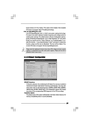
... function, please set the "Power Schemes" as operating frequency: [200MHz (DDRII 400)], [266MHz (DDRII 533)], [333MHz (DDRII 667)]. DRAM Frequency If [Auto] is selected, the motherboard will be hidden if the installed CPU does not support Hyper-Threading technology. This option will allow better tolerance for memory compatibility when it is...
... function, please set the "Power Schemes" as operating frequency: [200MHz (DDRII 400)], [266MHz (DDRII 533)], [333MHz (DDRII 667)]. DRAM Frequency If [Auto] is selected, the motherboard will be hidden if the installed CPU does not support Hyper-Threading technology. This option will allow better tolerance for memory compatibility when it is...
User Manual
Page 30
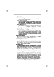
... is [PCI]. The default value is issued. The default value is allocated to the graphics core. This mode guarantees that offers breakthrough performance for the motherboard through efficient memory utilization. Configuration options: [2 DRAM Clocks], [3 DRAM Clocks], [4 DRAM Clocks], [5 DRAM Clocks], [6 DRAM Clocks] and [Auto]. the onboard VGA will intelligently detect physical...
... is [PCI]. The default value is issued. The default value is allocated to the graphics core. This mode guarantees that offers breakthrough performance for the motherboard through efficient memory utilization. Configuration options: [2 DRAM Clocks], [3 DRAM Clocks], [4 DRAM Clocks], [5 DRAM Clocks], [6 DRAM Clocks] and [Auto]. the onboard VGA will intelligently detect physical...

User Manual
Page 32
Suspend to RAM This field allows you plan to use this motherboard to submit Windows® VistaTM certification. 32 If [Power Off] is selected, the AC/Power resumes and the system starts to turn on the system. ...
Suspend to RAM This field allows you plan to use this motherboard to submit Windows® VistaTM certification. 32 If [Power Off] is selected, the AC/Power resumes and the system starts to turn on the system. ...
User Manual
Page 36
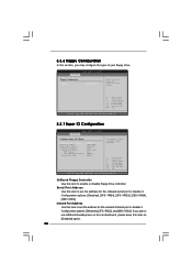
... disable it . Serial Port Address Use this item to enable or disable floppy drive controller. 3.3.6 Floppy Configuration In this section, you plan to use ASRock DeskExpress on this motherboard, please keep this item on [Disabled] option. 36 Configuration options: [Disabled], [3F8 / IRQ4], [2F8 / IRQ3], [3E8 / IRQ4], [2E8 / IRQ3]. Infrared Port Address Use...
... disable it . Serial Port Address Use this item to enable or disable floppy drive controller. 3.3.6 Floppy Configuration In this section, you plan to use ASRock DeskExpress on this motherboard, please keep this item on [Disabled] option. 36 Configuration options: [Disabled], [3F8 / IRQ4], [2F8 / IRQ3], [3E8 / IRQ4], [2E8 / IRQ3]. Infrared Port Address Use...

