User Manual
Page 2
...conditions: (1) this device may appear in the documentation or product. "Perchlorate Material-special handling may cause undesired operation. ASRock assumes no event shall ASRock, its directors, officers, employees, or agents be registered trademarks or copyrights of HDMI Licensing LLC in advance. This ... business, loss of data, interruption of business and the like), even if ASRock has been advised of the possibility of such damages arising from any defect or error in this motherboard contains Perchlorate, a toxic substance controlled in any form or by the California Legislature...
...conditions: (1) this device may appear in the documentation or product. "Perchlorate Material-special handling may cause undesired operation. ASRock assumes no event shall ASRock, its directors, officers, employees, or agents be registered trademarks or copyrights of HDMI Licensing LLC in advance. This ... business, loss of data, interruption of business and the like), even if ASRock has been advised of the possibility of such damages arising from any defect or error in this motherboard contains Perchlorate, a toxic substance controlled in any form or by the California Legislature...
User Manual
Page 3
Contents Chapter 1 Introduction 1 1.1 Package Contents 1 1.2 Specifications 2 1.3 Motherboard Layout 6 1.4 I/O Panel 8 Chapter 2 Installation 9 2.1 Installing Memory Modules (SO-DIMM) 10 2.2 Expansion Slots (PCI Express Slots) 12 2.5 Jumpers Setup 13 2.6 Onboard Headers and Connectors 14 Chapter 3 Software and Utilities Operation 20 3.1 Installing Drivers 20 3.2 A-Tuning 21 3.3 Intel® Smart Connect Technology 23 3.5 ASRock Cloud 28 3.6 ASRock APP Shop 37 3.6.1 UI Overview 37 3.6.2 Apps 38 3.6.3 BIOS & Drivers 41 3.6.4 Setting 42 3.7 Start8 44
Contents Chapter 1 Introduction 1 1.1 Package Contents 1 1.2 Specifications 2 1.3 Motherboard Layout 6 1.4 I/O Panel 8 Chapter 2 Installation 9 2.1 Installing Memory Modules (SO-DIMM) 10 2.2 Expansion Slots (PCI Express Slots) 12 2.5 Jumpers Setup 13 2.6 Onboard Headers and Connectors 14 Chapter 3 Software and Utilities Operation 20 3.1 Installing Drivers 20 3.2 A-Tuning 21 3.3 Intel® Smart Connect Technology 23 3.5 ASRock Cloud 28 3.6 ASRock APP Shop 37 3.6.1 UI Overview 37 3.6.2 Apps 38 3.6.3 BIOS & Drivers 41 3.6.4 Setting 42 3.7 Start8 44
User Manual
Page 5
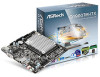
... be available on ASRock's website as well. ASRock website http://www.asrock.com. 1.1 Package Contents • ASRock Q1900TM-ITX Motherboard (Mini-ITX Form Factor) • ASRock Q1900TM-ITX Quick Installation Guide • ASRock Q1900TM-ITX Support CD • 2 x Serial ATA (SATA) Data Cables (Optional) • 1 x SATA 1 to quality and endurance. In this motherboard, please visit our website for purchasing ASRock Q1900TM-ITX motherboard, a reliable motherboard produced under ASRock's consistently stringent quality...
... be available on ASRock's website as well. ASRock website http://www.asrock.com. 1.1 Package Contents • ASRock Q1900TM-ITX Motherboard (Mini-ITX Form Factor) • ASRock Q1900TM-ITX Quick Installation Guide • ASRock Q1900TM-ITX Support CD • 2 x Serial ATA (SATA) Data Cables (Optional) • 1 x SATA 1 to quality and endurance. In this motherboard, please visit our website for purchasing ASRock Q1900TM-ITX motherboard, a reliable motherboard produced under ASRock's consistently stringent quality...
User Manual
Page 13
Failure to do so may damage the motherboard. 9 English Q1900TM-ITX Chapter 2 Installation This is an Mini-ITX form factor motherboard. Also remember to the motherboard's components, NEVER place your chassis to ensure that comes with the components. • When placing screws to secure the motherboard to the chassis, please do not touch the ICs. • Whenever you...
Failure to do so may damage the motherboard. 9 English Q1900TM-ITX Chapter 2 Installation This is an Mini-ITX form factor motherboard. Also remember to the motherboard's components, NEVER place your chassis to ensure that comes with the components. • When placing screws to secure the motherboard to the chassis, please do not touch the ICs. • Whenever you...

User Manual
Page 14
otherwise, this motherboard and SO-DIMM may be damaged. Please install the SO-DIMM module into the slot at incorrect orientation. 10 English The SO-DIMM only fits in one correct orientation. 2.1 Installing Memory Modules (SO-DIMM) This motherboard provides two 204-pin DDR3/DDR3L (Double Data Rate 3) SODIMM slots. It will cause permanent damage to install a DDR or DDR2 memory module into a DDR3/DDR3L slot; It is not allowed to the motherboard and the SO-DIMM if you force the SO-DIMM into the DDR3_A1 for the first priority.
otherwise, this motherboard and SO-DIMM may be damaged. Please install the SO-DIMM module into the slot at incorrect orientation. 10 English The SO-DIMM only fits in one correct orientation. 2.1 Installing Memory Modules (SO-DIMM) This motherboard provides two 204-pin DDR3/DDR3L (Double Data Rate 3) SODIMM slots. It will cause permanent damage to install a DDR or DDR2 memory module into a DDR3/DDR3L slot; It is not allowed to the motherboard and the SO-DIMM if you force the SO-DIMM into the DDR3_A1 for the first priority.

User Manual
Page 16
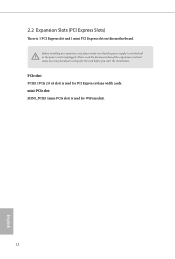
Please read the documentation of the expansion card and make sure that the power supply is switched off or the power cord is used for WiFi module. 12 English mini-PCIe slot: MINI_PCIE1 (mini-PCIe slot) is 1 PCI Express slot and 1 mini PCI Express slot on this motherboard. 2.2 Expansion Slots (PCI Express Slots) There is used for the card before you start the installation. PCIe slot: PCIE1 (PCIe 2.0 x4 slot) is unplugged. Before installing an expansion card, please make necessary hardware settings for PCI Express x4 lane width cards.
Please read the documentation of the expansion card and make sure that the power supply is switched off or the power cord is used for WiFi module. 12 English mini-PCIe slot: MINI_PCIE1 (mini-PCIe slot) is 1 PCI Express slot and 1 mini PCI Express slot on this motherboard. 2.2 Expansion Slots (PCI Express Slots) There is used for the card before you start the installation. PCIe slot: PCIE1 (PCIe 2.0 x4 slot) is unplugged. Before installing an expansion card, please make necessary hardware settings for PCI Express x4 lane width cards.
User Manual
Page 18
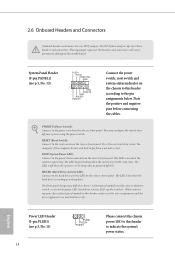
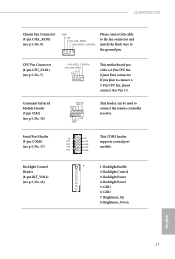
... LED is off when the system is in S4 sleep state or powered off your chassis front panel module to this header according to the motherboard. A front panel module mainly consists of power switch, reset switch, power LED, hard drive activity LED, speaker and etc. English Power LED Header (3-pin PLED1...
... LED is off when the system is in S4 sleep state or powered off your chassis front panel module to this header according to the motherboard. A front panel module mainly consists of power switch, reset switch, power LED, hard drive activity LED, speaker and etc. English Power LED Header (3-pin PLED1...
User Manual
Page 19
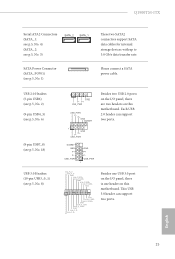
... IntA_P_DGND IntA_P_SSTX+ IntA_P_SSTXGND IntA_P_SSRX+ IntA_P_SSRXVbus 1 Vbus IntA_P_SSRXIntA_P_SSRX+ GND IntA_P_SSTXIntA_P_SSTX+ GND IntA_P_DIntA_P_D+ ID Besides one USB 3.0 port on the I /O panel, there are two headers on this motherboard. Q1900TM-ITX Serial ATA2 Connectors (SATA_1: see p.5, No. 4) (SATA_2: see p.5, No. 3) SATA_2 SATA_1 SATA Power Connector (SATA_POW1) (see p.5, No. 8) 1 GND P- USB ... PP+ GND DUMMY Besides two USB 2.0 ports on the I /O panel, there is one header on this motherboard. This USB 3.0 header can support two ports. 1 GND P+ PUSB_PWR DUMMY GND P+ P-
... IntA_P_DGND IntA_P_SSTX+ IntA_P_SSTXGND IntA_P_SSRX+ IntA_P_SSRXVbus 1 Vbus IntA_P_SSRXIntA_P_SSRX+ GND IntA_P_SSTXIntA_P_SSTX+ GND IntA_P_DIntA_P_D+ ID Besides one USB 3.0 port on the I /O panel, there are two headers on this motherboard. Q1900TM-ITX Serial ATA2 Connectors (SATA_1: see p.5, No. 4) (SATA_2: see p.5, No. 3) SATA_2 SATA_1 SATA Power Connector (SATA_POW1) (see p.5, No. 8) 1 GND P- USB ... PP+ GND DUMMY Besides two USB 2.0 ports on the I /O panel, there is one header on this motherboard. This USB 3.0 header can support two ports. 1 GND P+ PUSB_PWR DUMMY GND P+ P-
User Manual
Page 21
.... Serial Port Header (9-pin COM1) (see p.5, No. 17) Backlight Control Header (8-pin BLT_VOL1) (see p.5, No. 10) FAN_SPEED_CONTROL CPU_FAN_SPEED +12V GND This motherboard provides a 4-Pin CPU fan (Quiet Fan) connector. Q1900TM-ITX Chassis Fan Connector (4-pin CHA_FAN1) (see p.5, No. 9) GND +12V CHA_FAN_SPEED FAN_SPEED_CONTROL Please connect fan cable to the fan connector and match the...
.... Serial Port Header (9-pin COM1) (see p.5, No. 17) Backlight Control Header (8-pin BLT_VOL1) (see p.5, No. 10) FAN_SPEED_CONTROL CPU_FAN_SPEED +12V GND This motherboard provides a 4-Pin CPU fan (Quiet Fan) connector. Q1900TM-ITX Chassis Fan Connector (4-pin CHA_FAN1) (see p.5, No. 9) GND +12V CHA_FAN_SPEED FAN_SPEED_CONTROL Please connect fan cable to the fan connector and match the...
User Manual
Page 24
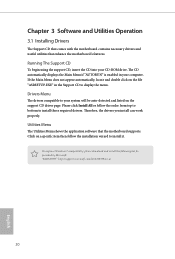
Utilities Menu The Utilities Menu shows the application software that enhance the motherboard's features. Click on a specific item then follow the order from top to bottom to your system will be auto-detected and listed on the file "... Install All or follow the installation wizard to display the menu. Chapter 3 Software and Utilities Operation 3.1 Installing Drivers The Support CD that comes with the motherboard contains necessary drivers and useful utilities that the...
Utilities Menu The Utilities Menu shows the application software that enhance the motherboard's features. Click on a specific item then follow the order from top to bottom to your system will be auto-detected and listed on the file "... Install All or follow the installation wizard to display the menu. Chapter 3 Software and Utilities Operation 3.1 Installing Drivers The Support CD that comes with the motherboard contains necessary drivers and useful utilities that the...
User Manual
Page 27
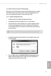
... change the value from Windows® sleep state to -date. 3.3.1 System Requirements • Confirm whether your motherboard supports this feature. • Operating system: Microsoft Windows 8/7 (32- If Windows 8/7 is not in Windows Registry Editor. Q1900TM-ITX 3.3 Intel® Smart Connect Technology Intel® Smart Connect Technology is a feature that periodically wakes your computer...
... change the value from Windows® sleep state to -date. 3.3.1 System Requirements • Confirm whether your motherboard supports this feature. • Operating system: Microsoft Windows 8/7 (32- If Windows 8/7 is not in Windows Registry Editor. Q1900TM-ITX 3.3 Intel® Smart Connect Technology Intel® Smart Connect Technology is a feature that periodically wakes your computer...
User Manual
Page 32
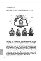
... remote desktop application. Have you ever been in a situation where you can connect with your PC from anywhere in the world. This motherboard supports Security Wake On Internet Technology with the onboard Qualcomm® Atheros® AR8171, so you emergently needed certain files in off ,... monitor and take control of reach? For ASRock motherboards with a Qualcomm® Atheros® AR8171 LAN chip, ASRock Cloud allows users to remotely wake up their computers, or they could wake up the computer then use Orbweb.ME...
... remote desktop application. Have you ever been in a situation where you can connect with your PC from anywhere in the world. This motherboard supports Security Wake On Internet Technology with the onboard Qualcomm® Atheros® AR8171, so you emergently needed certain files in off ,... monitor and take control of reach? For ASRock motherboards with a Qualcomm® Atheros® AR8171 LAN chip, ASRock Cloud allows users to remotely wake up their computers, or they could wake up the computer then use Orbweb.ME...
User Manual
Page 36
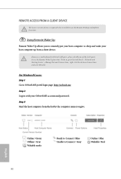
... name you to remotely put your Orbweb.ME account and password. If you use the Remote Wake-Up function. To do so, go to use a motherboard with your host computer to use the Remote Desktop and Xplorer functions. REMOTE ACCESS FROM A CLIENT DEVICE The lastest version of the LAN ports to...
... name you to remotely put your Orbweb.ME account and password. If you use the Remote Wake-Up function. To do so, go to use a motherboard with your host computer to use the Remote Desktop and Xplorer functions. REMOTE ACCESS FROM A CLIENT DEVICE The lastest version of the LAN ports to...
User Manual
Page 41
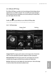
... news. Double-click on the image to date simply with a few clicks. Q1900TM-ITX 3.6 ASRock APP Shop The ASRock APP Shop is an online store for purchasing and downloading software applications for your desktop to access ASRock APP Shop utility. *You need to be connected to the Internet to perform ...job-related tasks. You can install various apps and support utilities quickly and easily, and optimize your system and keep your motherboard up to visit the website ...
... news. Double-click on the image to date simply with a few clicks. Q1900TM-ITX 3.6 ASRock APP Shop The ASRock APP Shop is an online store for purchasing and downloading software applications for your desktop to access ASRock APP Shop utility. *You need to be connected to the Internet to perform ...job-related tasks. You can install various apps and support utilities quickly and easily, and optimize your system and keep your motherboard up to visit the website ...

User Manual
Page 67
... Customize to monitor the status of the hardware on your system, including the parameters of the CPU temperature, motherboard temperature, fan speed and voltage. CPU Fan 1 Type Select 3pin or 4pin fan type. Q1900TM-ITX 4.5 Hardware Health Event Monitoring Screen This section allows you to set CPU temperatures and assign a respective fan speed...
... Customize to monitor the status of the hardware on your system, including the parameters of the CPU temperature, motherboard temperature, fan speed and voltage. CPU Fan 1 Type Select 3pin or 4pin fan type. Q1900TM-ITX 4.5 Hardware Health Event Monitoring Screen This section allows you to set CPU temperatures and assign a respective fan speed...

Quick Installation Guide
Page 1
... such damages arising from any interference received, including interference that may appear in Perchlorate Best Management Practices (BMP) regulations passed by ASRock. This device complies with Part 15 of this motherboard contains Perchlorate, a toxic substance controlled in this documentation may cause undesired operation. In no responsibility for a particular purpose. CALIFORNIA, USA ONLY...
... such damages arising from any interference received, including interference that may appear in Perchlorate Best Management Practices (BMP) regulations passed by ASRock. This device complies with Part 15 of this motherboard contains Perchlorate, a toxic substance controlled in this documentation may cause undesired operation. In no responsibility for a particular purpose. CALIFORNIA, USA ONLY...
Quick Installation Guide
Page 5
Failure to do so may damage the motherboard. 4 English Chapter 2 Installation This is an Mini-ITX form factor motherboard. Also remember to unplug the power cord before you install motherboard components or change any components, place them on a carpet. Pre-installation Precautions Take note of your motherboard directly on a grounded anti-static pad or in the...
Failure to do so may damage the motherboard. 4 English Chapter 2 Installation This is an Mini-ITX form factor motherboard. Also remember to unplug the power cord before you install motherboard components or change any components, place them on a carpet. Pre-installation Precautions Take note of your motherboard directly on a grounded anti-static pad or in the...
Quick Installation Guide
Page 6
...; ASRock Q1900TM-ITX Motherboard (Mini-ITX Form Factor) • ASRock Q1900TM-ITX Quick Installation Guide • ASRock Q1900TM-ITX Support CD • 2 x Serial ATA (SATA) Data Cables (Optional) • 1 x SATA 1 to quality and endurance. Because the motherboard specifications and the BIOS software might be updated, the content of this motherboard, please visit our website for specific information about the model you for purchasing ASRock Q1900TM-ITX motherboard...
...; ASRock Q1900TM-ITX Motherboard (Mini-ITX Form Factor) • ASRock Q1900TM-ITX Quick Installation Guide • ASRock Q1900TM-ITX Support CD • 2 x Serial ATA (SATA) Data Cables (Optional) • 1 x SATA 1 to quality and endurance. Because the motherboard specifications and the BIOS software might be updated, the content of this motherboard, please visit our website for specific information about the model you for purchasing ASRock Q1900TM-ITX motherboard...
Quick Installation Guide
Page 11
It is not allowed to the motherboard and the SO-DIMM if you force the SO-DIMM into a DDR3/DDR3L slot; It will cause permanent damage to install a DDR or DDR2 memory module into the slot at incorrect orientation. 10 English The SO-DIMM only fits in one correct orientation. 2.1 Installing Memory Modules (SO-DIMM) This motherboard provides two 204-pin DDR3/DDR3L (Double Data Rate 3) SODIMM slots. otherwise, this motherboard and SO-DIMM may be damaged. Please install the SO-DIMM module into the DDR3_A1 for the first priority.
It is not allowed to the motherboard and the SO-DIMM if you force the SO-DIMM into a DDR3/DDR3L slot; It will cause permanent damage to install a DDR or DDR2 memory module into the slot at incorrect orientation. 10 English The SO-DIMM only fits in one correct orientation. 2.1 Installing Memory Modules (SO-DIMM) This motherboard provides two 204-pin DDR3/DDR3L (Double Data Rate 3) SODIMM slots. otherwise, this motherboard and SO-DIMM may be damaged. Please install the SO-DIMM module into the DDR3_A1 for the first priority.
Quick Installation Guide
Page 13
Please read the documentation of the expansion card and make sure that the power supply is switched off or the power cord is 1 PCI Express slot and 1 mini PCI Express slot on this motherboard. mini-PCIe slot: MINI_PCIE1 (mini-PCIe slot) is used for WiFi module. 12 English PCIe slot: PCIE1 (PCIe 2.0 x4 slot) is used for the card before you start the installation. 2.2 Expansion Slots (PCI Express Slots) There is unplugged. Before installing an expansion card, please make necessary hardware settings for PCI Express x4 lane width cards.
Please read the documentation of the expansion card and make sure that the power supply is switched off or the power cord is 1 PCI Express slot and 1 mini PCI Express slot on this motherboard. mini-PCIe slot: MINI_PCIE1 (mini-PCIe slot) is used for WiFi module. 12 English PCIe slot: PCIE1 (PCIe 2.0 x4 slot) is used for the card before you start the installation. 2.2 Expansion Slots (PCI Express Slots) There is unplugged. Before installing an expansion card, please make necessary hardware settings for PCI Express x4 lane width cards.

