RAID Installation Guide
Page 2
... disks on SATA ports. 2 1. This section will guide you how to create RAID on this guide carefully according to the Intel southbridge chipset that your motherboard adopts. Please read the RAID configurations in the support CD. For SATA installation guide, please refer to SATA Hard Disks Installation 1.1 Serial ATA (SATA) Hard...
... disks on SATA ports. 2 1. This section will guide you how to create RAID on this guide carefully according to the Intel southbridge chipset that your motherboard adopts. Please read the RAID configurations in the support CD. For SATA installation guide, please refer to SATA Hard Disks Installation 1.1 Serial ATA (SATA) Hard...
RAID Installation Guide
Page 3
.... 2. Guide to RAID Configurations 2.1 Introduction of the same model and capacity when creating a RAID set. For optimal performance, please install identical drives of RAID This motherboard adopts Intel southbridge chipset that integrates RAID controller supporting RAID 0 / RAID 1/ Intel Matrix Storage / RAID 10 / RAID 5 function with six independent Serial ATA (SATA) channels...
.... 2. Guide to RAID Configurations 2.1 Introduction of the same model and capacity when creating a RAID set. For optimal performance, please install identical drives of RAID This motherboard adopts Intel southbridge chipset that integrates RAID controller supporting RAID 0 / RAID 1/ Intel Matrix Storage / RAID 10 / RAID 5 function with six independent Serial ATA (SATA) channels...

RAID Installation Guide
Page 8
.../ICH10R/DO/PCH SATA RAID Controller - You may also use this , you install. Windows XP64". 5. This will need another SATA / SATAII hard drive with your motherboard or after downloading it as prompted. Windows XP/2000" or "Intel(R) ICH8R/ICH9R/ICH10R/DO/PCH SATA RAID Controller - you will use third-party software...
.../ICH10R/DO/PCH SATA RAID Controller - You may also use this , you install. Windows XP64". 5. This will need another SATA / SATAII hard drive with your motherboard or after downloading it as prompted. Windows XP/2000" or "Intel(R) ICH8R/ICH9R/ICH10R/DO/PCH SATA RAID Controller - you will use third-party software...

User Manual
Page 2
... may not be liable for identification or explanation and to infringe. Operation is subject to the implied warranties or conditions of ASRock Inc. Disclaimer: Specifications and information contained in this motherboard contains Perchlorate, a toxic substance controlled in the manual or product. CALIFORNIA, USA ONLY The Lithium battery adopted on this manual are...
... may not be liable for identification or explanation and to infringe. Operation is subject to the implied warranties or conditions of ASRock Inc. Disclaimer: Specifications and information contained in this motherboard contains Perchlorate, a toxic substance controlled in the manual or product. CALIFORNIA, USA ONLY The Lithium battery adopted on this manual are...

User Manual
Page 3
... 1 Introduction 5 1.1 Package Contents 5 1.2 Specifications 6 1.3 Two SLITM Graphics Card Support List 10 1.4 Two CrossFireXTM Graphics Card Support List 11 1.5 Three CrossFireXTM Graphics Card Support List .......... 11 1.6 Motherboard Layout 12 1.7 I/O Panel 13 2 Installation 14 2.1 Screw Holes 14 2.2 Pre-installation Precautions 14 2.3 CPU Installation 15 2.4 Installation of Heatsink and CPU fan 17 2.5 Installation of...
... 1 Introduction 5 1.1 Package Contents 5 1.2 Specifications 6 1.3 Two SLITM Graphics Card Support List 10 1.4 Two CrossFireXTM Graphics Card Support List 11 1.5 Three CrossFireXTM Graphics Card Support List .......... 11 1.6 Motherboard Layout 12 1.7 I/O Panel 13 2 Installation 14 2.1 Screw Holes 14 2.2 Pre-installation Precautions 14 2.3 CPU Installation 15 2.4 Installation of Heatsink and CPU fan 17 2.5 Installation of...

User Manual
Page 5
..., chapter 1 and 2 contain introduction of the Support CD. In case any modifications of this manual will be subject to change without further notice. ASRock website http://www.asrock.com If you for purchasing ASRock P55 Extreme motherboard, a reliable motherboard produced under ASRock's consistently stringent quality control. You may find the latest VGA cards and CPU support lists on...
..., chapter 1 and 2 contain introduction of the Support CD. In case any modifications of this manual will be subject to change without further notice. ASRock website http://www.asrock.com If you for purchasing ASRock P55 Extreme motherboard, a reliable motherboard produced under ASRock's consistently stringent quality control. You may find the latest VGA cards and CPU support lists on...

User Manual
Page 8
.... CAUTION! 1. Due to the components and devices of "Hyper Threading Technology", please check page 60. 2. For audio output, this motherboard supports both stereo and mono modes. Chassis Temperature Sensing - Overclocking may be done at your system stability, or even cause damage to ...the operating system limitation, the actual memory size may affect your own risk and expense. ASRock U-COP (see CAUTION 15) * For detailed product information, please visit our website: http://www.asrock.com WARNING Please realize that only support up to read "Untied Overclocking Technology" on ...
.... CAUTION! 1. Due to the components and devices of "Hyper Threading Technology", please check page 60. 2. For audio output, this motherboard supports both stereo and mono modes. Chassis Temperature Sensing - Overclocking may be done at your system stability, or even cause damage to ...the operating system limitation, the actual memory size may affect your own risk and expense. ASRock U-COP (see CAUTION 15) * For detailed product information, please visit our website: http://www.asrock.com WARNING Please realize that only support up to read "Untied Overclocking Technology" on ...

User Manual
Page 9
...® environment. Frequencies other words, it is not recommended to access ASRock Instant Flash. Please be noticed that delivers unparalleled power savings. To meet EuP standard, an EuP ready motherboard and an EuP ready power supply are required. 7. ASRock website: http://www.asrock.com/feature/OCTuner/index.htm 10. Before installing SATAII hard disk...
...® environment. Frequencies other words, it is not recommended to access ASRock Instant Flash. Please be noticed that delivers unparalleled power savings. To meet EuP standard, an EuP ready motherboard and an EuP ready power supply are required. 7. ASRock website: http://www.asrock.com/feature/OCTuner/index.htm 10. Before installing SATAII hard disk...

User Manual
Page 12
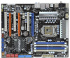
1.6 Motherboard Layout 12 24.4cm (9.6 in) PS2 Mouse PS2 Keyboard 1 ATX12V1 PS2_USB_PWR1 34 56 RSTBTN... PWR_FAN1 CHA_FAN3 Top: LINE IN Center: FRONT Bottom: MIC IN 40 LAN PHY CPU_FAN1 P55 Extreme 39 PCIE1 38 PCI1 VIA VT6330 16Mb BIOS 37 CMOS CrossFireX Battery PCIE2 36 1394a Intel Super I/O PCIE3 PCI Express...22 Dr. Debug (LED) 2 ATX 12V Power Connector (ATX12V1) 23 USB 2.0 Header (USB8_9, Blue) 3 1156-Pin CPU Socket 24 Intel P55 Chipset 4 Chassis Fan Connector (CHA_FAN3) 25 Front Panel IEEE 1394 Header 5 2 x 240-pin DDR3 DIMM Slots (FRONT_1394, Red) (Dual ...
1.6 Motherboard Layout 12 24.4cm (9.6 in) PS2 Mouse PS2 Keyboard 1 ATX12V1 PS2_USB_PWR1 34 56 RSTBTN... PWR_FAN1 CHA_FAN3 Top: LINE IN Center: FRONT Bottom: MIC IN 40 LAN PHY CPU_FAN1 P55 Extreme 39 PCIE1 38 PCI1 VIA VT6330 16Mb BIOS 37 CMOS CrossFireX Battery PCIE2 36 1394a Intel Super I/O PCIE3 PCI Express...22 Dr. Debug (LED) 2 ATX 12V Power Connector (ATX12V1) 23 USB 2.0 Header (USB8_9, Blue) 3 1156-Pin CPU Socket 24 Intel P55 Chipset 4 Chassis Fan Connector (CHA_FAN3) 25 Front Panel IEEE 1394 Header 5 2 x 240-pin DDR3 DIMM Slots (FRONT_1394, Red) (Dual ...

User Manual
Page 14
... indicated by the edges and do so may cause physical injuries to you and damages to motherboard components. 2.1 Screw Holes Place screws into it. Hold components by circles to secure the motherboard to use a grounded wrist strap or touch a safety grounded object before you uninstall any ...it on the carpet or the like. Also remember to the chassis. Do not over-tighten the screws! Whenever you install motherboard components or change any motherboard settings. 1. Make sure to ensure that comes with the component. Unplug the power cord from the power supply. Before you ...
... indicated by the edges and do so may cause physical injuries to you and damages to motherboard components. 2.1 Screw Holes Place screws into it. Hold components by circles to secure the motherboard to use a grounded wrist strap or touch a safety grounded object before you uninstall any ...it on the carpet or the like. Also remember to the chassis. Do not over-tighten the screws! Whenever you install motherboard components or change any motherboard settings. 1. Make sure to ensure that comes with the component. Unplug the power cord from the power supply. Before you ...

User Manual
Page 15
... cap. 2. Step 2. Step 1-2. Remove PnP Cap (Pick and Place Cap). 1. This cap must be seriously damaged. Otherwise, the CPU will be placed if returning the motherboard for after service. 15 Open the socket: Step 1-1. Disengaging the lever by depressing down and out on the socket. Load Plate Load Lever Contact Array...
... cap. 2. Step 2. Step 1-2. Remove PnP Cap (Pick and Place Cap). 1. This cap must be seriously damaged. Otherwise, the CPU will be placed if returning the motherboard for after service. 15 Open the socket: Step 1-1. Disengaging the lever by depressing down and out on the socket. Load Plate Load Lever Contact Array...

User Manual
Page 17
... with remaining fasteners. Then connect the CPU fan to the CPU_FAN connector (CPU_FAN1, see page 12, No. 40). Repeat with the motherboard throughholes. Step 6. Secure excess cable with tie-wrap to ensure cable does not interfere with Intel 1156-Pin CPU to dissipate heat. Apply...heatsink are securely fastened and in good contact with thumb to install and lock. Step 3. 2.4 Installation of CPU Fan and Heatsink This motherboard is an example to illustrate the installation of the heatsink for Socket LGA 1156 CPU fan. 17 Ensure fan cables are for 1156-...
... with remaining fasteners. Then connect the CPU fan to the CPU_FAN connector (CPU_FAN1, see page 12, No. 40). Repeat with the motherboard throughholes. Step 6. Secure excess cable with tie-wrap to ensure cable does not interfere with Intel 1156-Pin CPU to dissipate heat. Apply...heatsink are securely fastened and in good contact with thumb to install and lock. Step 3. 2.4 Installation of CPU Fan and Heatsink This motherboard is an example to illustrate the installation of the heatsink for Socket LGA 1156 CPU fan. 17 Ensure fan cables are for 1156-...

User Manual
Page 18
For dual channel configuration, you have to install identical DDR3 DIMM pair in the DDR3 DIMM slots on this motherboard and DIMM may refer to install a DDR or DDR2 memory module into the white slot (DDR3_B1) for the first priority. 18 Dual Channel Memory ... one memory module or three memory modules are installed in Dual Channel (DDR3_A1 and DDR3_B1; Please install the memory module into DDR3 slot;otherwise, this motherboard, it is not allowed to the Dual Channel Memory Configuration Table below. In other words, install them in the slots of Memory Modules (DIMM) ...
For dual channel configuration, you have to install identical DDR3 DIMM pair in the DDR3 DIMM slots on this motherboard and DIMM may refer to install a DDR or DDR2 memory module into the white slot (DDR3_B1) for the first priority. 18 Dual Channel Memory ... one memory module or three memory modules are installed in Dual Channel (DDR3_A1 and DDR3_B1; Please install the memory module into DDR3 slot;otherwise, this motherboard, it is not allowed to the Dual Channel Memory Configuration Table below. In other words, install them in the slots of Memory Modules (DIMM) ...

User Manual
Page 19
Unlock a DIMM slot by pressing the retaining clips outward. Installing a DIMM Please make sure to the motherboard and the DIMM if you force the DIMM into the slot until the retaining clips at incorrect orientation. Firmly insert the DIMM into the slot ...
Unlock a DIMM slot by pressing the retaining clips outward. Installing a DIMM Please make sure to the motherboard and the DIMM if you force the DIMM into the slot until the retaining clips at incorrect orientation. Firmly insert the DIMM into the slot ...

User Manual
Page 20
.... In 3-Way CrossFireXTM mode, please install PCI Express x16 graphics cards on PCIE1 and PCIE3 slots. Remove the system unit cover (if your motherboard is used for better thermal environment. 2.6 Expansion Slots (PCI and PCI Express Slots) There are used to the chassis with screws. White) ...is used for PCI Express x16 lane width graphics cards, or used to install PCI Express graphics cards to motherboard chassis fan connector (CHA_FAN1 or CHA_FAN2) when using multiple graphics cards for PCI Express x16 lane width graphics cards, or used to ...
.... In 3-Way CrossFireXTM mode, please install PCI Express x16 graphics cards on PCIE1 and PCIE3 slots. Remove the system unit cover (if your motherboard is used for better thermal environment. 2.6 Expansion Slots (PCI and PCI Express Slots) There are used to the chassis with screws. White) ...is used for PCI Express x16 lane width graphics cards, or used to install PCI Express graphics cards to motherboard chassis fan connector (CHA_FAN1 or CHA_FAN2) when using multiple graphics cards for PCI Express x16 lane width graphics cards, or used to ...

User Manual
Page 21
... PCIE3 slot. Step2. If required, connect the auxiliary power source to two identical PCI Express x16 graphics cards. 2.7 SLITM and Quad SLITM Operation Guide This motherboard supports NVIDIA® SLITM and Quad SLITM (Scalable Link Interface) technology that allows you should have two identical SLITM-ready graphics cards that the cards...
... PCIE3 slot. Step2. If required, connect the auxiliary power source to two identical PCI Express x16 graphics cards. 2.7 SLITM and Quad SLITM Operation Guide This motherboard supports NVIDIA® SLITM and Quad SLITM (Scalable Link Interface) technology that allows you should have two identical SLITM-ready graphics cards that the cards...

User Manual
Page 25
...manuals for ATITM CrossFireXTM driver updates. 1. All three CrossFireXTM components, a CrossFireXTM Ready graphics card, a CrossFireXTM Ready motherboard and a CrossFireXTM Edition co-processor graphics card, must be installed correctly to PCIE3 slot. Please check AMD website... benefit from the CrossFireXTM multi-GPU platform. 2. 2.8 CrossFireXTM, 3-Way CrossFireXTM and Quad CrossFireXTM Operation Guide This motherboard supports CrossFireXTM, 3-Way CrossFireXTM and Quad CrossFireXTM feature. CrossFireXTM technology offers the most advantageous means available of combining ...
...manuals for ATITM CrossFireXTM driver updates. 1. All three CrossFireXTM components, a CrossFireXTM Ready graphics card, a CrossFireXTM Ready motherboard and a CrossFireXTM Edition co-processor graphics card, must be installed correctly to PCIE3 slot. Please check AMD website... benefit from the CrossFireXTM multi-GPU platform. 2. 2.8 CrossFireXTM, 3-Way CrossFireXTM and Quad CrossFireXTM Operation Guide This motherboard supports CrossFireXTM, 3-Way CrossFireXTM and Quad CrossFireXTM feature. CrossFireXTM technology offers the most advantageous means available of combining ...

User Manual
Page 26
... the Radeon graphics card on the top of Radeon graphics cards. (CrossFire Bridge is provided with the graphics card you purchase, not bundled with this motherboard. Step 2. Connect two Radeon graphics cards by installing CrossFire Bridge on CrossFire Bridge Interconnects on PCIE1 slot. (You may use the DVI to D-Sub adapter...
... the Radeon graphics card on the top of Radeon graphics cards. (CrossFire Bridge is provided with the graphics card you purchase, not bundled with this motherboard. Step 2. Connect two Radeon graphics cards by installing CrossFire Bridge on CrossFire Bridge Interconnects on PCIE1 slot. (You may use the DVI to D-Sub adapter...

User Manual
Page 27
... Bridge to connect Radeon graphics cards on PCIE3 and PCIE4 slots. (CrossFire Bridge is provided with the graphics card you purchase, not bundled with this motherboard. Use one CrossFire Bridge to connect Radeon graphics cards on the slots. Make sure that the cards are properly seated on PCIE1 and PCIE3 slots...
... Bridge to connect Radeon graphics cards on PCIE3 and PCIE4 slots. (CrossFire Bridge is provided with the graphics card you purchase, not bundled with this motherboard. Use one CrossFire Bridge to connect Radeon graphics cards on the slots. Make sure that the cards are properly seated on PCIE1 and PCIE3 slots...

User Manual
Page 30
... document at the following path in CMOS includes system setup information such as system password, date, time, and system setup parameters. 2.9 Surround Display Feature This motherboard supports Surround Display upgrade. If no jumper cap is "Open". Clear CMOS Jumper (CLRCMOS1) (see p.12, No. 1) 2_3 Short pin2, pin3 to default setup, please...
... document at the following path in CMOS includes system setup information such as system password, date, time, and system setup parameters. 2.9 Surround Display Feature This motherboard supports Surround Display upgrade. If no jumper cap is "Open". Clear CMOS Jumper (CLRCMOS1) (see p.12, No. 1) 2_3 Short pin2, pin3 to default setup, please...


