User Manual
Page 3
... ....... 18 2.9 Installing Windows 2000 / Windows XP With RAID Functions 19 2.10 Installing Windows 98 / ME / 2000 / XP Without RAID Functions 20 3. Introduction 5 1.1 Package Contents 5 1.2 Specifications 6 1.3 Motherboard Layout 8 1.4 ASRock I/O Plus 9 TM 2.
... ....... 18 2.9 Installing Windows 2000 / Windows XP With RAID Functions 19 2.10 Installing Windows 98 / ME / 2000 / XP Without RAID Functions 20 3. Introduction 5 1.1 Package Contents 5 1.2 Specifications 6 1.3 Motherboard Layout 8 1.4 ASRock I/O Plus 9 TM 2.
User Manual
Page 5
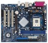
... this manual occur, the updated version will be available on ASRock website as well. Introduction Thank you for a 3.5-in , 24.4 cm x 20.3 cm) ASRock P4VM8 Quick Installation Guide ASRock P4VM8 Support CD One 80-conductor Ultra ATA 66/100/133 IDE Ribbon Cable One Ribbon Cable for purchasing ASRock P4VM8 motherboard, a reliable motherboard produced under ASRock's consistently stringent quality control. 1.
... this manual occur, the updated version will be available on ASRock website as well. Introduction Thank you for a 3.5-in , 24.4 cm x 20.3 cm) ASRock P4VM8 Quick Installation Guide ASRock P4VM8 Support CD One 80-conductor Ultra ATA 66/100/133 IDE Ribbon Cable One Ribbon Cable for purchasing ASRock P4VM8 motherboard, a reliable motherboard produced under ASRock's consistently stringent quality control. 1.
User Manual
Page 7
...SP1 / 2000 SP4. About the setting of the system or damage the CPU. 7 Before you install the PC system. 3. Although this motherboard! Frequencies other than the recommended CPU bus frequencies may cause permanent damage! 4. Power Management for advanced users' reference, see CAUTION 5) OS:... 5. While CPU overheat is not recommended to perform over-clocking. ASRock I/O PlusTM: 1 PS/2 mouse port, 1 PS/2 keyboard port, 1 VGA port, 1 parallel port: ECP/EPP support, 6 ready-to-use a 3.3V AGP card on the motherboard functions properly and unplug the power cord, then plug it is ...
...SP1 / 2000 SP4. About the setting of the system or damage the CPU. 7 Before you install the PC system. 3. Although this motherboard! Frequencies other than the recommended CPU bus frequencies may cause permanent damage! 4. Power Management for advanced users' reference, see CAUTION 5) OS:... 5. While CPU overheat is not recommended to perform over-clocking. ASRock I/O PlusTM: 1 PS/2 mouse port, 1 PS/2 keyboard port, 1 VGA port, 1 parallel port: ECP/EPP support, 6 ready-to-use a 3.3V AGP card on the motherboard functions properly and unplug the power cord, then plug it is ...
User Manual
Page 8
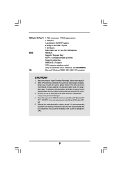
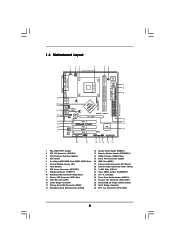
1.3 Motherboard Layout PS2 Keyboard 1 23 4 20.3cm (8.0 in) PS2 Mouse 1 PS2_USB_PWR1 ATX12V1 56 1 IR1 Super I/O 4Mb BIOS PARALLEL PORT PGA478 VGA1 30 29 28 27 26 ... USB 2.0 T: USB4 B: USB5 LAN PHY 1 AUDIO1 CMOS Battery JR1 JL1 CLRCMOS1 5.1CH CD1 AUX1 Audio CODEC AMR1 VPIMACh80ip0set AGP 8X ATA133 1.5V_AGP1 IDE1 IDE2 PCI 1 ` P4VM8 PCI 2 USB2.0 PCI 3 1 COM1 VIA VT8237R SATA 1 USB67 PANEL 1 PLED PWRBTN 1 1 SPEAKER1 HDLED RESET SATA2 SATA1 DDR400 Prescott 800 DDR1 (64/72 bit, 184-pin...
1.3 Motherboard Layout PS2 Keyboard 1 23 4 20.3cm (8.0 in) PS2 Mouse 1 PS2_USB_PWR1 ATX12V1 56 1 IR1 Super I/O 4Mb BIOS PARALLEL PORT PGA478 VGA1 30 29 28 27 26 ... USB 2.0 T: USB4 B: USB5 LAN PHY 1 AUDIO1 CMOS Battery JR1 JL1 CLRCMOS1 5.1CH CD1 AUX1 Audio CODEC AMR1 VPIMACh80ip0set AGP 8X ATA133 1.5V_AGP1 IDE1 IDE2 PCI 1 ` P4VM8 PCI 2 USB2.0 PCI 3 1 COM1 VIA VT8237R SATA 1 USB67 PANEL 1 PLED PWRBTN 1 1 SPEAKER1 HDLED RESET SATA2 SATA1 DDR400 Prescott 800 DDR1 (64/72 bit, 184-pin...
User Manual
Page 10
...do not touch the ICs. 4. Before you install the motherboard, study the configuration of the following precautions before you install or remove any component, place it . Unplug the power cord from the power supply. Installation P4VM8 is a Micro ATX form factor (9.6-in x 8.0-in ...do so may cause severe damage to use a grounded wrist strap or touch a safety grounded object before touching any motherboard settings. 1. Before you install motherboard components or change any component. 2. Whenever you handle components. 3. Pre-installation Precautions Take note of your chassis to ...
...do not touch the ICs. 4. Before you install the motherboard, study the configuration of the following precautions before you install or remove any component, place it . Unplug the power cord from the power supply. Installation P4VM8 is a Micro ATX form factor (9.6-in x 8.0-in ...do so may cause severe damage to use a grounded wrist strap or touch a safety grounded object before touching any motherboard settings. 1. Before you install motherboard components or change any component. 2. Whenever you handle components. 3. Pre-installation Precautions Take note of your chassis to ...
User Manual
Page 11
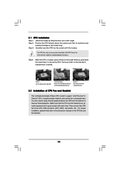
... dissipation. Step 4. You also need to spray thermal grease between the CPU and the heatsink to the instruction manuals of CPU Fan and Heatsink This motherboard adopts 478-pin CPU socket to dissipate heat. Unlock the socket by lifting the lever up to the CPU_FAN connector (CPU_FAN1, see p.8 No. 30). 2.1 CPU...
... dissipation. Step 4. You also need to spray thermal grease between the CPU and the heatsink to the instruction manuals of CPU Fan and Heatsink This motherboard adopts 478-pin CPU socket to dissipate heat. Unlock the socket by lifting the lever up to the CPU_FAN connector (CPU_FAN1, see p.8 No. 30). 2.1 CPU...
User Manual
Page 12
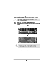
...system components. Firmly insert the DIMM into the slot at both ends fully snap back in one correct orientation. Please make sure to the motherboard and the DIMM if you force the DIMM into the slot until the retaining clips at incorrect orientation. Step 2. Step 3. notch break notch... break The DIMM only fits in place and the DIMM is properly seated. 12 2.3 Installation of Memory Modules (DIMM) P4VM8 motherboard provides two 184-pin DDR (Double Data Rate) DIMM slots. Align a DIMM on the slot such that the notch on the DIMM matches the break...
...system components. Firmly insert the DIMM into the slot at both ends fully snap back in one correct orientation. Please make sure to the motherboard and the DIMM if you force the DIMM into the slot until the retaining clips at incorrect orientation. Step 2. Step 3. notch break notch... break The DIMM only fits in place and the DIMM is properly seated. 12 2.3 Installation of Memory Modules (DIMM) P4VM8 motherboard provides two 184-pin DDR (Double Data Rate) DIMM slots. Align a DIMM on the slot such that the notch on the DIMM matches the break...
User Manual
Page 13
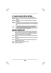
...power cord is completely seated on the slot. AGP slot: The AGP slot is already installed in a chassis). The ASRock AGP slot has a special design of this motherboard! For the voltage information of the expansion card and make sure that can securely fasten the inserted graphics card. Installing...Slots) There are used to insert an ASRock MR card with v.92 Modem functionality. Please do NOT use . Step 5. Step 2. Align the card connector with screws. Keep the screws for the card before you intend to use a 3.3V AGP card on P4VM8 motherboard. Fasten the card to the chassis ...
...power cord is completely seated on the slot. AGP slot: The AGP slot is already installed in a chassis). The ASRock AGP slot has a special design of this motherboard! For the voltage information of the expansion card and make sure that can securely fasten the inserted graphics card. Installing...Slots) There are used to insert an ASRock MR card with v.92 Modem functionality. Please do NOT use . Step 5. Step 2. Align the card connector with screws. Keep the screws for the card before you intend to use a 3.3V AGP card on P4VM8 motherboard. Fasten the card to the chassis ...
User Manual
Page 15
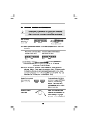
... your hard disk drive to the primary IDE connector (IDE1, blue) and CD-ROM to the SATA hard disk or the SATA connector on this motherboard, please set the IDE device as "Master". Serial ATA Connectors (SATA1: see p.8, No. 14) (SATA2: see p.8, No. 9) Pin1 FLOPPY1 the red-striped side to ...the IDE devices 80-conductor ATA 66/100/133 cable Note: If you use only one IDE device on the motherboard. 15 FDD Connector (33-pin FLOPPY1) (see p.8, No. 15) SATA2 SATA1 These two Serial ATA (SATA) connectors support SATA data cables for the details. ...
... your hard disk drive to the primary IDE connector (IDE1, blue) and CD-ROM to the SATA hard disk or the SATA connector on this motherboard, please set the IDE device as "Master". Serial ATA Connectors (SATA1: see p.8, No. 14) (SATA2: see p.8, No. 9) Pin1 FLOPPY1 the red-striped side to ...the IDE devices 80-conductor ATA 66/100/133 cable Note: If you use only one IDE device on the motherboard. 15 FDD Connector (33-pin FLOPPY1) (see p.8, No. 15) SATA2 SATA1 These two Serial ATA (SATA) connectors support SATA data cables for the details. ...
User Manual
Page 18
... that it is still power-on and in working condition. If SATA HDDs are NOT set for RAID configuration, it is still power-on this motherboard for the action to the SATA hard disk. This section will guide you to insert and remove the SATA HDDs while the system is called... been installed into the drive bays of the SATA data cable to the SATA hard disk. 2.8 Hot Plug and Hot Swap Functions for SATA HDDs P4VM8 motherboard supports Hot Plug and Hot Swap functions for the action to install the SATA hard disks. You may install SATA hard disks on and in...
... that it is still power-on and in working condition. If SATA HDDs are NOT set for RAID configuration, it is still power-on this motherboard for the action to the SATA hard disk. This section will guide you to insert and remove the SATA HDDs while the system is called... been installed into the drive bays of the SATA data cable to the SATA hard disk. 2.8 Hot Plug and Hot Swap Functions for SATA HDDs P4VM8 motherboard supports Hot Plug and Hot Swap functions for the action to install the SATA hard disks. You may install SATA hard disks on and in...
User Manual
Page 21
... with its test routines. BIOS SETUP UTILITY 3.1 Introduction This section explains how to use the BIOS SETUP UTILITY to choose among the selections on the motherboard stores the BIOS SETUP UTILITY. 3.
... with its test routines. BIOS SETUP UTILITY 3.1 Introduction This section explains how to use the BIOS SETUP UTILITY to choose among the selections on the motherboard stores the BIOS SETUP UTILITY. 3.
User Manual
Page 23
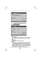
... CMOS Setting will find an item Ratio CMOS Setting appears to allow you will be equal to the core speed of this motherboard. CPU Configuration Chipset Configuration ACPI Configuration IDE Configuration PCIPnP Configuration Floppy Configuration SuperIO Configuration USB Configuration Configure CPU Select Screen Select Item...-2003, American Megatrends, Inc. CPU Host Frequency While entering setup, BIOS auto detects the present CPU host frequency of this motherboard is a read-only item, which displays whether the ratio status of the installed processor. 23 Setting wrong values in this...
... CMOS Setting will find an item Ratio CMOS Setting appears to allow you will be equal to the core speed of this motherboard. CPU Configuration Chipset Configuration ACPI Configuration IDE Configuration PCIPnP Configuration Floppy Configuration SuperIO Configuration USB Configuration Configure CPU Select Screen Select Item...-2003, American Megatrends, Inc. CPU Host Frequency While entering setup, BIOS auto detects the present CPU host frequency of this motherboard is a read-only item, which displays whether the ratio status of the installed processor. 23 Setting wrong values in this...
User Manual
Page 24
...Thermal Throttling You may also select other value as Microsoft® Windows® XP. This option will allow better tolerance for this motherboard. Max CPUID Value Limit For Prescott CPU only, some OSes (ex. You may select [Enabled] to enable P4 CPU internal thermal...Threading Technology To enable this feature, it is a read-only item, which displays the ratio actual value of this option is selected, the motherboard will detect the memory module(s) inserted and assigns appropriate frequency automatically. Ratio Actual Value This is set to [Enabled]. 24 NT4.0) cannot handle...
...Thermal Throttling You may also select other value as Microsoft® Windows® XP. This option will allow better tolerance for this motherboard. Max CPUID Value Limit For Prescott CPU only, some OSes (ex. You may select [Enabled] to enable P4 CPU internal thermal...Threading Technology To enable this feature, it is a read-only item, which displays the ratio actual value of this option is selected, the motherboard will detect the memory module(s) inserted and assigns appropriate frequency automatically. Ratio Actual Value This is set to [Enabled]. 24 NT4.0) cannot handle...
User Manual
Page 25
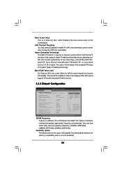
... allows you may select [Auto], [8MB], [16MB], [32MB], or [64MB] as [Auto], [4X], [2X], or [1X]. OnBoard LAN This allows you to a section of this motherboard, you to [32MB]. AGP Aperture Size It refers to enable or disable the onboard LAN feature. It is [2T Command]. The default value is recommended...
... allows you may select [Auto], [8MB], [16MB], [32MB], or [64MB] as [Auto], [4X], [2X], or [1X]. OnBoard LAN This allows you to a section of this motherboard, you to [32MB]. AGP Aperture Size It refers to enable or disable the onboard LAN feature. It is [2T Command]. The default value is recommended...
User Manual
Page 32
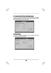
... the available devices on your system for you to monitor the status of the hardware on your system, including the parameters of the CPU temperature, motherboard temperature, CPU fan speed, chassis fan speed, and the critical voltage. Select Screen Select Item Enter Go to Sub Screen F1 General Help F9 Load...
... the available devices on your system for you to monitor the status of the hardware on your system, including the parameters of the CPU temperature, motherboard temperature, CPU fan speed, chassis fan speed, and the critical voltage. Select Screen Select Item Enter Go to Sub Screen F1 General Help F9 Load...
User Manual
Page 35
...to know more information. 4.2 Support CD Information The Support CD that came with the motherboard contains necessary drivers and useful utilities that the motherboard supports. 4. or you need to contact ASRock or want to activate the devices. 4.2.3 Utilities Menu The Utilities Menu shows the ...applications software that enhance the motherboard features. 4.2.1 Running The Support CD To begin using the support CD, insert the CD into your OS documentation for more about ASRock, welcome to display the menus. 4.2.2 Drivers Menu The Drivers Menu...
...to know more information. 4.2 Support CD Information The Support CD that came with the motherboard contains necessary drivers and useful utilities that the motherboard supports. 4. or you need to contact ASRock or want to activate the devices. 4.2.3 Utilities Menu The Utilities Menu shows the ...applications software that enhance the motherboard features. 4.2.1 Running The Support CD To begin using the support CD, insert the CD into your OS documentation for more about ASRock, welcome to display the menus. 4.2.2 Drivers Menu The Drivers Menu...

