
RAID Installation Guide
Page 1
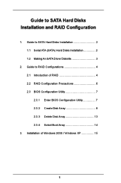
Guide to SATA Hard Disks Installation and RAID Configuration 1. Installation of RAID 4 2.2 RAID Configuration Precautions 6 2.3 BIOS Configuration Utility 7 2.3.1 Enter BIOS Configuration Utility 7 2.3.2 Create Disk Array 8 2.3.3 Delete Disk Array 13 2.3.4 Select Boot Array 14 3. Guide to SATA Hard Disks Installation 2 1.1 Serial ATA (SATA) Hard Disks Installation 2 1.2 Making An SATA Driver Diskette 3 2. Guide to RAID Configurations 4 2.1 Introduction of Windows 2000 / Windows XP 15 1
Guide to SATA Hard Disks Installation and RAID Configuration 1. Installation of RAID 4 2.2 RAID Configuration Precautions 6 2.3 BIOS Configuration Utility 7 2.3.1 Enter BIOS Configuration Utility 7 2.3.2 Create Disk Array 8 2.3.3 Delete Disk Array 13 2.3.4 Select Boot Array 14 3. Guide to SATA Hard Disks Installation 2 1.1 Serial ATA (SATA) Hard Disks Installation 2 1.2 Making An SATA Driver Diskette 3 2. Guide to RAID Configurations 4 2.1 Introduction of Windows 2000 / Windows XP 15 1

RAID Installation Guide
Page 3
... 2: During POST at the following path: .. \ VIA RAID Tool 3 Start to format and copy files [YN]? You may start to use "VT8237 SATA RAID BIOS" to set the RAID configuration by using "VIA RAID Tool" in the folder at the beginning of system boot-up, press key, and then a window... CD, "Guide to VIA RAID Tool", which is located in Windows environment. Formatting the floppy diskette will start the OS installation. STEP 1: Insert the ASRock Support CD into your optical drive to boot your system. (Do NOT insert any floppy diskette into the floppy drive. Once you have the SATA...
... 2: During POST at the following path: .. \ VIA RAID Tool 3 Start to format and copy files [YN]? You may start to use "VT8237 SATA RAID BIOS" to set the RAID configuration by using "VIA RAID Tool" in the folder at the beginning of system boot-up, press key, and then a window... CD, "Guide to VIA RAID Tool", which is located in Windows environment. Formatting the floppy diskette will start the OS installation. STEP 1: Insert the ASRock Support CD into your optical drive to boot your system. (Do NOT insert any floppy diskette into the floppy drive. Once you have the SATA...

RAID Installation Guide
Page 7
2.3 BIOS Configuration Utility 2.3.1 Enter BIOS Configuration Utility After the system powers on, the following information will appear on the screen. Press 'Tab' key to enter BIOS configuration utility. The main interface of BIOS configuration utility is as below: 7
2.3 BIOS Configuration Utility 2.3.1 Enter BIOS Configuration Utility After the system powers on, the following information will appear on the screen. Press 'Tab' key to enter BIOS configuration utility. The main interface of BIOS configuration utility is as below: 7

RAID Installation Guide
Page 9
3. When all drives have been selected, press to go back to select the disk drives and create array automatically. Select "Auto Setup" to allow BIOS to the creation steps menu. 9 One method is "Auto Setup", and another is "Select Disk Drives". When using Select Disk Drives method, the channel column will be activated. Select "Select Disk Drives" to select them respectively. Just highlight the target drives that you want to use and press to let user select the array drives manually. There are two methods to create a disk array.
3. When all drives have been selected, press to go back to select the disk drives and create array automatically. Select "Auto Setup" to allow BIOS to the creation steps menu. 9 One method is "Auto Setup", and another is "Select Disk Drives". When using Select Disk Drives method, the channel column will be activated. Select "Select Disk Drives" to select them respectively. Just highlight the target drives that you want to use and press to let user select the array drives manually. There are two methods to create a disk array.
User Manual
Page 3
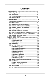
... 21 3.1 Introduction 21 3.1.1 BIOS Menu Bar 21 3.1.2 Navigation Keys 22 3.2 Main Screen 22 3.3 Advanced Screen 23 3.3.1 CPU Configuration 23 3.3.2 Chipset Configuration 24 3.3.3 ACPI Configuration 26 3.3.4 IDE Configuration 27 3.3.5 PCIPnP ... Installation 19 2.8 Hot Plug and Hot Swap Functions for SATA HDDs ....... 19 2.9 Making An SATA Driver Diskette 20 3. Contents 1. Introduction 5 1.1 Package Contents 5 1.2 Specifications 6 1.3 Motherboard Layout 8 1.4 ASRock I/O Plus 9 TM 2.
... 21 3.1 Introduction 21 3.1.1 BIOS Menu Bar 21 3.1.2 Navigation Keys 22 3.2 Main Screen 22 3.3 Advanced Screen 23 3.3.1 CPU Configuration 23 3.3.2 Chipset Configuration 24 3.3.3 ACPI Configuration 26 3.3.4 IDE Configuration 27 3.3.5 PCIPnP ... Installation 19 2.8 Hot Plug and Hot Swap Functions for SATA HDDs ....... 19 2.9 Making An SATA Driver Diskette 20 3. Contents 1. Introduction 5 1.1 Package Contents 5 1.2 Specifications 6 1.3 Motherboard Layout 8 1.4 ASRock I/O Plus 9 TM 2.
User Manual
Page 5
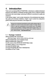
It delivers excellent performance with robust design conforming to ASRock's commitment to BIOS setup and information of the Support CD. ASRock website http://www.asrock.com 1.1 Package Contents ASRock P4V88/P4V88+ Motherboard (ATX Form Factor: 12.0-in x 8.6-in, 30.5 cm x 21.8 cm) ASRock P4V88/P4V88+ Quick Installation Guide ASRock P4V88/P4V88+ Support CD One 80-conductor Ultra ATA 66/100/133 IDE Ribbon Cable...
It delivers excellent performance with robust design conforming to ASRock's commitment to BIOS setup and information of the Support CD. ASRock website http://www.asrock.com 1.1 Package Contents ASRock P4V88/P4V88+ Motherboard (ATX Form Factor: 12.0-in x 8.6-in, 30.5 cm x 21.8 cm) ASRock P4V88/P4V88+ Quick Installation Guide ASRock P4V88/P4V88+ Support CD One 80-conductor Ultra ATA 66/100/133 IDE Ribbon Cable...
User Manual
Page 7
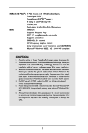
ASRock I/O PlusTM: 1 PS/2 mouse port, 1 PS/2 keyboard port, 1 serial port: COM1, 1 parallel port: ECP/EPP support, 6 ready-to perform over-clocking. Power Management for advanced users' ... AGP slot of the system or damage the CPU. 7 Do NOT use USB 2.0 ports, 1 RJ 45 port, Audio Jack: Line In / Line Out / Microphone BIOS: AMI BIOS Supports "Plug and Play" ACPI 1.1 compliance wake up events Supports jumperfree SMBIOS 2.3.1 support CPU frequency stepless control (only for USB 2.0 works fine under Microsoft®...
ASRock I/O PlusTM: 1 PS/2 mouse port, 1 PS/2 keyboard port, 1 serial port: COM1, 1 parallel port: ECP/EPP support, 6 ready-to perform over-clocking. Power Management for advanced users' ... AGP slot of the system or damage the CPU. 7 Do NOT use USB 2.0 ports, 1 RJ 45 port, Audio Jack: Line In / Line Out / Microphone BIOS: AMI BIOS Supports "Plug and Play" ACPI 1.1 compliance wake up events Supports jumperfree SMBIOS 2.3.1 support CPU frequency stepless control (only for USB 2.0 works fine under Microsoft®...
User Manual
Page 8
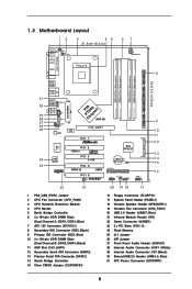
... USB4_5 ATXPWR1 CD1 AUX1 1 JR1 AUDIO1 JL1 Audio CODEC LAN PHY VPIACT8h8ip0seAtGP 8X 1.5V_AGP1 PCI 1 IDE1 SATA2 Super I/O 2MB BIOS GAME1 PCI 2 USB2.0 FSB800 DDR400 PCI 3 5.1 CH PCI 4 ATA133 SATA PCI 5 1 IR1 P4V88+ VIA VT8237 CMOS Battery CLRCMOS1 FLOPPY1 SATA1 USB67 1 CHA_FAN1 SPEAKER1 1 PANEL 1 PLED PWRBTN 1 HDLED RESET 9 10 11 12 13...
... USB4_5 ATXPWR1 CD1 AUX1 1 JR1 AUDIO1 JL1 Audio CODEC LAN PHY VPIACT8h8ip0seAtGP 8X 1.5V_AGP1 PCI 1 IDE1 SATA2 Super I/O 2MB BIOS GAME1 PCI 2 USB2.0 FSB800 DDR400 PCI 3 5.1 CH PCI 4 ATA133 SATA PCI 5 1 IR1 P4V88+ VIA VT8237 CMOS Battery CLRCMOS1 FLOPPY1 SATA1 USB67 1 CHA_FAN1 SPEAKER1 1 PANEL 1 PLED PWRBTN 1 HDLED RESET 9 10 11 12 13...
User Manual
Page 15
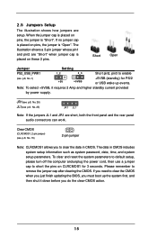
Clear CMOS (CLRCMOS1, 2-pin jumper) (see p.8, No. 15) 2-pin jumper Note: CLRCMOS1 allows you to clear the CMOS when you just finish updating the BIOS, you must boot up events. 2.5 Jumpers Setup The illustration shows how jumpers are "Short" when jumper cap is placed on these 2 pins. Note: To select +...
Clear CMOS (CLRCMOS1, 2-pin jumper) (see p.8, No. 15) 2-pin jumper Note: CLRCMOS1 allows you to clear the CMOS when you just finish updating the BIOS, you must boot up events. 2.5 Jumpers Setup The illustration shows how jumpers are "Short" when jumper cap is placed on these 2 pins. Note: To select +...
User Manual
Page 20
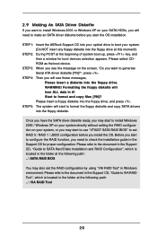
...configuration before you start to configure the RAID function, you need to make an SATA driver diskette before you install the OS. STEP 1: Insert the ASRock Support CD into your optical drive to boot your system. (Do NOT insert any floppy diskette into the floppy drive at this moment!) STEP 2: During... format and copy files [YN]? STEP 5: The system will need to check the installation guide in the folder at the following path: .. \ SATA RAID BIOS You may start to format the floppy diskette and copy SATA drivers into the floppy diskette. Please refer to the document in the Support CD...
...configuration before you start to configure the RAID function, you need to make an SATA driver diskette before you install the OS. STEP 1: Insert the ASRock Support CD into your optical drive to boot your system. (Do NOT insert any floppy diskette into the floppy drive at this moment!) STEP 2: During... format and copy files [YN]? STEP 5: The system will need to check the installation guide in the folder at the following path: .. \ SATA RAID BIOS You may start to format the floppy diskette and copy SATA drivers into the floppy diskette. Please refer to the document in the Support CD...
User Manual
Page 21
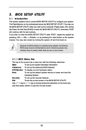
...and then back on the menu bar, and then press to choose among the selections on . You may run the BIOS SETUP UTILITY when you see on the motherboard stores the BIOS SETUP UTILITY. The Flash Memory on your system. Please press during the Power-On-Self-Test (POST) to enter ...the BIOS SETUP UTILITY, otherwise, POST will continue with the following BIOS setup screens and descriptions are for reference purpose only, and they may not exactly match what you start up the security...
...and then back on the menu bar, and then press to choose among the selections on . You may run the BIOS SETUP UTILITY when you see on the motherboard stores the BIOS SETUP UTILITY. The Flash Memory on your system. Please press during the Power-On-Self-Test (POST) to enter ...the BIOS SETUP UTILITY, otherwise, POST will continue with the following BIOS setup screens and descriptions are for reference purpose only, and they may not exactly match what you start up the security...
User Manual
Page 22
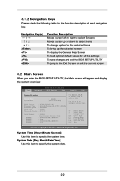
...(C) Copyright 1985-2003, American Megatrends, Inc. 3.1.2 Navigation Keys Please check the following table for all the settings To save changes and exit the BIOS SETUP UTILITY To jump to the Exit Screen or exit the current screen 3.2 Main Screen When you enter the... UTILITY Main Advanced H/W Monitor Boot Security Exit System Overview System Time System Date [17:00:09] [Wed 12/22/2004] BIOS Version : P4V88+ BIOS P1.00 Processor Type : Intel (R) Pentium (R) 4 CPU 2.40 GHz Processor Speed : 2400 MHz Cache Size : 512KB Microcode Update : 0F24/1E Total Memory DIMM 1 DIMM 2 ...
...(C) Copyright 1985-2003, American Megatrends, Inc. 3.1.2 Navigation Keys Please check the following table for all the settings To save changes and exit the BIOS SETUP UTILITY To jump to the Exit Screen or exit the current screen 3.2 Main Screen When you enter the... UTILITY Main Advanced H/W Monitor Boot Security Exit System Overview System Time System Date [17:00:09] [Wed 12/22/2004] BIOS Version : P4V88+ BIOS P1.00 Processor Type : Intel (R) Pentium (R) 4 CPU 2.40 GHz Processor Speed : 2400 MHz Cache Size : 512KB Microcode Update : 0F24/1E Total Memory DIMM 1 DIMM 2 ...
User Manual
Page 23
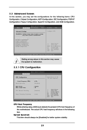
...SuperIO Configuration USB Configuration Configure CPU Select Screen Select Item Enter Go to malfunction. CPU Host Frequency While entering setup, BIOS auto detects the present CPU host frequency of this section may cause system to Sub Screen F1 General Help F9 ...2003, American Megatrends, Inc. The actual CPU host frequency will show in below sections may cause the system to malfunction. 3.3.1 CPU Configuration BIOS SETUP UTILITY Advanced CPU Configuration CPU Host Frequency Actual Frequency (MHz) Spread Spectrum Ratio Status Ratio Actual Value CPU Thermal Throttling [Auto] [...
...SuperIO Configuration USB Configuration Configure CPU Select Screen Select Item Enter Go to malfunction. CPU Host Frequency While entering setup, BIOS auto detects the present CPU host frequency of this section may cause system to Sub Screen F1 General Help F9 ...2003, American Megatrends, Inc. The actual CPU host frequency will show in below sections may cause the system to malfunction. 3.3.1 CPU Configuration BIOS SETUP UTILITY Advanced CPU Configuration CPU Host Frequency Actual Frequency (MHz) Spread Spectrum Ratio Status Ratio Actual Value CPU Thermal Throttling [Auto] [...
User Manual
Page 24
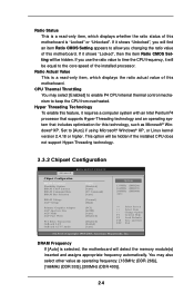
... to the core speed of the installed processor. If it will be hidden if the installed CPU does not support Hyper-Threading technology. 3.3.2 Chipset Configuration BIOS SETUP UTILITY Advanced Chipset Configuration DRAM Frequency Flexibility Option DRAM CAS# Latency DRAM Command Rate DRAM Bus Selection [Auto] [Disabled] [Auto] [2T Command] [Auto] DRAM...
... to the core speed of the installed processor. If it will be hidden if the installed CPU does not support Hyper-Threading technology. 3.3.2 Chipset Configuration BIOS SETUP UTILITY Advanced Chipset Configuration DRAM Frequency Flexibility Option DRAM CAS# Latency DRAM Command Rate DRAM Bus Selection [Auto] [Disabled] [Auto] [2T Command] [Auto] DRAM...
User Manual
Page 26
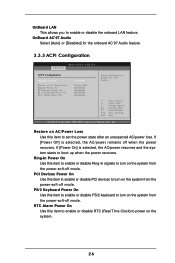
... power state after an unexpected AC/power loss. OnBoard AC'97 Audio Select [Auto] or [Disabled] for the onboard AC'97 Audio feature. 3.3.3 ACPI Configuration BIOS SETUP UTILITY Advanced ACPI Configuration Suspend To RAM Restore on the system. 26 Restore on AC/Power Loss Use this item to enable or disable...
... power state after an unexpected AC/power loss. OnBoard AC'97 Audio Select [Auto] or [Disabled] for the onboard AC'97 Audio feature. 3.3.3 ACPI Configuration BIOS SETUP UTILITY Advanced ACPI Configuration Suspend To RAM Restore on the system. 26 Restore on AC/Power Loss Use this item to enable or disable...
User Manual
Page 27
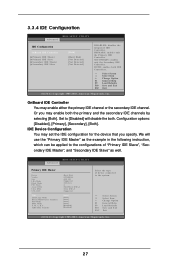
... the secondary IDE channels by selecting [Both]. Set to [Disabled] will use the "Primary IDE Master" as well. Advanced BIOS SETUP UTILITY Primary IDE Master Device Vendor Size LBA Mode Block Mode PIO Mode Async DMA Ultra DMA S.M.A.R.T. PRIMARY: enables only...Copyright 1985-2003, American Megatrends, Inc. 27 SECONDARY: enables only the Secondary IDE Controller. BOTH: enables both . 3.3.4 IDE Configuration Advanced BIOS SETUP UTILITY IDE Configuration OnBoard IDE Controller Primary IDE Master Primary IDE Slave Secondary IDE Master Secondary IDE Slave [Both] [Hard Disk] [...
... the secondary IDE channels by selecting [Both]. Set to [Disabled] will use the "Primary IDE Master" as well. Advanced BIOS SETUP UTILITY Primary IDE Master Device Vendor Size LBA Mode Block Mode PIO Mode Async DMA Ultra DMA S.M.A.R.T. PRIMARY: enables only...Copyright 1985-2003, American Megatrends, Inc. 27 SECONDARY: enables only the Secondary IDE Controller. BOTH: enables both . 3.3.4 IDE Configuration Advanced BIOS SETUP UTILITY IDE Configuration OnBoard IDE Controller Primary IDE Master Primary IDE Slave Secondary IDE Master Secondary IDE Slave [Both] [Hard Disk] [...
User Manual
Page 28
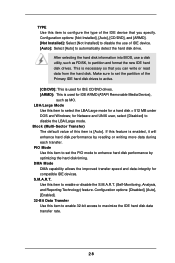
... device. [Auto]: Select [Auto] to enhance hard disk performance by reading or writing more data during each transfer. After selecting the hard disk information into BIOS, use of this item to select the LBA/Large mode for a hard disk > 512 MB under DOS and Windows; Configuration options: [Disabled], [Auto], [Enabled]. 32...
... device. [Auto]: Select [Auto] to enhance hard disk performance by reading or writing more data during each transfer. After selecting the hard disk information into BIOS, use of this item to select the LBA/Large mode for a hard disk > 512 MB under DOS and Windows; Configuration options: [Disabled], [Auto], [Enabled]. 32...
User Manual
Page 29
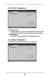
...Floppy Configuration In this item to keep the default value unless the installed PCI expansion cards' specifications require other settings. 3.3.5 PCIPnP Configuration BIOS SETUP UTILITY Advanced PCI / PnP Configuration PCI Latency Timer PCI IDE BusMaster [32] [Enabled] Value in units of floppy drive connected ... Item Change Option General Help Load Defaults Save and Exit Exit v02.54 (C) Copyright 1985-2003, American Megatrends, Inc. 29 Advanced BIOS SETUP UTILITY Floppy Configuration Floppy A Floppy B [1.44 MB 312"] [Disabled] Select the type of PCI clocks for PCI device latency...
...Floppy Configuration In this item to keep the default value unless the installed PCI expansion cards' specifications require other settings. 3.3.5 PCIPnP Configuration BIOS SETUP UTILITY Advanced PCI / PnP Configuration PCI Latency Timer PCI IDE BusMaster [32] [Enabled] Value in units of floppy drive connected ... Item Change Option General Help Load Defaults Save and Exit Exit v02.54 (C) Copyright 1985-2003, American Megatrends, Inc. 29 Advanced BIOS SETUP UTILITY Floppy Configuration Floppy A Floppy B [1.44 MB 312"] [Disabled] Select the type of PCI clocks for PCI device latency...
User Manual
Page 30
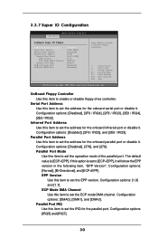
...], [3E8 / IRQ4], [2E8 / IRQ3]. If this option is [ECP+EPP]. Configuration options: [DMA0], [DMA1], and [DMA3]. 3.3.7 Super IO Configuration Advanced BIOS SETUP UTILITY Configure Super IO Chipset OnBoard Floppy Controller Serial Port Address Infrared Port Address Parallel Port Address Parallel Port Mode EPP Version ECP Mode...OnBoard MIDI Port [Enabled] [3F8 / IRQ4] [Disabled] [378] [ECP + EPP] [1.9] [DMA3] [IRQ7] [Enabled] [Disabled] Allow BIOS to set the IRQ for the onboard serial port or disable it will show the EPP version in the following item, "EPP Version". OnBoard Floppy...
...], [3E8 / IRQ4], [2E8 / IRQ3]. If this option is [ECP+EPP]. Configuration options: [DMA0], [DMA1], and [DMA3]. 3.3.7 Super IO Configuration Advanced BIOS SETUP UTILITY Configure Super IO Chipset OnBoard Floppy Controller Serial Port Address Infrared Port Address Parallel Port Address Parallel Port Mode EPP Version ECP Mode...OnBoard MIDI Port [Enabled] [3F8 / IRQ4] [Disabled] [378] [ECP + EPP] [1.9] [DMA3] [IRQ7] [Enabled] [Disabled] Allow BIOS to set the IRQ for the onboard serial port or disable it will show the EPP version in the following item, "EPP Version". OnBoard Floppy...
User Manual
Page 31
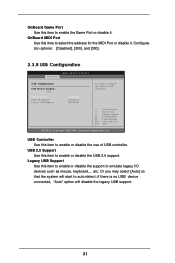
...; Or you may select [Auto] so that the system will disable the legacy USB support. 31 Configuration options: [Disabled], [300], and [330]. 3.3.8 USB Configuration Advanced BIOS SETUP UTILITY USB Configuration USB Devices Enabled : None USB Controller USB 2.0 Support Legacy USB Support [Enabled] [Enabled] [Disabled] To enable or disable the onboard USB...
...; Or you may select [Auto] so that the system will disable the legacy USB support. 31 Configuration options: [Disabled], [300], and [330]. 3.3.8 USB Configuration Advanced BIOS SETUP UTILITY USB Configuration USB Devices Enabled : None USB Controller USB 2.0 Support Legacy USB Support [Enabled] [Enabled] [Disabled] To enable or disable the onboard USB...


