User Manual
Page 3
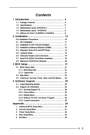
... Contents 4 1.2 Specifications 5 1.3 Motherboard Layout (P4S55FX 7 1.4 Motherboard Layout (P4S55FX 8 1.5 ASRock I/O PlusTM (P4S55FX+/ P4S55FX 9 2 Installation 10 Pre-installation Precautions 10 2.1 CPU Installation 11 2.2 Installation of CPU Fan and Heatsink 11 2.3 Installation of Memory Modules (DIMM 12 2.4 Expansion Slots (PCI and AGP Slots 14 2.5 Jumpers Setup 15 2.6 Onboard Headers and Connectors 16 2.7 Serial ATA (SATA) Hard Disks Installation 19...
... Contents 4 1.2 Specifications 5 1.3 Motherboard Layout (P4S55FX 7 1.4 Motherboard Layout (P4S55FX 8 1.5 ASRock I/O PlusTM (P4S55FX+/ P4S55FX 9 2 Installation 10 Pre-installation Precautions 10 2.1 CPU Installation 11 2.2 Installation of CPU Fan and Heatsink 11 2.3 Installation of Memory Modules (DIMM 12 2.4 Expansion Slots (PCI and AGP Slots 14 2.5 Jumpers Setup 15 2.6 Onboard Headers and Connectors 16 2.7 Serial ATA (SATA) Hard Disks Installation 19...
User Manual
Page 4
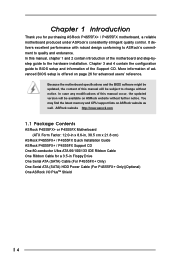
... support lists on page 26 for advanced users' reference. ASRock website http://www.asrock.com 1.1 Package Contents ASRock P4S55FX+ or P4S55FX Motherboard (ATX Form Factor: 12.0-in x 8.6-in Floppy Drive One Serial ATA (SATA) Cable (For P4S55FX+ Only) One Serial ATA (SATA) HDD Power Cable (For P4S55FX+ Only)(Optional) One ASRock I/O PlusTM Shield 4 Because the motherboard specifications and the BIOS...
... support lists on page 26 for advanced users' reference. ASRock website http://www.asrock.com 1.1 Package Contents ASRock P4S55FX+ or P4S55FX Motherboard (ATX Form Factor: 12.0-in x 8.6-in Floppy Drive One Serial ATA (SATA) Cable (For P4S55FX+ Only) One Serial ATA (SATA) HDD Power Cable (For P4S55FX+ Only)(Optional) One ASRock I/O PlusTM Shield 4 Because the motherboard specifications and the BIOS...

User Manual
Page 5
... Bridge: SiS 655FX, FSB @ 800/533/400 MHz, with Intel® Hyper-Threading Technology ready South Bridge: P4S55FX+: SiS 964, supports USB 2.0, ATA 133, SATA 1.5Gb/s P4S55FX: SiS 964L, supports USB 2.0, ATA 133 Memory: 4 DDR DIMM Slots: DDR1, DDR2, DDR3, and DDR4 Supports...SATA is only available on P4S55FX+ Motherboard) Floppy Port: Supports up to 2 floppy disk drives Audio: 5.1 channels AC'97 Audio LAN: Speed: 802.3u (10/100 Ethernet), supports Wake-On-LAN Hardware Monitor: CPU temperature sensing Chassis temperature sensing CPU overheat shutdown to protect CPU life (ASRock...
... Bridge: SiS 655FX, FSB @ 800/533/400 MHz, with Intel® Hyper-Threading Technology ready South Bridge: P4S55FX+: SiS 964, supports USB 2.0, ATA 133, SATA 1.5Gb/s P4S55FX: SiS 964L, supports USB 2.0, ATA 133 Memory: 4 DDR DIMM Slots: DDR1, DDR2, DDR3, and DDR4 Supports...SATA is only available on P4S55FX+ Motherboard) Floppy Port: Supports up to 2 floppy disk drives Audio: 5.1 channels AC'97 Audio LAN: Speed: 802.3u (10/100 Ethernet), supports Wake-On-LAN Hardware Monitor: CPU temperature sensing Chassis temperature sensing CPU overheat shutdown to protect CPU life (ASRock...
User Manual
Page 7
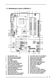
1.3 Motherboard Layout (P4S55FX+) 1 23 45 6 7 21.8cm (8.6 in) PS2 Mouse PS2 Keyboard 1 PS2_USB_PWR1 CPU_FAN1 ATX12V1 PARALLEL PORT COM1 PGA478 IDE2 8 DDR1 (64/72 bit, 184-pin module) DDR2 (... 2.0 T: USB4 B: USB5 CD1 AUDIO1 1 AUX1 JR1 JL1 Audio CODEC Super I/O 24 23 2MB BIOS ATXPWR1 SiS 655FX LAN 1.5V_AGP1 PHY PCI 1 9 IDE1 10 11 PCI 2 P4S55FX+ SATA PCI 3 PCI 4 AGP 8X DDR400 PCI 5 GAME1 FSB800 USB2.0 5.1 CH ATA133 FLOPPY1 USB67 1 SiS 964 SATA2 SATA1 CMOS Battery SPEAKER1 1 CLRCMOS1 CHA_FAN1 IR1 1 PANEL 1 PLED...
1.3 Motherboard Layout (P4S55FX+) 1 23 45 6 7 21.8cm (8.6 in) PS2 Mouse PS2 Keyboard 1 PS2_USB_PWR1 CPU_FAN1 ATX12V1 PARALLEL PORT COM1 PGA478 IDE2 8 DDR1 (64/72 bit, 184-pin module) DDR2 (... 2.0 T: USB4 B: USB5 CD1 AUDIO1 1 AUX1 JR1 JL1 Audio CODEC Super I/O 24 23 2MB BIOS ATXPWR1 SiS 655FX LAN 1.5V_AGP1 PHY PCI 1 9 IDE1 10 11 PCI 2 P4S55FX+ SATA PCI 3 PCI 4 AGP 8X DDR400 PCI 5 GAME1 FSB800 USB2.0 5.1 CH ATA133 FLOPPY1 USB67 1 SiS 964 SATA2 SATA1 CMOS Battery SPEAKER1 1 CLRCMOS1 CHA_FAN1 IR1 1 PANEL 1 PLED...

User Manual
Page 16
...) (see p.7 No. 14) SATA2 SATA1 Serial ATA (SATA) connectors are NOT jumpers. Serial ATA (SATA) Data Cable (Only for the details. 2.6 Onboard Headers and Connectors Onboard headers and connectors are only available on P4S55FX+ motherboard. Placing jumper caps over these headers and connectors.... The current SATA interface allows up to the SATA hard disk or the SATA connector on the motherboard. Serial ATA Connectors (Only on this ...
...) (see p.7 No. 14) SATA2 SATA1 Serial ATA (SATA) connectors are NOT jumpers. Serial ATA (SATA) Data Cable (Only for the details. 2.6 Onboard Headers and Connectors Onboard headers and connectors are only available on P4S55FX+ motherboard. Placing jumper caps over these headers and connectors.... The current SATA interface allows up to the SATA hard disk or the SATA connector on the motherboard. Serial ATA Connectors (Only on this ...
User Manual
Page 17
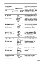
...on each drive. Please connect the chassis speaker to this USB 2.0 header is an interface for P4S55FX+ motherboard) (Optional) connect to the SATA HDD power connector connect to the power supply Please connect the black end of SATA power cable to support 2 additional USB 2.0 ports. If the rear USB ports are not ...pin IR1) (see p.7 No.26 / p.8 No. 24) GND +5VA BACKOUT-R BACKOUT-L 1 A U D - USB 2.0 Header (9-pin USB67) (see p.7 No. 21 / p.8 No. 19) USB_PWR P-7 P+7 GND DUMMY 1 GND P+6 P-6 USB_PWR ASRock I/O PlusTM provides you to the power connector of the power supply. L GND A U D -
...on each drive. Please connect the chassis speaker to this USB 2.0 header is an interface for P4S55FX+ motherboard) (Optional) connect to the SATA HDD power connector connect to the power supply Please connect the black end of SATA power cable to support 2 additional USB 2.0 ports. If the rear USB ports are not ...pin IR1) (see p.7 No.26 / p.8 No. 24) GND +5VA BACKOUT-R BACKOUT-L 1 A U D - USB 2.0 Header (9-pin USB67) (see p.7 No. 21 / p.8 No. 19) USB_PWR P-7 P+7 GND DUMMY 1 GND P+6 P-6 USB_PWR ASRock I/O PlusTM provides you to the power connector of the power supply. L GND A U D -

User Manual
Page 19
...cannot perform Hot Plug if the OS has been installed into the drive bays of the SATA data cable to the motherboard's primary SATA connector (SATA1). You may install SATA hard disks on our website www.asrock.com NOTE What is Hot Swap Function? STEP 3: Connect the other end of your ... for RAID configuration, it is called "Hot Plug" for SATA Devices. Usually, each power wire will guide you to connect SATA HDDs to different power wires to the SATA hard disk. 2.8 Hot Plug and Hot Swap Functions for SATA HDDs P4S55FX+ motherboard supports Hot Plug function for the action to insert ...
...cannot perform Hot Plug if the OS has been installed into the drive bays of the SATA data cable to the motherboard's primary SATA connector (SATA1). You may install SATA hard disks on our website www.asrock.com NOTE What is Hot Swap Function? STEP 3: Connect the other end of your ... for RAID configuration, it is called "Hot Plug" for SATA Devices. Usually, each power wire will guide you to connect SATA HDDs to different power wires to the SATA hard disk. 2.8 Hot Plug and Hot Swap Functions for SATA HDDs P4S55FX+ motherboard supports Hot Plug function for the action to insert ...

User Manual
Page 20
...up, press key, and then a window for boot devices selection appears. STEP 4: Then you need to boot your optical drive to make an SATA driver diskette before you install the OS. Please insert a floppy diskette into the floppy drive at this moment!) STEP 2: During POST at the following... path: .. \ RAID Utility for Windows 20 2.9 Making An SATA Driver Diskette If you want to set the RAID configuration by using "SiS RAID Utility for Windows" in it! STEP 1: Insert the ASRock Support CD into your system. (Do NOT insert any floppy diskette into the floppy...
...up, press key, and then a window for boot devices selection appears. STEP 4: Then you need to boot your optical drive to make an SATA driver diskette before you install the OS. Please insert a floppy diskette into the floppy drive at this moment!) STEP 2: During POST at the following... path: .. \ RAID Utility for Windows 20 2.9 Making An SATA Driver Diskette If you want to set the RAID configuration by using "SiS RAID Utility for Windows" in it! STEP 1: Insert the ASRock Support CD into your system. (Do NOT insert any floppy diskette into the floppy...

User Manual
Page 29
... Port Parallel Port Mode EPP Version Parallel Port IRQ Parallel Port DMA Channel OnBoard Midi Port Midi IRQ Select OnBoard Game Port OnBoard IDE OnBoard SATA OnBoard LAN OnBoard AC' 97 Audio Auto Auto Disabled Auto ECP + EPP 1.9 Auto Auto Disabled 5 200H Both Enabled Enabled Auto to select PCI clocks. Peripheral...
... Port Parallel Port Mode EPP Version Parallel Port IRQ Parallel Port DMA Channel OnBoard Midi Port Midi IRQ Select OnBoard Game Port OnBoard IDE OnBoard SATA OnBoard LAN OnBoard AC' 97 Audio Auto Auto Disabled Auto ECP + EPP 1.9 Auto Auto Disabled 5 200H Both Enabled Enabled Auto to select PCI clocks. Peripheral...

User Manual
Page 30
...], [2E8 / IRQ3 / COM4]. Configuration options: [Disabled], [330], [300]. OnBoard IDE: This allows you to enable or disable the onboard SATA controller. Parallel Port Mode: Set the operation mode of the hardware on -board serial ports or disable serial ports. Configuration options: [Disabled], [200...], [208]. OnBoard SATA: This allows you to enable or disable the onboard IDE controller. Advanced AMIBIOS SETUP UTILITY - OnBoard Game Port: Select address for P4S55FX+ motherboard. Or you to enable or disable the onboard...
...], [2E8 / IRQ3 / COM4]. Configuration options: [Disabled], [330], [300]. OnBoard IDE: This allows you to enable or disable the onboard SATA controller. Parallel Port Mode: Set the operation mode of the hardware on -board serial ports or disable serial ports. Configuration options: [Disabled], [200...], [208]. OnBoard SATA: This allows you to enable or disable the onboard IDE controller. Advanced AMIBIOS SETUP UTILITY - OnBoard Game Port: Select address for P4S55FX+ motherboard. Or you to enable or disable the onboard...
