RAID Installation Guide
Page 2
... Intel Matrix Storage. Please read the RAID configurations in the support CD. Guide to Serial ATA (SATA) Hard Disks Installation of "User Manual" in this motherboard for internal storage devices. You may install SATA hard disks on SATA ports. 2 This section will guide you how to create RAID on this guide...
... Intel Matrix Storage. Please read the RAID configurations in the support CD. Guide to Serial ATA (SATA) Hard Disks Installation of "User Manual" in this motherboard for internal storage devices. You may install SATA hard disks on SATA ports. 2 This section will guide you how to create RAID on this guide...
RAID Installation Guide
Page 3
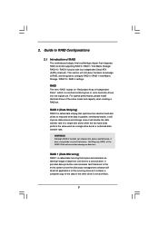
... called data mirroring that copies and maintains an identical image of the data in parallel, interleaved stacks. Guide to RAID Configurations 2.1 Introduction of RAID This motherboard adopts Intel southbridge chipset that optimizes two identical hard disk drives to the surviving drive as a single drive but at a sustained data transfer rate. 2.
... called data mirroring that copies and maintains an identical image of the data in parallel, interleaved stacks. Guide to RAID Configurations 2.1 Introduction of RAID This motherboard adopts Intel southbridge chipset that optimizes two identical hard disk drives to the surviving drive as a single drive but at a sustained data transfer rate. 2.
RAID Installation Guide
Page 8
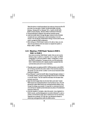
... Ready" system as the source hard drive. 1. you will be used . It's important to understand what will need another SATA / SATAII hard drive with your motherboard or after downloading it as prompted. This will activate the Create RAID volume from Existing Hard Drive Wizard. Open the Intel Storage Utility from the...
... Ready" system as the source hard drive. 1. you will be used . It's important to understand what will need another SATA / SATAII hard drive with your motherboard or after downloading it as prompted. This will activate the Create RAID volume from Existing Hard Drive Wizard. Open the Intel Storage Utility from the...
User Manual
Page 2
...should not be constructed as a commitment by the purchaser for backup purpose, without intent to the implied warranties or conditions of ASRock Inc. "Perchlorate Material-special handling may appear in this manual. Operation is subject to the following two conditions: (1) this ... to infringe. CALIFORNIA, USA ONLY The Lithium battery adopted on this motherboard contains Perchlorate, a toxic substance controlled in this manual may or may not cause harmful interference, and (2) this manual, ASRock does not provide warranty of any interference received, including interference that may...
...should not be constructed as a commitment by the purchaser for backup purpose, without intent to the implied warranties or conditions of ASRock Inc. "Perchlorate Material-special handling may appear in this manual. Operation is subject to the following two conditions: (1) this ... to infringe. CALIFORNIA, USA ONLY The Lithium battery adopted on this motherboard contains Perchlorate, a toxic substance controlled in this manual may or may not cause harmful interference, and (2) this manual, ASRock does not provide warranty of any interference received, including interference that may...
User Manual
Page 3
...1 Introduction 5 1.1 Package Contents 5 1.2 Specifications 6 1.3 Motherboard Layout (P45XE-WiFiN / P45XE-R 11 1.4 Motherboard Layout (P45XE 12 1.5 ASRock DualLAN_SPDIF I/O (P45XE-WiFiN 13 1.6 ASRock DualLAN_SPDIF I/O (P45XE-R 14 1.7 ASRock SPDIF I/O Plus (P45XE 15 1.8 ASRock WiFi-802.11n Module Specifications (For P45XE-WiFiN Only 16 2 Installation 17 2.1 Screw Holes 17 ...2.18 Installing Windows® XP / XP 64-bit / VistaTM / VistaTM 64-bit With RAID Functions (For P45XE-WiFiN / P45XE-R Only 44 2.18.1 Installing Windows® XP / XP 64-bit With RAID Functions 44 2.18.2 Setting ...
...1 Introduction 5 1.1 Package Contents 5 1.2 Specifications 6 1.3 Motherboard Layout (P45XE-WiFiN / P45XE-R 11 1.4 Motherboard Layout (P45XE 12 1.5 ASRock DualLAN_SPDIF I/O (P45XE-WiFiN 13 1.6 ASRock DualLAN_SPDIF I/O (P45XE-R 14 1.7 ASRock SPDIF I/O Plus (P45XE 15 1.8 ASRock WiFi-802.11n Module Specifications (For P45XE-WiFiN Only 16 2 Installation 17 2.1 Screw Holes 17 ...2.18 Installing Windows® XP / XP 64-bit / VistaTM / VistaTM 64-bit With RAID Functions (For P45XE-WiFiN / P45XE-R Only 44 2.18.1 Installing Windows® XP / XP 64-bit With RAID Functions 44 2.18.2 Setting ...
User Manual
Page 5
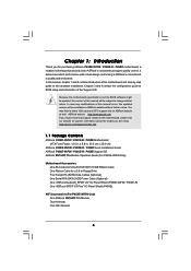
... Contents ASRock P45XE-WiFiN / P45XE-R / P45XE Motherboard (ATX Form Factor: 12.0-in x 8.8-in, 30.5 cm x 22.4 cm) ASRock P45XE-WiFiN / P45XE-R / P45XE Quick Installation Guide ASRock P45XE-WiFiN / P45XE-R / P45XE Support CD ASRock WiFi-802.11n Module Operation Guide (For P45XE-WiFiN Only) Motherboard Accessories One 80-conductor Ultra ATA 66/100/133 IDE Ribbon Cable One Ribbon Cable for purchasing ASRock P45XE-WiFiN / P45XE-R / P45XE motherboard, a reliable motherboard produced under ASRock's consistently...
... Contents ASRock P45XE-WiFiN / P45XE-R / P45XE Motherboard (ATX Form Factor: 12.0-in x 8.8-in, 30.5 cm x 22.4 cm) ASRock P45XE-WiFiN / P45XE-R / P45XE Quick Installation Guide ASRock P45XE-WiFiN / P45XE-R / P45XE Support CD ASRock WiFi-802.11n Module Operation Guide (For P45XE-WiFiN Only) Motherboard Accessories One 80-conductor Ultra ATA 66/100/133 IDE Ribbon Cable One Ribbon Cable for purchasing ASRock P45XE-WiFiN / P45XE-R / P45XE motherboard, a reliable motherboard produced under ASRock's consistently...
User Manual
Page 9
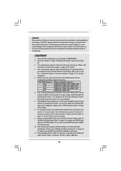
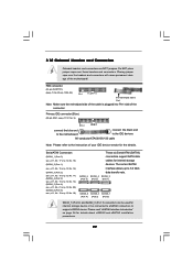
... be overclocked to SATAII connector, please read "Untied Overclocking Technology" on page 50 for details. 4. This motherboard supports Untied Overclocking Technology. channel, 6-channel, and 8-channel modes. CAUTION! 1. Please check the table below for proper connection...Interface Introduction" on page 21 for details about eSATAII and eSATAII installation procedures. 11. For microphone input, this motherboard supports 2-channel, 4- This motherboard supports eSATAII interface, the external SATAII specification. We are not responsible for USB 2.0 works fine under Windows&#...
... be overclocked to SATAII connector, please read "Untied Overclocking Technology" on page 50 for details. 4. This motherboard supports Untied Overclocking Technology. channel, 6-channel, and 8-channel modes. CAUTION! 1. Please check the table below for proper connection...Interface Introduction" on page 21 for details about eSATAII and eSATAII installation procedures. 11. For microphone input, this motherboard supports 2-channel, 4- This motherboard supports eSATAII interface, the external SATAII specification. We are not responsible for USB 2.0 works fine under Windows&#...
User Manual
Page 10
... to support 2 USB 2.0 ports. To improve heat dissipation, remember to create a wireless environment and enjoy the convenience of ASRock OC Tuner. Although this motherboard offers stepless control, it is a revolutionary technology that delivers unparalleled power savings. It is able to -use IDE mode under...performance under Windows® 2000 OS. While CPU overheat is a user-friendly ASRock overclocking tool which allows you resume the system, please check if the CPU fan on the motherboard functions properly and unplug the power cord, then plug it is recommended to ...
... to support 2 USB 2.0 ports. To improve heat dissipation, remember to create a wireless environment and enjoy the convenience of ASRock OC Tuner. Although this motherboard offers stepless control, it is a revolutionary technology that delivers unparalleled power savings. It is able to -use IDE mode under...performance under Windows® 2000 OS. While CPU overheat is a user-friendly ASRock overclocking tool which allows you resume the system, please check if the CPU fan on the motherboard functions properly and unplug the power cord, then plug it is recommended to ...
User Manual
Page 12
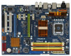
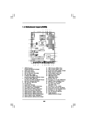
1.4 Motherboard Layout (P45XE) 1 2 3 45 6 7 22.4cm (8.8 in) eSATAII_TOP (Port 4) eSATAII_BOTTOM (Port 5) PS2 Mouse PS2 Keyboard SPDIF Coaxial SPDIF Optical CPU_FAN1 1 PS2_USB_PWR1 DDRII_B1 (64 bit, 240-pin module) DDRII_B2 (..., 240-pin module) USB 2.0 T: USB2 B: USB3 Top: SIDE SPK Center: REAR SPK Bottom: CTR BASS USB 2.0 T: USB4 B: USB5 Intel P45 IDE1 ATX12V1 Chipset LAN PHY P45XE Top: LINE IN Center: FRONT Bottom: MIC IN PCIE1 RoHS PCI Express 2.0 AUDIO CODEC CD1 HD_AUDIO1 1 PCIE2 PCIE3 PCIE4 1 USB/WIFI PCIE5 8Mb BIOS Intel...
1.4 Motherboard Layout (P45XE) 1 2 3 45 6 7 22.4cm (8.8 in) eSATAII_TOP (Port 4) eSATAII_BOTTOM (Port 5) PS2 Mouse PS2 Keyboard SPDIF Coaxial SPDIF Optical CPU_FAN1 1 PS2_USB_PWR1 DDRII_B1 (64 bit, 240-pin module) DDRII_B2 (..., 240-pin module) USB 2.0 T: USB2 B: USB3 Top: SIDE SPK Center: REAR SPK Bottom: CTR BASS USB 2.0 T: USB4 B: USB5 Intel P45 IDE1 ATX12V1 Chipset LAN PHY P45XE Top: LINE IN Center: FRONT Bottom: MIC IN PCIE1 RoHS PCI Express 2.0 AUDIO CODEC CD1 HD_AUDIO1 1 PCIE2 PCIE3 PCIE4 1 USB/WIFI PCIE5 8Mb BIOS Intel...
User Manual
Page 16
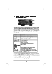
... P45XE-WiFiN Only) ASRock WiFi-802.11n module is an easy-to-use ASRock WiFi-802.11n module on this motherboard, please carefully read the document in the package for the detailed introduction and operation procedures. With ASRock WiFi-802.11n module, you can also read "ASRock ...WiFi-802.11n Module Operation Guide" in the following path of ASRock motherboard support CD: ..\ ASRock WiFi-802.11n \ Vista64_Vista_XP64_XP 16 IEEE 802.11n Data Rate -...
... P45XE-WiFiN Only) ASRock WiFi-802.11n module is an easy-to-use ASRock WiFi-802.11n module on this motherboard, please carefully read the document in the package for the detailed introduction and operation procedures. With ASRock WiFi-802.11n module, you can also read "ASRock ...WiFi-802.11n Module Operation Guide" in the following path of ASRock motherboard support CD: ..\ ASRock WiFi-802.11n \ Vista64_Vista_XP64_XP 16 IEEE 802.11n Data Rate -...
User Manual
Page 17
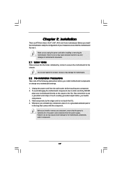
... you and damages to unplug the power cord before you install or remove any motherboard settings. 1. Failure to do so may damage the motherboard. 2.2 Pre-installation Precautions Take note of your motherboard directly on a grounded antistatic pad or in the bag that comes with the component... . Doing so may cause physical injuries to the chassis. Hold components by circles to secure the motherboard to you install motherboard components or change any component, ensure that the motherboard fits into the holes indicated by the edges and do so may cause severe damage to use ...
... you and damages to unplug the power cord before you install or remove any motherboard settings. 1. Failure to do so may damage the motherboard. 2.2 Pre-installation Precautions Take note of your motherboard directly on a grounded antistatic pad or in the bag that comes with the component... . Doing so may cause physical injuries to the chassis. Hold components by circles to secure the motherboard to you install motherboard components or change any component, ensure that the motherboard fits into the holes indicated by the edges and do so may cause severe damage to use ...
User Manual
Page 19
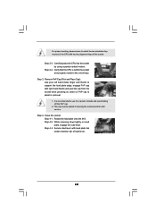
... to the orient keys. Carefully place the CPU into the socket by using a purely vertical motion. Step 2-4. This cap must be placed if returning the motherboard for after service.
... to the orient keys. Carefully place the CPU into the socket by using a purely vertical motion. Step 2-4. This cap must be placed if returning the motherboard for after service.
User Manual
Page 20
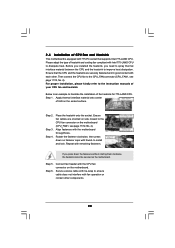
... Align fasteners with Intel 775-LAND CPU to dissipate heat. Step 6. Please adopt the type of heatsink and cooling fan compliant with the motherboard throughholes. Ensure that supports Intel 775-LAND CPU. Repeat with thumb to install and lock. Secure excess cable with tie-wrap to ensure ... side closest to the CPU fan connector on the socket surface. For proper installation, please kindly refer to the instruction manuals of IHS on the motherboard (CPU_FAN1, see page 11/12, No. 4). Below is equipped with fan operation or contact other . Step 3. Step 4. Place the heatsink ...
... Align fasteners with Intel 775-LAND CPU to dissipate heat. Step 6. Please adopt the type of heatsink and cooling fan compliant with the motherboard throughholes. Ensure that supports Intel 775-LAND CPU. Repeat with thumb to install and lock. Secure excess cable with tie-wrap to ensure ... side closest to the CPU fan connector on the socket surface. For proper installation, please kindly refer to the instruction manuals of IHS on the motherboard (CPU_FAN1, see page 11/12, No. 4). Below is equipped with fan operation or contact other . Step 3. Step 4. Place the heatsink ...
User Manual
Page 21
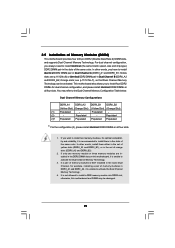
... the Dual Channel Memory Technology. 3. If only one memory module or three memory modules are installed in the slots of the same color. otherwise, this motherboard, it is unable to install a DDR memory module into DDR2 slot; 2.5 Installation of yellow slots (DDRII_A1 and DDRII_B1), or in Dual Channel B ... to install identical DDR2 DIMM pair in all four slots. Populated - In other words, install them in the DDR2 DIMM slots on this motherboard and DIMM may refer to install four DDR2 DIMMs for example, installing a pair of memory modules in the slots of orange slots (DDRII_A2 ...
... the Dual Channel Memory Technology. 3. If only one memory module or three memory modules are installed in the slots of the same color. otherwise, this motherboard, it is unable to install a DDR memory module into DDR2 slot; 2.5 Installation of yellow slots (DDRII_A1 and DDRII_B1), or in Dual Channel B ... to install identical DDR2 DIMM pair in all four slots. Populated - In other words, install them in the DDR2 DIMM slots on this motherboard and DIMM may refer to install four DDR2 DIMMs for example, installing a pair of memory modules in the slots of orange slots (DDRII_A2 ...
User Manual
Page 22
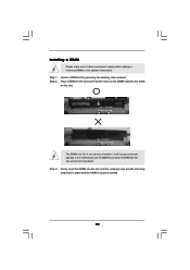
.... Step 2. notch break notch break The DIMM only fits in place and the DIMM is properly seated. 22 Installing a DIMM Please make sure to the motherboard and the DIMM if you force the DIMM into the slot until the retaining clips at incorrect orientation. Align a DIMM on the slot such that...
.... Step 2. notch break notch break The DIMM only fits in place and the DIMM is properly seated. 22 Installing a DIMM Please make sure to the motherboard and the DIMM if you force the DIMM into the slot until the retaining clips at incorrect orientation. Align a DIMM on the slot such that...
User Manual
Page 23
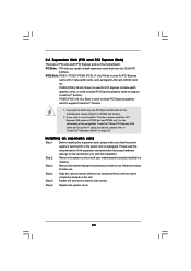
...necessary hardware settings for later use. Step 3. If you plan to install only one PCI Express VGA card on this motherboard, please install it on this motherboard. Step 2. Step 5. PCIE5 (PCIE x16 slot; Please read the documentation of the compatible CrossFireTM Mode PCI Express VGA...CrossFireTM Operation Guide" on the slot. Installing an expansion card Step 1. PCIE2 (PCIE x16 slot; Remove the system unit cover (if your motherboard is used to install PCI Express graphics cards to support CrossFireTM function. 1. 2.6 Expansion Slots (PCI and PCI Express Slots) There are ...
...necessary hardware settings for later use. Step 3. If you plan to install only one PCI Express VGA card on this motherboard, please install it on this motherboard. Step 2. Step 5. PCIE5 (PCIE x16 slot; Please read the documentation of the compatible CrossFireTM Mode PCI Express VGA...CrossFireTM Operation Guide" on the slot. Installing an expansion card Step 1. PCIE2 (PCIE x16 slot; Remove the system unit cover (if your motherboard is used to install PCI Express graphics cards to support CrossFireTM function. 1. 2.6 Expansion Slots (PCI and PCI Express Slots) There are ...
User Manual
Page 24
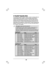
... Edition graphics card and a compatible standard Radeon (CrossFireTM Ready) graphics card from ATITM or any 3D application. 2.7 CrossFireTM Operation Guide This motherboard supports CrossFireTM feature. Combining a range of different operating modes with intelligent software design and an innovative interconnect mechanism, CrossFireTM enables the highest possible level of ...
... Edition graphics card and a compatible standard Radeon (CrossFireTM Ready) graphics card from ATITM or any 3D application. 2.7 CrossFireTM Operation Guide This motherboard supports CrossFireTM feature. Combining a range of different operating modes with intelligent software design and an innovative interconnect mechanism, CrossFireTM enables the highest possible level of ...
User Manual
Page 25
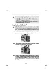
... Radeon graphics cards. (CrossFireTM Bridge is provided with the graphics card you pair a 12-pipe CrossFireTM Edition card with this motherboard. Install one Radeon graphics card to ATITM graphics card manuals for details.) 25 Step 3. Step 1. Enjoy the benefit of ... guide. Please refer to section "Expansion Slots". All three CrossFireTM components, a CrossFireTM Ready graphics card, a CrossFireTM Ready motherboard and a CrossFireTM Edition co-processor graphics card, must be installed correctly to section "Expansion Slots". Install one Radeon graphics card...
... Radeon graphics cards. (CrossFireTM Bridge is provided with the graphics card you pair a 12-pipe CrossFireTM Edition card with this motherboard. Install one Radeon graphics card to ATITM graphics card manuals for details.) 25 Step 3. Step 1. Enjoy the benefit of ... guide. Please refer to section "Expansion Slots". All three CrossFireTM components, a CrossFireTM Ready graphics card, a CrossFireTM Ready motherboard and a CrossFireTM Edition co-processor graphics card, must be installed correctly to section "Expansion Slots". Install one Radeon graphics card...
User Manual
Page 28
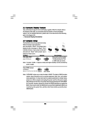
.../2 or USB wake up the system first, and then shut it requires 2 Amp and higher standby current provided by power supply. 2.8 Surround Display Feature This motherboard supports Surround Display upgrade. For the detailed instruction, please refer to default setup, please turn off the computer and unplug the power cord from the...
.../2 or USB wake up the system first, and then shut it requires 2 Amp and higher standby current provided by power supply. 2.8 Surround Display Feature This motherboard supports Surround Display upgrade. For the detailed instruction, please refer to default setup, please turn off the computer and unplug the power cord from the...
User Manual
Page 29
... and connectors are NOT jumpers. FDD connector (33-pin FLOPPY1) (see p.11/12 No. 9) PIN1 IDE1 connect the blue end to the motherboard connect the black end to the IDE devices 80-conductor ATA 66/100/133 cable Note: Please refer to 3.0 Gb/s data transfer rate. The... current SATAII interface allows up to the instruction of the motherboard! Please read "eSATAII Interface Introduction" on page 36 for internal storage device or be used for details about eSATAII and eSATAII installation procedures. 29...
... and connectors are NOT jumpers. FDD connector (33-pin FLOPPY1) (see p.11/12 No. 9) PIN1 IDE1 connect the blue end to the motherboard connect the black end to the IDE devices 80-conductor ATA 66/100/133 cable Note: Please refer to 3.0 Gb/s data transfer rate. The... current SATAII interface allows up to the instruction of the motherboard! Please read "eSATAII Interface Introduction" on page 36 for internal storage device or be used for details about eSATAII and eSATAII installation procedures. 29...


