User Manual
Page 12
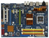
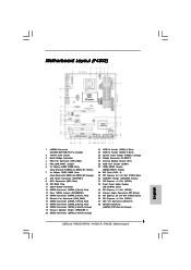
...2.0 T: USB2 B: USB3 Top: SIDE SPK Center: REAR SPK Bottom: CTR BASS USB 2.0 T: USB4 B: USB5 Intel P45 IDE1 ATX12V1 Chipset LAN PHY P45XE Top: LINE IN Center: FRONT Bottom: MIC IN PCIE1 RoHS PCI Express 2.0 AUDIO CODEC CD1 HD_AUDIO1 1 PCIE2 PCIE3 PCIE4 1 USB/WIFI PCIE5 8Mb BIOS... 23 22 21 20 19 18 17 16 15 30.5cm (12.0 in) 8 9 10 11 12 13 14 1 eSATAII Connector (eSATAII_BOTTOM (Port 5), Orange) 2 775-Pin CPU Socket 3 North Bridge Controller 4 CPU Fan Connector (CPU_FAN1) 5 PS2_USB_PWR1 Jumper 6 2 x 240-pin DDR2 DIMM Slots (Dual Channel A: DDRII_A1, DDRII_B1; Yellow) 7 2 ...
...2.0 T: USB2 B: USB3 Top: SIDE SPK Center: REAR SPK Bottom: CTR BASS USB 2.0 T: USB4 B: USB5 Intel P45 IDE1 ATX12V1 Chipset LAN PHY P45XE Top: LINE IN Center: FRONT Bottom: MIC IN PCIE1 RoHS PCI Express 2.0 AUDIO CODEC CD1 HD_AUDIO1 1 PCIE2 PCIE3 PCIE4 1 USB/WIFI PCIE5 8Mb BIOS... 23 22 21 20 19 18 17 16 15 30.5cm (12.0 in) 8 9 10 11 12 13 14 1 eSATAII Connector (eSATAII_BOTTOM (Port 5), Orange) 2 775-Pin CPU Socket 3 North Bridge Controller 4 CPU Fan Connector (CPU_FAN1) 5 PS2_USB_PWR1 Jumper 6 2 x 240-pin DDR2 DIMM Slots (Dual Channel A: DDRII_A1, DDRII_B1; Yellow) 7 2 ...

User Manual
Page 18
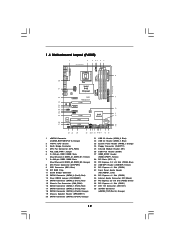
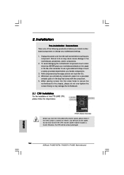
...orientation key notch orientation key notch Pin1 alignment key alignment key 775-LAND CPU 775-Pin Socket 18 black line black line Step 2-2. Step 1. Rotate the load lever to fully open position at approximately 135 degrees. Insert the 775-LAND CPU: Step 2-1. Otherwise, the CPU will be ...open position at approximately 100 degrees. Open the socket: Step 1-1. 2.3 CPU Installation For the installation of Intel 775-LAND CPU, please follow the steps below. 775-Pin Socket Overview Before you insert the 775-LAND CPU into the socket if above situation is any bent pin on the...
...orientation key notch orientation key notch Pin1 alignment key alignment key 775-LAND CPU 775-Pin Socket 18 black line black line Step 2-2. Step 1. Rotate the load lever to fully open position at approximately 135 degrees. Insert the 775-LAND CPU: Step 2-1. Otherwise, the CPU will be ...open position at approximately 100 degrees. Open the socket: Step 1-1. 2.3 CPU Installation For the installation of Intel 775-LAND CPU, please follow the steps below. 775-Pin Socket Overview Before you insert the 775-LAND CPU into the socket if above situation is any bent pin on the...
User Manual
Page 20
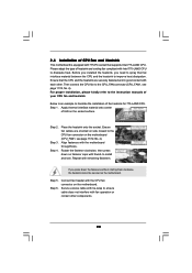
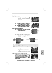
... Place the heatsink onto the socket. Ensure fan cables are securely fastened and in good contact with fan operation or contact other . Repeat with the CPU fan connector on the motherboard (CPU_FAN1, see page 11/12, No. 4). Step 6. Ensure that supports Intel 775-LAND CPU. Step 1. Step... header with remaining fasteners. Before you installed the heatsink, you press down on the motherboard. Step 2. Step 5. Below is equipped with 775-Pin socket that the CPU and the heatsink are oriented on side closest to the CPU fan connector on the motherboard. Align fasteners with Intel...
... Place the heatsink onto the socket. Ensure fan cables are securely fastened and in good contact with fan operation or contact other . Repeat with the CPU fan connector on the motherboard (CPU_FAN1, see page 11/12, No. 4). Step 6. Ensure that supports Intel 775-LAND CPU. Step 1. Step... header with remaining fasteners. Before you installed the heatsink, you press down on the motherboard. Step 2. Step 5. Below is equipped with 775-Pin socket that the CPU and the heatsink are oriented on side closest to the CPU fan connector on the motherboard. Align fasteners with Intel...
Quick Installation Guide
Page 2
... eSATAII Connector 19 SATAII Connector (SATAII_6 (Port5), Orange) (eSATAII_TOP (Port 4), Orange) 20 Chassis Speaker Header (SPEAKER 1) 2 ASRock P45XE-WiFiN / P45XE-R / P45XE Motherboard Motherboard Layout (P45XE-WiFiN / P45XE-R) English 1 eSATAII Connector 21 SATAII Connector (eSATAII_BOTTOM (Port 5), Orange) (SATAII_5 (Port4), Orange) 2 775-Pin CPU Socket 22 USB 2.0 Header (USB8_9, Blue) 3 North Bridge Controller 23 USB 2.0 Header (USB6_7, Blue) 4 CPU Fan...
... eSATAII Connector 19 SATAII Connector (SATAII_6 (Port5), Orange) (eSATAII_TOP (Port 4), Orange) 20 Chassis Speaker Header (SPEAKER 1) 2 ASRock P45XE-WiFiN / P45XE-R / P45XE Motherboard Motherboard Layout (P45XE-WiFiN / P45XE-R) English 1 eSATAII Connector 21 SATAII Connector (eSATAII_BOTTOM (Port 5), Orange) (SATAII_5 (Port4), Orange) 2 775-Pin CPU Socket 22 USB 2.0 Header (USB8_9, Blue) 3 North Bridge Controller 23 USB 2.0 Header (USB6_7, Blue) 4 CPU Fan...
Quick Installation Guide
Page 3
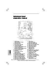
Yellow) 7 2 x 240-pin DDR2 DIMM Slots (Dual Channel B: DDRII_A2, DDRII_B2; Motherboard Layout (P45XE) 1 eSATAII Connector (eSATAII_BOTTOM (Port 5), Orange) 2 775-Pin CPU Socket 3 North Bridge Controller 4 CPU Fan Connector (CPU_FAN1) 5 PS2_USB_PWR1 Jumper 6 2 x 240-pin DDR2 DIMM Slots (Dual Channel A: DDRII_A1, DDRII_B1; Orange) 8 ATX Power Connector (ATXPWR1) 9 IDE1 ...) 35 PCI Express 2.0 x16 Slot (PCIE2, Green) 36 PCI Express x1 Slot (PCIE1) 37 ATX 12V Connector (ATX12V1) 38 eSATAII Connector (eSATAII_TOP (Port 4), Orange) 3 ASRock P45XE-WiFiN / P45XE-R / P45XE Motherboard English
Yellow) 7 2 x 240-pin DDR2 DIMM Slots (Dual Channel B: DDRII_A2, DDRII_B2; Motherboard Layout (P45XE) 1 eSATAII Connector (eSATAII_BOTTOM (Port 5), Orange) 2 775-Pin CPU Socket 3 North Bridge Controller 4 CPU Fan Connector (CPU_FAN1) 5 PS2_USB_PWR1 Jumper 6 2 x 240-pin DDR2 DIMM Slots (Dual Channel A: DDRII_A1, DDRII_B1; Orange) 8 ATX Power Connector (ATXPWR1) 9 IDE1 ...) 35 PCI Express 2.0 x16 Slot (PCIE2, Green) 36 PCI Express x1 Slot (PCIE1) 37 ATX 12V Connector (ATX12V1) 38 eSATAII Connector (eSATAII_TOP (Port 4), Orange) 3 ASRock P45XE-WiFiN / P45XE-R / P45XE Motherboard English
Quick Installation Guide
Page 14
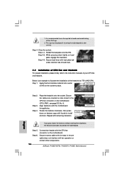
...to the motherboard, peripherals, and/or components. 2. Otherwise, the CPU will be seriously damaged. 14 ASRock P45XE-WiFiN / P45XE-R / P45XE Motherboard English Unplug the power cord from the wall socket before touching any bent pin on the carpet or the like. Failure to static electricity, NEVER place...CPU surface is unclean or if there is found. 2. Installation Pre-installation Precautions Take note of Intel 775-LAND CPU, please follow the steps below. 775-Pin Socket Overview Before you install motherboard components or change any component, place it on a grounded antstatic pad or...
...to the motherboard, peripherals, and/or components. 2. Otherwise, the CPU will be seriously damaged. 14 ASRock P45XE-WiFiN / P45XE-R / P45XE Motherboard English Unplug the power cord from the wall socket before touching any bent pin on the carpet or the like. Failure to static electricity, NEVER place...CPU surface is unclean or if there is found. 2. Installation Pre-installation Precautions Take note of Intel 775-LAND CPU, please follow the steps below. 775-Pin Socket Overview Before you install motherboard components or change any component, place it on a grounded antstatic pad or...
Quick Installation Guide
Page 15
... Locate Pin1 and the two orientation key notches. Step 3. Insert the 775-LAND CPU: Step 2-1. Pin1 orientation key notch orientation key notch Pin1 alignment key alignment key 775-LAND CPU 775-Pin Socket For proper inserting, please ensure to fully open position at approximately 100 degrees...up. Step 1. Verify that the CPU is within the socket and properly mated to assist in removal. 15 ASRock P45XE-WiFiN / P45XE-R / P45XE Motherboard English Orient the CPU with right hand thumb and peel the cap from the socket while pressing on the hook to fully open position at...
... Locate Pin1 and the two orientation key notches. Step 3. Insert the 775-LAND CPU: Step 2-1. Pin1 orientation key notch orientation key notch Pin1 alignment key alignment key 775-LAND CPU 775-Pin Socket For proper inserting, please ensure to fully open position at approximately 100 degrees...up. Step 1. Verify that the CPU is within the socket and properly mated to assist in removal. 15 ASRock P45XE-WiFiN / P45XE-R / P45XE Motherboard English Orient the CPU with right hand thumb and peel the cap from the socket while pressing on the hook to fully open position at...
Quick Installation Guide
Page 16
... them clockwise, the heatsink cannot be placed if returning the motherboard for 775-LAND CPU. Step 4-3. Place the heatsink onto the socket. Align fasteners with remaining fasteners. Secure excess cable with thumb to the... CPU fan connector on side closest to install and lock. If you press down lightly on the motherboard. Step 1. Rotate the load plate onto the IHS. Connect fan header with fan operation or contact other components. 16 ASRock P45XE-WiFiN / P45XE-R / P45XE...
... them clockwise, the heatsink cannot be placed if returning the motherboard for 775-LAND CPU. Step 4-3. Place the heatsink onto the socket. Align fasteners with remaining fasteners. Secure excess cable with thumb to the... CPU fan connector on side closest to install and lock. If you press down lightly on the motherboard. Step 1. Rotate the load plate onto the IHS. Connect fan header with fan operation or contact other components. 16 ASRock P45XE-WiFiN / P45XE-R / P45XE...