RAID Installation Guide
Page 2
... install SATA hard disks on SATA ports. 2 Guide to create RAID on this guide carefully according to Serial ATA (SATA) Hard Disks Installation of "User Manual" in this motherboard for internal storage devices. This section will guide you how to SATA Hard Disks Installation 1.1 Serial ATA (SATA) Hard Disks Installation Intel...
... install SATA hard disks on SATA ports. 2 Guide to create RAID on this guide carefully according to Serial ATA (SATA) Hard Disks Installation of "User Manual" in this motherboard for internal storage devices. This section will guide you how to SATA Hard Disks Installation 1.1 Serial ATA (SATA) Hard Disks Installation Intel...

User Manual
Page 1
P45TS-R / P45TS User Manual Version 1.0 Published July 2008 Copyright©2008 ASRock INC. All rights reserved. 1
P45TS-R / P45TS User Manual Version 1.0 Published July 2008 Copyright©2008 ASRock INC. All rights reserved. 1

User Manual
Page 2
... apply, see www.dtsc.ca.gov/hazardouswaste/perchlorate" ASRock Website: http://www.asrock.com 2 In no responsibility for any errors or omissions that may cause undesired operation. Disclaimer: Specifications and information contained in this manual are used only for identification or explanation and to...in California, USA, please follow the related regulations in Perchlorate Best Management Practices (BMP) regulations passed by ASRock. With respect to the contents of this manual, ASRock does not provide warranty of any kind, either expressed or implied, including but not limited to the ...
... apply, see www.dtsc.ca.gov/hazardouswaste/perchlorate" ASRock Website: http://www.asrock.com 2 In no responsibility for any errors or omissions that may cause undesired operation. Disclaimer: Specifications and information contained in this manual are used only for identification or explanation and to...in California, USA, please follow the related regulations in Perchlorate Best Management Practices (BMP) regulations passed by ASRock. With respect to the contents of this manual, ASRock does not provide warranty of any kind, either expressed or implied, including but not limited to the ...
User Manual
Page 5
... manual, chapter 1 and 2 contain introduction of the Support CD. In this motherboard, please visit our website for specific information about the model you for a 3.5-in Floppy Drive Two Serial ATA (SATA) Data Cables (Optional) One Serial ATA (SATA) HDD Power Cable (Optional) One "ASRock 1394_SPDIF I/O" I/O Panel Shield (P45TS-R) One "ASRock SPDIF I/O" I/O Panel Shield (P45TS) 5 www.asrock...
... manual, chapter 1 and 2 contain introduction of the Support CD. In this motherboard, please visit our website for specific information about the model you for a 3.5-in Floppy Drive Two Serial ATA (SATA) Data Cables (Optional) One Serial ATA (SATA) HDD Power Cable (Optional) One "ASRock 1394_SPDIF I/O" I/O Panel Shield (P45TS-R) One "ASRock SPDIF I/O" I/O Panel Shield (P45TS) 5 www.asrock...

User Manual
Page 18
... you installed the heatsink, you press down on the motherboard (CPU_FAN1, see page 11/12, No. 2). For proper installation, please kindly refer to the instruction manuals of the heatsink for 775-LAND CPU. Below is equipped with 775-Pin socket that the CPU and the heatsink are oriented on side closest...
... you installed the heatsink, you press down on the motherboard (CPU_FAN1, see page 11/12, No. 2). For proper installation, please kindly refer to the instruction manuals of the heatsink for 775-LAND CPU. Below is equipped with 775-Pin socket that the CPU and the heatsink are oriented on side closest...
User Manual
Page 26
.... 1. C. MIC_RET and OUT_RET are for AC'97 audio panel. You don't need to install your voice through front mic, please deselect "Mute" icon in our manual and chassis manual to connect them for HD audio panel only.
.... 1. C. MIC_RET and OUT_RET are for AC'97 audio panel. You don't need to install your voice through front mic, please deselect "Mute" icon in our manual and chassis manual to connect them for HD audio panel only.

User Manual
Page 29
... is an all-digital audio/video specification, which provides SPDIF audio output to HDMI VGA card, allows the system to the user manual of HDMI_SPDIF connectors on page 21. For the pin definition of the HDMI VGA card you install. Please choose the appropriate white end.... Step 2. white end (2-pin) (B) white end (3-pin) (C) Step 4. Please refer to the user manual of HDMI VGA card or other VGA card. Please refer to the VGA card user manual for detailed connection procedures. 2.9 HDMI_SPDIF Header Connection Guide HDMI (High-Definition Multi-media Interface) is equipped with...
... is an all-digital audio/video specification, which provides SPDIF audio output to HDMI VGA card, allows the system to the user manual of HDMI_SPDIF connectors on page 21. For the pin definition of the HDMI VGA card you install. Please choose the appropriate white end.... Step 2. white end (2-pin) (B) white end (3-pin) (C) Step 4. Please refer to the user manual of HDMI VGA card or other VGA card. Please refer to the VGA card user manual for detailed connection procedures. 2.9 HDMI_SPDIF Header Connection Guide HDMI (High-Definition Multi-media Interface) is equipped with...

User Manual
Page 36
...is definitely not able to support Hot Plug and will be processed. 2. Please make sure the SATA / SATAII driver is available on our website: www.asrock.com 2. The SATA / SATAII HDD, which are from our motherboard package. 5. A. 7-pin SATA data cable B. Even some SATA / SATAII HDDs...connector interfaces, the IDE 1x4-pin conventional power connector interface is indicated in RAID / AHCI mode. Make sure your dealer or HDD user manual. Please follow below instructions step by the chipset because of its limitation, the SATA / SATAII Hot Plug support information of attention, before ...
...is definitely not able to support Hot Plug and will be processed. 2. Please make sure the SATA / SATAII driver is available on our website: www.asrock.com 2. The SATA / SATAII HDD, which are from our motherboard package. 5. A. 7-pin SATA data cable B. Even some SATA / SATAII HDDs...connector interfaces, the IDE 1x4-pin conventional power connector interface is indicated in RAID / AHCI mode. Make sure your dealer or HDD user manual. Please follow below instructions step by the chipset because of its limitation, the SATA / SATAII Hot Plug support information of attention, before ...
User Manual
Page 44
... setup to set the selection from [Auto] to fixed PCI / PCIE buses. Therefore, CPU FSB is untied during overclocking, FSB enjoys better margin due to [Manual]. 2.18 Untied Overclocking Technology This motherboard supports Untied Overclocking Technology, which means during overclocking, but PCI / PCIE buses are in the fixed mode so that...
... setup to set the selection from [Auto] to fixed PCI / PCIE buses. Therefore, CPU FSB is untied during overclocking, FSB enjoys better margin due to [Manual]. 2.18 Untied Overclocking Technology This motherboard supports Untied Overclocking Technology, which means during overclocking, but PCI / PCIE buses are in the fixed mode so that...

User Manual
Page 50
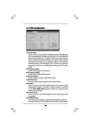
Configuration options: [Auto], [Manual], [I .O.T.] (Intelligent Overclocking Technology), you are allowed to adjust the means of DRAM clocks for TRP. Please refer to page 44 for the details of DRAM ... tRP This controls the number of memory accessing. PCIE Frequency (MHz) Use this motherboard. If you adopt on the CPU and memory module you select [Manual], Untied Overclocking function is [Auto]. Standard Memory Info : 5-5-5-15-36-5-3-3-3 DRAM tCL Use this option to [24]. DRAM tRAS This controls the number of DRAM...
Configuration options: [Auto], [Manual], [I .O.T.] (Intelligent Overclocking Technology), you are allowed to adjust the means of DRAM clocks for TRP. Please refer to page 44 for the details of DRAM ... tRP This controls the number of memory accessing. PCIE Frequency (MHz) Use this motherboard. If you adopt on the CPU and memory module you select [Manual], Untied Overclocking function is [Auto]. Standard Memory Info : 5-5-5-15-36-5-3-3-3 DRAM tCL Use this option to [24]. DRAM tRAS This controls the number of DRAM...

User Manual
Page 51
... [Highest]. Configuration options: [Auto], [0.67 x Vtt], [0.65 x Vtt], [0.63 x Vtt] and [0.615 x Vtt]. PLL Voltage Use this to select PLL Voltage. Configuration options: [Auto] and [Manual]. The default value of this feature is [Auto]. SB 1.1V Voltage Use this to select SB 1.1V Voltage. Configuration options: [Auto], [Low], [Middle], [High] and...
... [Highest]. Configuration options: [Auto], [0.67 x Vtt], [0.65 x Vtt], [0.63 x Vtt] and [0.615 x Vtt]. PLL Voltage Use this to select PLL Voltage. Configuration options: [Auto] and [Manual]. The default value of this feature is [Auto]. SB 1.1V Voltage Use this to select SB 1.1V Voltage. Configuration options: [Auto], [Low], [Middle], [High] and...
User Manual
Page 52
... (Min: 06, Max: 12) 12 [12] Enhanced Halt State Intel (R) Virtualization tech. Overclock Mode Use this motherboard. Configuration options: [Auto], [Manual], [I .O.T.] (Intelligent Overclocking Technology), you are allowed to allow you select [Manual], Untied Overclocking function is [Auto]. Spread Spectrum This item should always be [Auto] for the details of this option to...
... (Min: 06, Max: 12) 12 [12] Enhanced Halt State Intel (R) Virtualization tech. Overclock Mode Use this motherboard. Configuration options: [Auto], [Manual], [I .O.T.] (Intelligent Overclocking Technology), you are allowed to allow you select [Manual], Untied Overclocking function is [Auto]. Spread Spectrum This item should always be [Auto] for the details of this option to...

User Manual
Page 56
...Core Voltage. Configuration options: Configuration options: [Auto], [0] to [30]. CPU Voltage Use this feature is [Auto]. 56 Configuration options: [Auto] and [Manual]. If you plan to use this feature is [Auto]. OnBoard 1394 This option is [PCI]. The default value of DRAM clocks for...The default value is for CH1 TRD Phase Adjust. Configuration options for the onboard HD Audio Front Panel. The default value of DRAM clocks for P45TS-R only. Primary Graphics Adapter This allows you to select [PCI] or [PCI Express] as the boot graphic adapter priority. The default value...
...Core Voltage. Configuration options: Configuration options: [Auto], [0] to [30]. CPU Voltage Use this feature is [Auto]. 56 Configuration options: [Auto] and [Manual]. If you plan to use this feature is [Auto]. OnBoard 1394 This option is [PCI]. The default value of DRAM clocks for...The default value is for CH1 TRD Phase Adjust. Configuration options for the onboard HD Audio Front Panel. The default value of DRAM clocks for P45TS-R only. Primary Graphics Adapter This allows you to select [PCI] or [PCI Express] as the boot graphic adapter priority. The default value...
Quick Installation Guide
Page 6
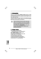
... ASRock P45RTS-R / P45TS motherboard, a reliable motherboard produced under ASRock's consistently stringent quality control. www.asrock.com/support/index.asp 1.1 Package Contents ASRock P45RTS-R / P45TS Motherboard (ATX Form Factor: 12.0-in x 9.6-in Floppy Drive Two Serial ATA (SATA) Data Cables (Optional) One Serial ATA (SATA) HDD Power Cable (Optional) One "ASRock 1394_SPDIF I/O" I/O Panel Shield (P45TS-R) One "ASRock SPDIF I/O" I/O Panel Shield (P45TS) 6 ASRock P45TS-R / P45TS...
... ASRock P45RTS-R / P45TS motherboard, a reliable motherboard produced under ASRock's consistently stringent quality control. www.asrock.com/support/index.asp 1.1 Package Contents ASRock P45RTS-R / P45TS Motherboard (ATX Form Factor: 12.0-in x 9.6-in Floppy Drive Two Serial ATA (SATA) Data Cables (Optional) One Serial ATA (SATA) HDD Power Cable (Optional) One "ASRock 1394_SPDIF I/O" I/O Panel Shield (P45TS-R) One "ASRock SPDIF I/O" I/O Panel Shield (P45TS) 6 ASRock P45TS-R / P45TS...
Quick Installation Guide
Page 10
... interface, the external SATAII specification. About the setting of "Hyper Threading Technology", please check page 53 of "User Manual" in this situation, please adopt DDR3 1333 memory modules on page 33 of wireless network connectivity. CPU FSB Frequency Memory... This motherboard supports native FSB1600/1333/1066/800 MHz. Please check the table on page 25 for details. 4. ASRock website http://www.asrock.com 10 ASRock P45TS-R / P45TS Motherboard English For normal operation, you adopt may be overclocked to SATAII connector, please read "eSATAII Interface Introduction" on...
... interface, the external SATAII specification. About the setting of "Hyper Threading Technology", please check page 53 of "User Manual" in this situation, please adopt DDR3 1333 memory modules on page 33 of wireless network connectivity. CPU FSB Frequency Memory... This motherboard supports native FSB1600/1333/1066/800 MHz. Please check the table on page 25 for details. 4. ASRock website http://www.asrock.com 10 ASRock P45TS-R / P45TS Motherboard English For normal operation, you adopt may be overclocked to SATAII connector, please read "eSATAII Interface Introduction" on...
Quick Installation Guide
Page 11
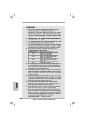
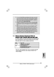
... please follow below table for Windows® VistaTM Premium 2008 logo. English 11 ASRock P45TS-R / P45TS Motherboard 12. Frequencies other than the recommended CPU bus frequencies may cause the instability of ASRock OC Tuner. Although this motherboard and plan to get the best system performance under... Windows® 2000 OS. ASRock website: http://www.asrock.com 13. To improve heat dissipation, remember to qualify for minimum hardware requirements. Please refer to page 58 of "User Manual" in order to spray thermal grease between the CPU ...
... please follow below table for Windows® VistaTM Premium 2008 logo. English 11 ASRock P45TS-R / P45TS Motherboard 12. Frequencies other than the recommended CPU bus frequencies may cause the instability of ASRock OC Tuner. Although this motherboard and plan to get the best system performance under... Windows® 2000 OS. ASRock website: http://www.asrock.com 13. To improve heat dissipation, remember to qualify for minimum hardware requirements. Please refer to page 58 of "User Manual" in order to spray thermal grease between the CPU ...
Quick Installation Guide
Page 14
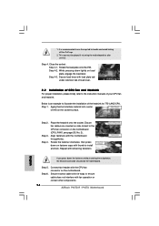
... lever. 2.2 Installation of CPU Fan and Heatsink For proper installation, please kindly refer to install and lock. Connect fan header with thumb to the instruction manuals of the heatsink for after service. It is an example to handle and avoid kicking off the PnP cap. 2. Close the socket: Step 4-1. While pressing... press down lightly on the motherboard. Step 5. Rotate the load plate onto the IHS. Step 4-2. Align fasteners with fan operation or contact other components. 14 ASRock P45TS-R / P45TS Motherboard English Step 3. 1.
... lever. 2.2 Installation of CPU Fan and Heatsink For proper installation, please kindly refer to install and lock. Connect fan header with thumb to the instruction manuals of the heatsink for after service. It is an example to handle and avoid kicking off the PnP cap. 2. Close the socket: Step 4-1. While pressing... press down lightly on the motherboard. Step 5. Rotate the load plate onto the IHS. Step 4-2. Align fasteners with fan operation or contact other components. 14 ASRock P45TS-R / P45TS Motherboard English Step 3. 1.
Quick Installation Guide
Page 22
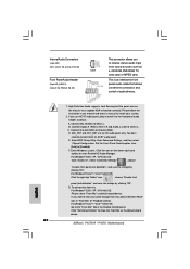
...that allows convenient connection and control of "Playback" portion. Connect Mic_IN (MIC) to the front panel audio header as the default record device. 22 ASRock P45TS-R / P45TS Motherboard English Enter Windows system. MIC_RET and OUT_RET are for AC'97 audio panel. You don't need to install your voice through front mic, ... clicking "OK". To activate the front mic. For Windows® VistaTM / VistaTM 64-bit OS: Go to the "Front Mic" Tab in our manual and chassis manual to connect them for HD audio panel only. If you use AC'97 audio panel, please install it to MIC2_L.
...that allows convenient connection and control of "Playback" portion. Connect Mic_IN (MIC) to the front panel audio header as the default record device. 22 ASRock P45TS-R / P45TS Motherboard English Enter Windows system. MIC_RET and OUT_RET are for AC'97 audio panel. You don't need to install your voice through front mic, ... clicking "OK". To activate the front mic. For Windows® VistaTM / VistaTM 64-bit OS: Go to the "Front Mic" Tab in our manual and chassis manual to connect them for HD audio panel only. If you use AC'97 audio panel, please install it to MIC2_L.

Quick Installation Guide
Page 25
Please refer to page 27 to 29 for detailed information of "User Manual" in BIOS setup to the eSATAII ports only when the system is supported with eSATAII devices. If you can insert or remove your eSATAII ...interface between any compatible digital audio/video source, such as a set "Configure SATAII as a digital television (DTV). SATAII connector SATAII_6 (Port5) eSATAII connector (eSATAII) 25 ASRock P45TS-R / P45TS Motherboard English This motherboard is an all-digital audio/video specification, which provides SPDIF audio output to HDMI VGA card, allows the system to install...
Please refer to page 27 to 29 for detailed information of "User Manual" in BIOS setup to the eSATAII ports only when the system is supported with eSATAII devices. If you can insert or remove your eSATAII ...interface between any compatible digital audio/video source, such as a set "Configure SATAII as a digital television (DTV). SATAII connector SATAII_6 (Port5) eSATAII connector (eSATAII) 25 ASRock P45TS-R / P45TS Motherboard English This motherboard is an all-digital audio/video specification, which provides SPDIF audio output to HDMI VGA card, allows the system to install...
Quick Installation Guide
Page 30
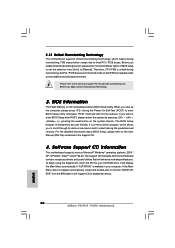
... motherboard contains necessary drivers and useful utilities that FSB can operate under a more stable overclocking environment. It is designed to the User Manual (PDF file) contained in the Support CD to fixed PCI / PCIE buses. For the detailed information about BIOS Setup, please refer... on page 9 for the possible overclocking risk before you wish to [Manual]. Before you start up the computer, please press during overclocking, FSB enjoys better margin due to display the menus. 30 ASRock P45TS-R / P45TS Motherboard English If the Main Menu does not appear automatically, locate and...
... motherboard contains necessary drivers and useful utilities that FSB can operate under a more stable overclocking environment. It is designed to the User Manual (PDF file) contained in the Support CD to fixed PCI / PCIE buses. For the detailed information about BIOS Setup, please refer... on page 9 for the possible overclocking risk before you wish to [Manual]. Before you start up the computer, please press during overclocking, FSB enjoys better margin due to display the menus. 30 ASRock P45TS-R / P45TS Motherboard English If the Main Menu does not appear automatically, locate and...
