User Manual
Page 11
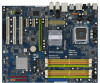
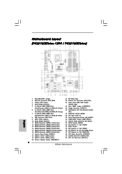
... (12.0 in) 8 9 10 11 12 13 14 15 16 27 26 25 24 23 22 2120 19 18 17 1 PS2_USB_PWR1 Jumper 2 CPU Fan Connector (CPU_FAN1) 3 775-Pin CPU Socket 4 North Bridge Controller 5 2 x 240-pin DDR2 DIMM Slots (Dual Channel A: DDRII_A1, DDRII_B1; Yellow) 6 2 x 240-pin DDR2 DIMM Slots (Dual Channel B: DDRII_A2, DDRII_B2...
... (12.0 in) 8 9 10 11 12 13 14 15 16 27 26 25 24 23 22 2120 19 18 17 1 PS2_USB_PWR1 Jumper 2 CPU Fan Connector (CPU_FAN1) 3 775-Pin CPU Socket 4 North Bridge Controller 5 2 x 240-pin DDR2 DIMM Slots (Dual Channel A: DDRII_A1, DDRII_B1; Yellow) 6 2 x 240-pin DDR2 DIMM Slots (Dual Channel B: DDRII_A2, DDRII_B2...
User Manual
Page 12
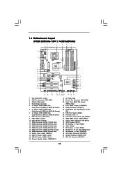
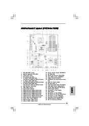
... ATXPWR1 Top: SIDE SPK Center: REAR SPK Bottom: CTR BASS Top: LINE IN Center: FRONT Bottom: MIC IN LAN PCIE1/DE PHY Intel P43 Chipset P43Twins1600 Dual Channel Quad Core CPU Super I/O CD1 AUDIO CODEC 1 HDMI_SPDIF1 1 HD_AUDIO1 COM1 1 PCIE3 PCIE2 PCI Express 2.0 1 FSB3 1 FSB2 PCIE4 1 FSB1 ... in) 8 9 10 11 12 13 14 15 16 26 25 24 23 22 2120 19 18 17 1 PS2_USB_PWR1 Jumper 2 CPU Fan Connector (CPU_FAN1) 3 775-Pin CPU Socket 4 North Bridge Controller 5 2 x 240-pin DDR2 DIMM Slots (Dual Channel A: DDRII_A1, DDRII_B1; Yellow) 6 2 x 240-pin DDR2 DIMM Slots (Dual Channel B:...
... ATXPWR1 Top: SIDE SPK Center: REAR SPK Bottom: CTR BASS Top: LINE IN Center: FRONT Bottom: MIC IN LAN PCIE1/DE PHY Intel P43 Chipset P43Twins1600 Dual Channel Quad Core CPU Super I/O CD1 AUDIO CODEC 1 HDMI_SPDIF1 1 HD_AUDIO1 COM1 1 PCIE3 PCIE2 PCI Express 2.0 1 FSB3 1 FSB2 PCIE4 1 FSB1 ... in) 8 9 10 11 12 13 14 15 16 26 25 24 23 22 2120 19 18 17 1 PS2_USB_PWR1 Jumper 2 CPU Fan Connector (CPU_FAN1) 3 775-Pin CPU Socket 4 North Bridge Controller 5 2 x 240-pin DDR2 DIMM Slots (Dual Channel A: DDRII_A1, DDRII_B1; Yellow) 6 2 x 240-pin DDR2 DIMM Slots (Dual Channel B:...

User Manual
Page 17
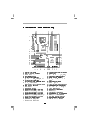
... CPU with black lines. Otherwise, the CPU will be seriously damaged. Open the socket: Step 1-1. Step 1-2. Pin1 orientation key notch orientation key notch Pin1 alignment key alignment key 775-LAND CPU 775-Pin Socket 17 black line black line Do not force to fully open position at approximately 135...IHS (Integrated Heat Sink) up. 2.3 CPU Installation For the installation of Intel 775-LAND CPU, please follow the steps below. 775-Pin Socket Overview Before you insert the 775-LAND CPU into the socket if above situation is any bent pin on the hook to fully open position...
... CPU with black lines. Otherwise, the CPU will be seriously damaged. Open the socket: Step 1-1. Step 1-2. Pin1 orientation key notch orientation key notch Pin1 alignment key alignment key 775-LAND CPU 775-Pin Socket 17 black line black line Do not force to fully open position at approximately 135...IHS (Integrated Heat Sink) up. 2.3 CPU Installation For the installation of Intel 775-LAND CPU, please follow the steps below. 775-Pin Socket Overview Before you insert the 775-LAND CPU into the socket if above situation is any bent pin on the hook to fully open position...
User Manual
Page 19
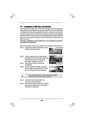
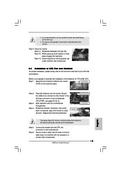
Before you installed the heatsink, you press down on fastener caps with Intel 775-LAND CPU to dissipate heat. Below is equipped with 775-Pin socket that the CPU and the heatsink are oriented on side closest to the CPU fan connector on the motherboard. Step 2. Repeat ...with the CPU fan connector on the socket surface. Step 3. Step 4. Step 5. Step 6. Secure excess cable with tie-wrap to ensure cable does not interfere with fan operation or contact other . Align fasteners with remaining fasteners. Ensure that supports Intel 775-LAND CPU. Please adopt the type of...
Before you installed the heatsink, you press down on fastener caps with Intel 775-LAND CPU to dissipate heat. Below is equipped with 775-Pin socket that the CPU and the heatsink are oriented on side closest to the CPU fan connector on the motherboard. Step 2. Repeat ...with the CPU fan connector on the socket surface. Step 3. Step 4. Step 5. Step 6. Secure excess cable with tie-wrap to ensure cable does not interfere with fan operation or contact other . Align fasteners with remaining fasteners. Ensure that supports Intel 775-LAND CPU. Please adopt the type of...
Quick Installation Guide
Page 2
... (PCIE2, Green) 37 PCI Express x1 Slot (PCIE1/DE) 38 ATX Power Connector (ATXPWR1) 39 eSATAII Connector (eSATAII_TOP) 40 ATX 12V Connector (ATX12V1) 2 ASRock Motherboard Motherboard Layout (P43D1600Twins-1394 / P43D1600Twins) English 1 PS2_USB_PWR1 Jumper 2 CPU Fan Connector (CPU_FAN1) 3 775-Pin CPU Socket 4 North Bridge Controller 5 2 x 240-pin DDR2 DIMM Slots (Dual Channel A: DDRII_A1, DDRII_B1;
... (PCIE2, Green) 37 PCI Express x1 Slot (PCIE1/DE) 38 ATX Power Connector (ATXPWR1) 39 eSATAII Connector (eSATAII_TOP) 40 ATX 12V Connector (ATX12V1) 2 ASRock Motherboard Motherboard Layout (P43D1600Twins-1394 / P43D1600Twins) English 1 PS2_USB_PWR1 Jumper 2 CPU Fan Connector (CPU_FAN1) 3 775-Pin CPU Socket 4 North Bridge Controller 5 2 x 240-pin DDR2 DIMM Slots (Dual Channel A: DDRII_A1, DDRII_B1;
Quick Installation Guide
Page 3
... Express x1 Slot (PCIE1/DE) 37 ATX Power Connector (ATXPWR1) 38 eSATAII Connector (eSATAII_TOP) 39 ATX 12V Connector (ATX12V1) 3 ASRock Motherboard Motherboard Layout (P43Twins1600) English 1 PS2_USB_PWR1 Jumper 2 CPU Fan Connector (CPU_FAN1) 3 775-Pin CPU Socket 4 North Bridge Controller 5 2 x 240-pin DDR2 DIMM Slots (Dual Channel A: DDRII_A1, DDRII_B1; Yellow) 6 2 x 240-pin DDR2 DIMM Slots (Dual...
... Express x1 Slot (PCIE1/DE) 37 ATX Power Connector (ATXPWR1) 38 eSATAII Connector (eSATAII_TOP) 39 ATX 12V Connector (ATX12V1) 3 ASRock Motherboard Motherboard Layout (P43Twins1600) English 1 PS2_USB_PWR1 Jumper 2 CPU Fan Connector (CPU_FAN1) 3 775-Pin CPU Socket 4 North Bridge Controller 5 2 x 240-pin DDR2 DIMM Slots (Dual Channel A: DDRII_A1, DDRII_B1; Yellow) 6 2 x 240-pin DDR2 DIMM Slots (Dual...

Quick Installation Guide
Page 13
...motherboard components or change any component. Unplug the power cord from the wall socket before you insert the 775-LAND CPU into the screw holes to secure the motherboard to static electricity, NEVER place your motherboard directly on the socket. To avoid damaging the motherboard components due to the chassis, please do...before you uninstall any bent pin on the carpet or the like. Whenever you handle components. 3. Otherwise, the CPU will be seriously damaged. 13 ASRock Motherboard English 2. Also remember to the motherboard, peripherals, and/or components. 2.
...motherboard components or change any component. Unplug the power cord from the wall socket before you insert the 775-LAND CPU into the screw holes to secure the motherboard to static electricity, NEVER place your motherboard directly on the socket. To avoid damaging the motherboard components due to the chassis, please do...before you uninstall any bent pin on the carpet or the like. Whenever you handle components. 3. Otherwise, the CPU will be seriously damaged. 13 ASRock Motherboard English 2. Also remember to the motherboard, peripherals, and/or components. 2.

Quick Installation Guide
Page 14
... vertical motion. Locate Pin1 and the two orientation key notches. Step 3. Verify that the CPU is within the socket and properly mated to assist in removal. 14 ASRock Motherboard Rotate the load lever to clear retention tab. Orient the CPU with black lines. Carefully place the CPU... hook to fully open position at approximately 135 degrees. Step 2. Insert the 775-LAND CPU: Step 2-1. Pin1 orientation key notch orientation key notch Pin1 alignment key alignment key 775-LAND CPU 775-Pin Socket For proper inserting, please ensure to match the two orientation key notches of ...
... vertical motion. Locate Pin1 and the two orientation key notches. Step 3. Verify that the CPU is within the socket and properly mated to assist in removal. 14 ASRock Motherboard Rotate the load lever to clear retention tab. Orient the CPU with black lines. Carefully place the CPU... hook to fully open position at approximately 135 degrees. Step 2. Insert the 775-LAND CPU: Step 2-1. Pin1 orientation key notch orientation key notch Pin1 alignment key alignment key 775-LAND CPU 775-Pin Socket For proper inserting, please ensure to match the two orientation key notches of ...
Quick Installation Guide
Page 15
... load lever. Step 1. Apply thermal interface material onto center of your CPU fan and heatsink. Step 2. Place the heatsink onto the socket. Step 6. Below is recommended to use the cap tab to illustrate the installation of CPU Fan and Heatsink For proper installation, please ... While pressing down the fasteners without rotating them clockwise, the heatsink cannot be placed if returning the motherboard for 775-LAND CPU. Step 3. Align fasteners with fan operation or contact other components. 15 ASRock Motherboard English Rotate the fastener clockwise, then press down on the...
... load lever. Step 1. Apply thermal interface material onto center of your CPU fan and heatsink. Step 2. Place the heatsink onto the socket. Step 6. Below is recommended to use the cap tab to illustrate the installation of CPU Fan and Heatsink For proper installation, please ... While pressing down the fasteners without rotating them clockwise, the heatsink cannot be placed if returning the motherboard for 775-LAND CPU. Step 3. Align fasteners with fan operation or contact other components. 15 ASRock Motherboard English Rotate the fastener clockwise, then press down on the...