User Manual
Page 2
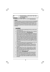
...any form or by any language, in this manual may or may apply, see www.dtsc.ca.gov/hazardouswaste/perchlorate" ASRock Website: http://www.asrock.com 2 "Perchlorate Material-special handling may not be registered trademarks or copyrights of their respective companies, and are furnished ... commitment by the California Legislature. With respect to the contents of this manual, ASRock does not provide warranty of the FCC Rules. CALIFORNIA, USA ONLY The Lithium battery adopted on this motherboard contains Perchlorate, a toxic substance controlled in this device must accept any kind, ...
...any form or by any language, in this manual may or may apply, see www.dtsc.ca.gov/hazardouswaste/perchlorate" ASRock Website: http://www.asrock.com 2 "Perchlorate Material-special handling may not be registered trademarks or copyrights of their respective companies, and are furnished ... commitment by the California Legislature. With respect to the contents of this manual, ASRock does not provide warranty of the FCC Rules. CALIFORNIA, USA ONLY The Lithium battery adopted on this motherboard contains Perchlorate, a toxic substance controlled in this device must accept any kind, ...
User Manual
Page 3
... Functions 28 2.14 Installing Windows® 7 / 7 64-bit / VistaTM / VistaTM 64-bit With RAID Functions 28 2.15 Untied Overclocking Technology 29 3 . Introduction 5 1.1 Package Contents 5 1.2 Specifications 6 1.3 Motherboard Layout (N68-VGS3 FX / N68-VS3 FX 11 1.4 I/O Panel (N68-VGS3 FX 12 1.5 I/O Panel (N68-VS3 FX 13 2 .
... Functions 28 2.14 Installing Windows® 7 / 7 64-bit / VistaTM / VistaTM 64-bit With RAID Functions 28 2.15 Untied Overclocking Technology 29 3 . Introduction 5 1.1 Package Contents 5 1.2 Specifications 6 1.3 Motherboard Layout (N68-VGS3 FX / N68-VS3 FX 11 1.4 I/O Panel (N68-VGS3 FX 12 1.5 I/O Panel (N68-VS3 FX 13 2 .
User Manual
Page 5
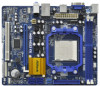
... the hardware installation. In this motherboard, please visit our website for purchasing ASRock N68-VGS3 FX / N68-VS3 FX motherboard, a reliable motherboard produced under ASRock's consistently stringent quality control. www.asrock.com/support/index.asp 1.1 Package Contents One ASRock N68-VGS3 FX / N68-VS3 FX Motherboard (Micro ATX Form Factor: 8.5-in x 7.0-in, 21.6 cm x 17.8 cm) One ASRock N68-VGS3 FX / N68-VS3 FX Quick Installation Guide One ASRock N68-VGS3 FX / N68-VS3 FX Support CD Two Serial ATA...
... the hardware installation. In this motherboard, please visit our website for purchasing ASRock N68-VGS3 FX / N68-VS3 FX motherboard, a reliable motherboard produced under ASRock's consistently stringent quality control. www.asrock.com/support/index.asp 1.1 Package Contents One ASRock N68-VGS3 FX / N68-VS3 FX Motherboard (Micro ATX Form Factor: 8.5-in x 7.0-in, 21.6 cm x 17.8 cm) One ASRock N68-VGS3 FX / N68-VS3 FX Quick Installation Guide One ASRock N68-VGS3 FX / N68-VS3 FX Support CD Two Serial ATA...
User Manual
Page 8
...system usage under Windows® 7 / VistaTM / XP. This motherboard supports CPU up to change. ASRock UCC (Unlock CPU Core) feature simplifies AMD CPU activation. This motherboard supports Untied Overclocking Technology. ASRock website http://www.asrock.com 7. OS - Please be malfunctioned. 4. Whether 1600MHz memory ..., you adopt. As long as a simple switch of the BIOS option "ASRock UCC", you can also increase L3 cache size up to use the external graphics card. 2. This motherboard supports Dual Channel Memory Technology. CAUTION! 1. When UCC feature is subject to...
...system usage under Windows® 7 / VistaTM / XP. This motherboard supports CPU up to change. ASRock UCC (Unlock CPU Core) feature simplifies AMD CPU activation. This motherboard supports Untied Overclocking Technology. ASRock website http://www.asrock.com 7. OS - Please be malfunctioned. 4. Whether 1600MHz memory ..., you adopt. As long as a simple switch of the BIOS option "ASRock UCC", you can also increase L3 cache size up to use the external graphics card. 2. This motherboard supports Dual Channel Memory Technology. CAUTION! 1. When UCC feature is subject to...
User Manual
Page 9
Before installing SATAII hard disk to SATAII connector, please read the "SATAII Hard Disk Setup Guide" on the same motherboard. 9 Please visit our website for the operation procedures of overclocking settings. With this tool and save the new BIOS file ...floppy disk or hard drive, then you can update your overclocking record under Windows® environment. In other complicated flash utility. ASRock website: http://www.asrock.com 12. Just launch this utility, you to update system BIOS without sacrificing computing performance. Your friends then can press key ...
Before installing SATAII hard disk to SATAII connector, please read the "SATAII Hard Disk Setup Guide" on the same motherboard. 9 Please visit our website for the operation procedures of overclocking settings. With this tool and save the new BIOS file ...floppy disk or hard drive, then you can update your overclocking record under Windows® environment. In other complicated flash utility. ASRock website: http://www.asrock.com 12. Just launch this utility, you to update system BIOS without sacrificing computing performance. Your friends then can press key ...
User Manual
Page 10
... video and download files simultaneously. ASRock APP Charger allows you to 40% faster than the recommended CPU bus frequencies may depend on -the-go. Traffic Shaping: You can boost USB storage device performance. Although this motherboard offers stepless control, it can ...simultaneously and even supports continuous charging when your Apple devices, such as iPhone/iPod/iPad Touch, ASRock has prepared a wonderful solution for a more personal Internet experience. ASRock motherboards are currently transferring. 18. 14. Simply installing the APP Charger driver, it makes your iPhone...
... video and download files simultaneously. ASRock APP Charger allows you to 40% faster than the recommended CPU bus frequencies may depend on -the-go. Traffic Shaping: You can boost USB storage device performance. Although this motherboard offers stepless control, it can ...simultaneously and even supports continuous charging when your Apple devices, such as iPhone/iPod/iPad Touch, ASRock has prepared a wonderful solution for a more personal Internet experience. ASRock motherboards are currently transferring. 18. 14. Simply installing the APP Charger driver, it makes your iPhone...
User Manual
Page 11
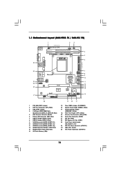
... (PCIE1) 23 Front Panel Audio Header (HD_AUDIO1, Lime) 24 ATX 12V Power Connector (ATX12V1) 25 AM3 CPU Socket 26 ATX Power Connector (ATXPWR1) 11 1.3 Motherboard Layout (N68-VGS3 FX / N68-VS3 FX) 26 USB 2.0 T: USB2 B: USB3 VGA1 PS2 Mouse PS2 Keyboard 1 2 3 17.8cm (7.0-in) Support 8-Core CPU 1 PS2_USB_PWR1 CPU_FAN1 1 USB_PWR2 DDR3_B1 (64 bit, 240-FpSin Bm8od0u0le...
... (PCIE1) 23 Front Panel Audio Header (HD_AUDIO1, Lime) 24 ATX 12V Power Connector (ATX12V1) 25 AM3 CPU Socket 26 ATX Power Connector (ATXPWR1) 11 1.3 Motherboard Layout (N68-VGS3 FX / N68-VS3 FX) 26 USB 2.0 T: USB2 B: USB3 VGA1 PS2 Mouse PS2 Keyboard 1 2 3 17.8cm (7.0-in) Support 8-Core CPU 1 PS2_USB_PWR1 CPU_FAN1 1 USB_PWR2 DDR3_B1 (64 bit, 240-FpSin Bm8od0u0le...
User Manual
Page 14
...placing screws into it on the carpet or the like. To avoid damaging the motherboard components due to the motherboard, peripherals, and/or components. 1. Whenever you install or remove any component. 2. Before you uninstall any motherboard settings. Unplug the power cord from the power supply. Hold components by the edges... and do so may damage the motherboard. 14 Pre-installation Precautions Take note of the following precautions before you handle components. 3. Failure to do not touch the ICs. 4....
...placing screws into it on the carpet or the like. To avoid damaging the motherboard components due to the motherboard, peripherals, and/or components. 1. Whenever you install or remove any component. 2. Before you uninstall any motherboard settings. Unplug the power cord from the power supply. Hold components by the edges... and do so may damage the motherboard. 14 Pre-installation Precautions Take note of the following precautions before you handle components. 3. Failure to do not touch the ICs. 4....
User Manual
Page 15
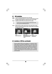
... triangle. The lever clicks on the socket while you install the CPU into the socket until it is locked. Carefully insert the CPU into this motherboard, it fits in one correct orientation. Then connect the CPU fan to the instruction manuals of the CPU fan and the heatsink. 15 Step 3. Lever...
... triangle. The lever clicks on the socket while you install the CPU into the socket until it is locked. Carefully insert the CPU into this motherboard, it fits in one correct orientation. Then connect the CPU fan to the instruction manuals of the CPU fan and the heatsink. 15 Step 3. Lever...
User Manual
Page 16
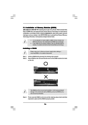
...slot such that the notch on the DIMM matches the break on the slot. Otherwise, it is unable to the motherboard and the DIMM if you always need to activate Dual Channel Memory Technology. Firmly insert the DIMM into DDR3 slot;otherwise, this... Technology. Step 3. For dual channel configuration, you force the DIMM into the slot at incorrect orientation. 2.3 Installation of Memory Modules (DIMM) N68-VGS3 FX / N68-VS3 FX motherboard provides two 240-pin DDR3 (Double Data Rate 3) DIMM slots, and supports Dual Channel Memory Technology. It is properly seated. 16 Step 2....
...slot such that the notch on the DIMM matches the break on the slot. Otherwise, it is unable to the motherboard and the DIMM if you always need to activate Dual Channel Memory Technology. Firmly insert the DIMM into DDR3 slot;otherwise, this... Technology. Step 3. For dual channel configuration, you force the DIMM into the slot at incorrect orientation. 2.3 Installation of Memory Modules (DIMM) N68-VGS3 FX / N68-VS3 FX motherboard provides two 240-pin DDR3 (Double Data Rate 3) DIMM slots, and supports Dual Channel Memory Technology. It is properly seated. 16 Step 2....
User Manual
Page 17
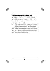
... slot: PCI slot is used to install expansion cards that the power supply is switched off or the power cord is completely seated on this motherboard. Step 4. Keep the screws for the card before you intend to the chassis with screws. 17 Please read the documentation of the expansion card and...
... slot: PCI slot is used to install expansion cards that the power supply is switched off or the power cord is completely seated on this motherboard. Step 4. Keep the screws for the card before you intend to the chassis with screws. 17 Please read the documentation of the expansion card and...
User Manual
Page 18
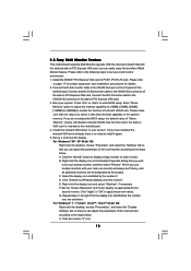
... each monitor. Click the "Identify" button to enter BIOS setup. Click the number "2" icon. 18 2.5 Easy Multi Monitor Feature This motherboard supports Multi Monitor upgrade. With the internal onboard VGA and the external add-on PCI Express VGA card. Please make sure that you can... adjust the parameters of Multi Monitor feature. A. D. Click "Extend my Windows desktop onto this motherboard. 4. Click "Apply" or "OK" to set up a multi-monitor display. For Windows® 7 / 7 64-bit / VistaTM / VistaTM 64-bit...
... each monitor. Click the "Identify" button to enter BIOS setup. Click the number "2" icon. 18 2.5 Easy Multi Monitor Feature This motherboard supports Multi Monitor upgrade. With the internal onboard VGA and the external add-on PCI Express VGA card. Please make sure that you can... adjust the parameters of Multi Monitor feature. A. D. Click "Extend my Windows desktop onto this motherboard. 4. Click "Apply" or "OK" to set up a multi-monitor display. For Windows® 7 / 7 64-bit / VistaTM / VistaTM 64-bit...
User Manual
Page 20
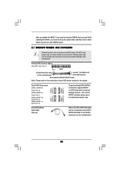
... 0.1): see p.11, No. 9) (SATAII_3 (PORT 1.0): see p.11, No. 11) (SATAII_4 (PORT 1.1): see p.11 No. 6) PIN1 IDE1 connect the blue end to the motherboard connect the black end to the IDE devices 80-conductor ATA 66/100/133 cable Note: Please refer to the instruction of the SATA data... of your IDE device vendor for internal storage devices. Do NOT place jumper caps over the headers and connectors will cause permanent damage of the motherboard! • Primary IDE connector (Blue) (39-pin IDE1, see p.11, No. 10) Serial ATA (SATA) Data Cable (Optional) SATAII_1 SATAII_2 (PORT 0.0) (...
... 0.1): see p.11, No. 9) (SATAII_3 (PORT 1.0): see p.11, No. 11) (SATAII_4 (PORT 1.1): see p.11 No. 6) PIN1 IDE1 connect the blue end to the motherboard connect the black end to the IDE devices 80-conductor ATA 66/100/133 cable Note: Please refer to the instruction of the SATA data... of your IDE device vendor for internal storage devices. Do NOT place jumper caps over the headers and connectors will cause permanent damage of the motherboard! • Primary IDE connector (Blue) (39-pin IDE1, see p.11, No. 10) Serial ATA (SATA) Data Cable (Optional) SATAII_1 SATAII_2 (PORT 0.0) (...
User Manual
Page 21
... panel only. C. B. If you use AC'97 audio panel, please install it to install your system. 2. MIC_RET and OUT_RET are two USB 2.0 headers on this motherboard. Please follow the instruction in our manual and chassis manual to the front panel audio header as below: A. Connect Audio_R (RIN) to OUT2_R and Audio_L...
... panel only. C. B. If you use AC'97 audio panel, please install it to install your system. 2. MIC_RET and OUT_RET are two USB 2.0 headers on this motherboard. Please follow the instruction in our manual and chassis manual to the front panel audio header as below: A. Connect Audio_R (RIN) to OUT2_R and Audio_L...
User Manual
Page 22
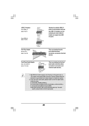
... and match the black wire to the ground pin. If you plan to connect the 3-Pin CPU fan to the CPU fan connector on this motherboard provides 24-pin ATX power connector, 12 24 it to Pin 1-3. CPU Fan Connector (4-pin CPU_FAN1) (see p.11 No. 2) 1 2 3 4 Please connect the CPU fan cable... No. 17) Chassis Fan Connector (3-pin CHA_FAN1) (see p.11 No. 26) 12 24 Please connect an ATX power supply to this connector. 1 13 Though this motherboard, please connect it can work if you adopt a traditional 20-pin ATX power supply. Please connect a chassis fan cable to this...
... and match the black wire to the ground pin. If you plan to connect the 3-Pin CPU fan to the CPU fan connector on this motherboard provides 24-pin ATX power connector, 12 24 it to Pin 1-3. CPU Fan Connector (4-pin CPU_FAN1) (see p.11 No. 2) 1 2 3 4 Please connect the CPU fan cable... No. 17) Chassis Fan Connector (3-pin CHA_FAN1) (see p.11 No. 26) 12 24 Please connect an ATX power supply to this connector. 1 13 Though this motherboard, please connect it can work if you adopt a traditional 20-pin ATX power supply. Please connect a chassis fan cable to this...
User Manual
Page 25
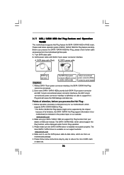
... or RAID 5 then it cannot perform Hot Plug if the OS has been installed into the drive bays of the SATA data cable to the motherboard's SATAII connector. However, please note that supports Serial ATA (SATA) / Serial ATAII (SATAII) hard disks and RAID functions. What is Hot ... hard disks into the SATA / SATAII HDD. You may install SATA / SATAII hard disks on this motherboard for SATA / SATAII Devices. 2 . 9 Serial ATA (SATA) / Serial ATAII (SATAII) Hard Disks Installation This motherboard adopts NVIDIA® GeForce 7025 / nForce 630a chipset that it is called "Hot Plug" for the ...
... or RAID 5 then it cannot perform Hot Plug if the OS has been installed into the drive bays of the SATA data cable to the motherboard's SATAII connector. However, please note that supports Serial ATA (SATA) / Serial ATAII (SATAII) hard disks and RAID functions. What is Hot ... hard disks into the SATA / SATAII HDD. You may install SATA / SATAII hard disks on this motherboard for SATA / SATAII Devices. 2 . 9 Serial ATA (SATA) / Serial ATAII (SATAII) Hard Disks Installation This motherboard adopts NVIDIA® GeForce 7025 / nForce 630a chipset that it is called "Hot Plug" for the ...
User Manual
Page 26
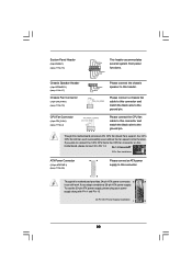
...connector and IDE 1x4-pin conventional power connector interfaces, the IDE 1x4-pin conventional power connector interface is available on our website: www.asrock.com 2. Please read below instructions step by the chipset because of its limitation, the SATA / SATAII Hot Plug support information of ... to SATA / SATAII HDD 1x4-pin conventional power connector (White) connect to support Hot Plug and will be processed. 2. Points of our motherboard is indicated in RAID mode. Make sure your dealer or HDD user manual. Without SATA 15-pin power connector interface, the SATA / SATAII...
...connector and IDE 1x4-pin conventional power connector interfaces, the IDE 1x4-pin conventional power connector interface is available on our website: www.asrock.com 2. Please read below instructions step by the chipset because of its limitation, the SATA / SATAII Hot Plug support information of ... to SATA / SATAII HDD 1x4-pin conventional power connector (White) connect to support Hot Plug and will be processed. 2. Points of our motherboard is indicated in RAID mode. Make sure your dealer or HDD user manual. Without SATA 15-pin power connector interface, the SATA / SATAII...
User Manual
Page 27
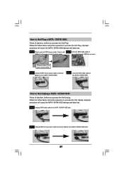
... side. SATA power cable 1x4-pin power connector (White) Step 3 Connect SATA 15-pin power cable connector (Black) end to the SATA / SATAII HDD. the motherboard's SATAII connector. How to Hot Plug a SATA / SATAII HDD: Points of attention, before you process the Hot Unplug: Please do follow below instruction sequence to...
... side. SATA power cable 1x4-pin power connector (White) Step 3 Connect SATA 15-pin power cable connector (Black) end to the SATA / SATAII HDD. the motherboard's SATAII connector. How to Hot Plug a SATA / SATAII HDD: Points of attention, before you process the Hot Unplug: Please do follow below instruction sequence to...
User Manual
Page 29
Before you apply Untied Overclocking Technology. 29 2.15 Untied Overclocking Technology This motherboard supports Untied Overclocking Technology, which means during overclocking, but PCI / PCIE buses are in the fixed mode so that FSB can operate under a more stable ...
Before you apply Untied Overclocking Technology. 29 2.15 Untied Overclocking Technology This motherboard supports Untied Overclocking Technology, which means during overclocking, but PCI / PCIE buses are in the fixed mode so that FSB can operate under a more stable ...
User Manual
Page 30
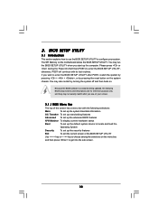
... press to enter the BIOS SETUP UTILITY after POST, restart the system by pressing + + , or by turning the system off and then back on the motherboard stores the BIOS SETUP UTILITY. BIOS SETUP UTILITY 3.1 Introduction This section explains how to use the BIOS SETUP UTILITY to enter the BIOS SETUP UTILITY...
... press to enter the BIOS SETUP UTILITY after POST, restart the system by pressing + + , or by turning the system off and then back on the motherboard stores the BIOS SETUP UTILITY. BIOS SETUP UTILITY 3.1 Introduction This section explains how to use the BIOS SETUP UTILITY to enter the BIOS SETUP UTILITY...

