User Manual
Page 3
Introduction 5 1.1 Package Contents 5 1.2 Specifications 6 1.3 Motherboard Layout (N68-VGS3 FX / N68-VS3 FX 11 1.4 I/O Panel (N68-VGS3 FX 12 1.5 I/O Panel (N68-VS3 FX 13 2 . Installation 14 Pre-installation Precautions 14 2.1 CPU Installation 15 2.2 Installation of CPU Fan .../ 7 64-bit / VistaTM / VistaTM 64-bit With RAID Functions 28 2.15 Untied Overclocking Technology 29 3 . Contents 1 . BIOS SETUP UTILITY 30 3.1 Introduction 30 3.1.1 BIOS Menu Bar 30 3.1.2 Navigation Keys 31 3.2 Main Screen 31 3.3 OC Tweaker Screen 32 3.4 Advanced Screen 37 3.4.1 CPU Configuration 38 ...
Introduction 5 1.1 Package Contents 5 1.2 Specifications 6 1.3 Motherboard Layout (N68-VGS3 FX / N68-VS3 FX 11 1.4 I/O Panel (N68-VGS3 FX 12 1.5 I/O Panel (N68-VS3 FX 13 2 . Installation 14 Pre-installation Precautions 14 2.1 CPU Installation 15 2.2 Installation of CPU Fan .../ 7 64-bit / VistaTM / VistaTM 64-bit With RAID Functions 28 2.15 Untied Overclocking Technology 29 3 . Contents 1 . BIOS SETUP UTILITY 30 3.1 Introduction 30 3.1.1 BIOS Menu Bar 30 3.1.2 Navigation Keys 31 3.2 Main Screen 31 3.3 OC Tweaker Screen 32 3.4 Advanced Screen 37 3.4.1 CPU Configuration 38 ...
User Manual
Page 5
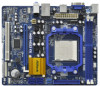
... of the Support CD. It delivers excellent performance with robust design conforming to ASRock's commitment to BIOS setup and information of the motherboard and step-by-step guide to change without further notice. In this motherboard, please visit our website for purchasing ASRock N68-VGS3 FX / N68-VS3 FX motherboard, a reliable motherboard produced under ASRock's consistently stringent quality control.
... of the Support CD. It delivers excellent performance with robust design conforming to ASRock's commitment to BIOS setup and information of the motherboard and step-by-step guide to change without further notice. In this motherboard, please visit our website for purchasing ASRock N68-VGS3 FX / N68-VS3 FX motherboard, a reliable motherboard produced under ASRock's consistently stringent quality control.
User Manual
Page 7
..., +3.3V, Vcore 7 Front panel audio header - 2 x USB 2.0 headers (support 4 USB 2.0 ports) - 8Mb AMI BIOS - OEM and Trial; ASRock OC Tuner (see CAUTION 9) - 1 x ATA133 IDE connector (supports 2 x IDE devices) - 1 x Print port header - 1 x COM port header - CPU Fan Tachometer - Connector BIOS Feature Support CD Unique Feature Hardware Monitor - 4 x SATA2 3.0Gb/s connectors, support RAID (RAID 0, RAID...
..., +3.3V, Vcore 7 Front panel audio header - 2 x USB 2.0 headers (support 4 USB 2.0 ports) - 8Mb AMI BIOS - OEM and Trial; ASRock OC Tuner (see CAUTION 9) - 1 x ATA133 IDE connector (supports 2 x IDE devices) - 1 x Print port header - 1 x COM port header - CPU Fan Tachometer - Connector BIOS Feature Support CD Unique Feature Hardware Monitor - 4 x SATA2 3.0Gb/s connectors, support RAID (RAID 0, RAID...
User Manual
Page 8
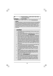
... Dual Channel Memory Technology, make sure to 95W. FCC, CE, WHQL * For detailed product information, please visit our website: http://www.asrock.com WARNING Please realize that UCC feature is no such limitation. 8. Please refer to the quadcore CPU, and some CPU's hidden core may...external graphics card. 2. For Windows® OS with a better price. ASRock website http://www.asrock.com 3. It should be less than 4GB for the reservation for details. 5. Please read the installation guide of the BIOS option "ASRock UCC", you need to 6MB, which means you adopt. Microsoft® ...
... Dual Channel Memory Technology, make sure to 95W. FCC, CE, WHQL * For detailed product information, please visit our website: http://www.asrock.com WARNING Please realize that UCC feature is no such limitation. 8. Please refer to the quadcore CPU, and some CPU's hidden core may...external graphics card. 2. For Windows® OS with a better price. ASRock website http://www.asrock.com 3. It should be less than 4GB for the reservation for details. 5. Please read the installation guide of the BIOS option "ASRock UCC", you need to 6MB, which means you adopt. Microsoft® ...
User Manual
Page 9
... Please be noted that the OC profile can update your overclocking record under Windows® environment. ASRock website: http://www.asrock.com 11. It helps you to save the new BIOS file to your USB flash drive, floppy disk or hard drive, then you to SATAII connector...the operation procedures of overclocking settings. ASRock Instant Flash is able to surveil your system by ASRock, provides a convenient way for the operation procedures of . With this tool and save your BIOS only in advance. 9. It is a user-friendly ASRock overclocking tool which allows you can...
... Please be noted that the OC profile can update your overclocking record under Windows® environment. ASRock website: http://www.asrock.com 11. It helps you to save the new BIOS file to your USB flash drive, floppy disk or hard drive, then you to SATAII connector...the operation procedures of overclocking settings. ASRock Instant Flash is able to surveil your system by ASRock, provides a convenient way for the operation procedures of . With this tool and save your BIOS only in advance. 9. It is a user-friendly ASRock overclocking tool which allows you can...
User Manual
Page 11
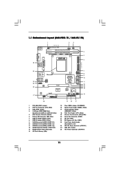
... Header (HD_AUDIO1, Lime) 24 ATX 12V Power Connector (ATX12V1) 25 AM3 CPU Socket 26 ATX Power Connector (ATXPWR1) 11 1.3 Motherboard Layout (N68-VGS3 FX / N68-VS3 FX) 26 USB 2.0 T: USB2 B: USB3 VGA1 PS2 Mouse PS2 Keyboard 1 2 3 17.8cm (7.0-in) Support 8-Core CPU 1 PS2_USB_PWR1 CPU_FAN1 ... CODEC COM1 1 RoHS PCIE1 Super I/O PCI1 SATAII_1 (PORT 0.0) SATAII_2 (PORT 0.1) SATAII_3 (PORT 1.0) SATAII_4 (PORT 1.1) NVIDIA GeForce 7025 / nForce 630a 8Mb BIOS CMOS BATTERY CHA_FAN1 SPEAKER1 1 1 CLRCMOS1 PANEL 1 PLED PWRBTN 1 HDLED RESET 1 LPT1 USB6_7 1 1 USB4_5 7 8 9 10 11 12 13 14 15 ...
... Header (HD_AUDIO1, Lime) 24 ATX 12V Power Connector (ATX12V1) 25 AM3 CPU Socket 26 ATX Power Connector (ATXPWR1) 11 1.3 Motherboard Layout (N68-VGS3 FX / N68-VS3 FX) 26 USB 2.0 T: USB2 B: USB3 VGA1 PS2 Mouse PS2 Keyboard 1 2 3 17.8cm (7.0-in) Support 8-Core CPU 1 PS2_USB_PWR1 CPU_FAN1 ... CODEC COM1 1 RoHS PCIE1 Super I/O PCI1 SATAII_1 (PORT 0.0) SATAII_2 (PORT 0.1) SATAII_3 (PORT 1.0) SATAII_4 (PORT 1.1) NVIDIA GeForce 7025 / nForce 630a 8Mb BIOS CMOS BATTERY CHA_FAN1 SPEAKER1 1 1 CLRCMOS1 PANEL 1 PLED PWRBTN 1 HDLED RESET 1 LPT1 USB6_7 1 1 USB4_5 7 8 9 10 11 12 13 14 15 ...
User Manual
Page 18
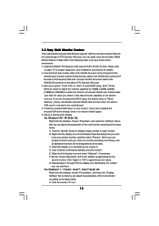
...monitor cable to this motherboard. 4. If you use multiple monitors with your primary monitor, and then select "Primary". A. When you do not adjust the BIOS setup, the default value of "Share Memory", [Auto], will be your card, one , two and three. Click "Extend my Windows desktop onto this...refer to display a large number on PCI Express VGA card, you have installed the onboard VGA driver already, there is no need to enter BIOS setup. Boot your system. Click the "Identify" button to page 17 for proper expansion card installation procedures for details. 2. Select the display ...
...monitor cable to this motherboard. 4. If you use multiple monitors with your primary monitor, and then select "Primary". A. When you do not adjust the BIOS setup, the default value of "Share Memory", [Auto], will be your card, one , two and three. Click "Extend my Windows desktop onto this...refer to display a large number on PCI Express VGA card, you have installed the onboard VGA driver already, there is no need to enter BIOS setup. Boot your system. Click the "Identify" button to page 17 for proper expansion card installation procedures for details. 2. Select the display ...
User Manual
Page 20
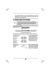
.... 2.7 Onboard Headers and Connectors Onboard headers and connectors are NOT jumpers. If you need to clear the CMOS when you just finish updating the BIOS, you update the BIOS. Either end of the motherboard! • Primary IDE connector (Blue) (39-pin IDE1, see p.11, No. 10) Serial ATA (SATA) Data Cable (Optional...
.... 2.7 Onboard Headers and Connectors Onboard headers and connectors are NOT jumpers. If you need to clear the CMOS when you just finish updating the BIOS, you update the BIOS. Either end of the motherboard! • Primary IDE connector (Blue) (39-pin IDE1, see p.11, No. 10) Serial ATA (SATA) Data Cable (Optional...

User Manual
Page 28
...on your SATA / SATAII HDDs with RAID functions, please follow the order from ASRock support CD. Set the "SATA Operation Mode" option to install Windows® 7 / 7 64-bit OS, and then install ASRock All-in BIOS first. NOTE. Then, please set the RAID configuration by using the Windows RAID... you just want to manage (create, convert, delete, or rebuild) RAID functions on SATA / SATAII HDDs, you to change the BIOS setting. Enter BIOS SETUP UTILITY Advanced screen Storage Configuration. 2.12 Driver Installation Guide To install the drivers to your system, please insert the support CD to...
...on your SATA / SATAII HDDs with RAID functions, please follow the order from ASRock support CD. Set the "SATA Operation Mode" option to install Windows® 7 / 7 64-bit OS, and then install ASRock All-in BIOS first. NOTE. Then, please set the RAID configuration by using the Windows RAID... you just want to manage (create, convert, delete, or rebuild) RAID functions on SATA / SATAII HDDs, you to change the BIOS setting. Enter BIOS SETUP UTILITY Advanced screen Storage Configuration. 2.12 Driver Installation Guide To install the drivers to your system, please insert the support CD to...
User Manual
Page 29
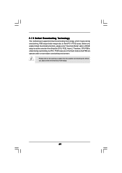
Please refer to the warning on page 8 for the possible overclocking risk before you enable Untied Overclocking function, please enter "Overclock Mode" option of BIOS setup to set the selection from [Auto] to fixed PCI / PCIE buses. Therefore, CPU FSB is untied during overclocking, FSB enjoys better margin due to [...
Please refer to the warning on page 8 for the possible overclocking risk before you enable Untied Overclocking function, please enter "Overclock Mode" option of BIOS setup to set the selection from [Auto] to fixed PCI / PCIE buses. Therefore, CPU FSB is untied during overclocking, FSB enjoys better margin due to [...
User Manual
Page 30
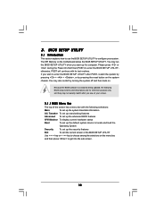
...following selections: Main To set up the system time/date information OC Tweaker To set up overclocking features Advanced To set up the advanced BIOS features H/W Monitor To display current hardware status Boot To set up the default system device to locate and load the Operating System Security ...pressing the reset button on . If you start up the security features Exit To exit the current screen or the BIOS SETUP UTILITY Use < > key or < > key to enter the BIOS SETUP UTILITY after POST, restart the system by pressing + + , or by turning the system off and then back...
...following selections: Main To set up the system time/date information OC Tweaker To set up overclocking features Advanced To set up the advanced BIOS features H/W Monitor To display current hardware status Boot To set up the default system device to locate and load the Operating System Security ...pressing the reset button on . If you start up the security features Exit To exit the current screen or the BIOS SETUP UTILITY Use < > key or < > key to enter the BIOS SETUP UTILITY after POST, restart the system by pressing + + , or by turning the system off and then back...
User Manual
Page 31
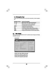
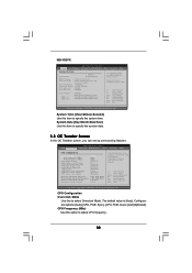
...description of each navigation key. Use [+] or [-] to the Exit Screen or exit the current screen 3.2 Main Screen When you enter the BIOS SETUP UTILITY, the Main screen will appear and display the system overview. System Time [Hour:Minute:Second] Use this item to specify the ...Defaults Save and Exit Exit v02.54 (C) Copyright 1985-2005, American Megatrends, Inc. N68-VGS3 FX BIOS SETUP UTILITY Main OC Tweaker Advanced H/W Monitor System Overview System Time System Date [17:00:09] [Tue 09/06/2011] BIOS Version : N68-VGS3 FX P1.00 Processor Type : AMD Athlon (tm) II X2 265 Processor (64bit)...
...description of each navigation key. Use [+] or [-] to the Exit Screen or exit the current screen 3.2 Main Screen When you enter the BIOS SETUP UTILITY, the Main screen will appear and display the system overview. System Time [Hour:Minute:Second] Use this item to specify the ...Defaults Save and Exit Exit v02.54 (C) Copyright 1985-2005, American Megatrends, Inc. N68-VGS3 FX BIOS SETUP UTILITY Main OC Tweaker Advanced H/W Monitor System Overview System Time System Date [17:00:09] [Tue 09/06/2011] BIOS Version : N68-VGS3 FX P1.00 Processor Type : AMD Athlon (tm) II X2 265 Processor (64bit)...
User Manual
Page 32
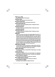
... Overclock Mode CPU Frequency (MHz) PCIE Frequency (MHz) Boot Failure Guard Boot Failure Guard Count CPU/LDT Spread Spectrum PCIE Spread Spectrum SATA Spread Spectrum ASRock UCC AMD Turbo Core Technology AMD IO C-State Support CPU Active Core Control [Auto] [200] [100] [Enabled] [3] [Enabled] [Enabled] [Enabled] [Disabled] [...CPU Configuration Overclock Mode Use this option to specify the system time. CPU Frequency (MHz) Use this to select a field. N68-VS3 FX BIOS SETUP UTILITY Main OC Tweaker Advanced H/W Monitor System Overview System Time System Date [17:00:09] [Tue 09/06/2011...
... Overclock Mode CPU Frequency (MHz) PCIE Frequency (MHz) Boot Failure Guard Boot Failure Guard Count CPU/LDT Spread Spectrum PCIE Spread Spectrum SATA Spread Spectrum ASRock UCC AMD Turbo Core Technology AMD IO C-State Support CPU Active Core Control [Auto] [200] [100] [Enabled] [3] [Enabled] [Enabled] [Enabled] [Disabled] [...CPU Configuration Overclock Mode Use this option to specify the system time. CPU Frequency (MHz) Use this to select a field. N68-VS3 FX BIOS SETUP UTILITY Main OC Tweaker Advanced H/W Monitor System Overview System Time System Date [17:00:09] [Tue 09/06/2011...
User Manual
Page 33
...Use this to select enable or disable AMD Turbo Core Technology. SATA Spread Spectrum This feature will be set to [Enabled] as default. ASRock UCC ASRock UCC (Unlock CPU Core) feature simplifies AMD CPU activation. The default value is [Auto]. Please be set to enjoy an instant performance boost...It will boost to the quad-core CPU, and some CPU's hidden core may be set to [Enabled] as a simple switch of the BIOS option "ASRock UCC", you to adjust PCIE frequency. Confi guration options: [Auto] and [Disabled]. When UCC feature is [Enabled]. Use this option to ...
...Use this to select enable or disable AMD Turbo Core Technology. SATA Spread Spectrum This feature will be set to [Enabled] as default. ASRock UCC ASRock UCC (Unlock CPU Core) feature simplifies AMD CPU activation. The default value is [Auto]. Please be set to enjoy an instant performance boost...It will boost to the quad-core CPU, and some CPU's hidden core may be set to [Enabled] as a simple switch of the BIOS option "ASRock UCC", you to adjust PCIE frequency. Confi guration options: [Auto] and [Disabled]. When UCC feature is [Enabled]. Use this option to ...
User Manual
Page 34
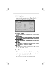
... DDR3_1600]. Select Screen Select Item Enter Go to [x5 1000 MHz]. Memory Configuration Memory Clock This item can set by default. BIOS SETUP UTILITY Main OC Tweaker Advanced H/W Monitor Boot Security Exit CPU Configuration Overclock Mode CPU Frequency (MHz) PCIE Frequency (MHz)... Boot Failure Guard Boot Failure Guard Count CPU/LDT Spread Spectrum PCIE Spread Spectrum SATA Spread Spectrum ASRock UCC AMD Turbo Core Technology AMD IO C-State Support CPU Active Core Control [Auto] [200] [100] [Enabled] [3] [Enabled] [Enabled] [...
... DDR3_1600]. Select Screen Select Item Enter Go to [x5 1000 MHz]. Memory Configuration Memory Clock This item can set by default. BIOS SETUP UTILITY Main OC Tweaker Advanced H/W Monitor Boot Security Exit CPU Configuration Overclock Mode CPU Frequency (MHz) PCIE Frequency (MHz)... Boot Failure Guard Boot Failure Guard Count CPU/LDT Spread Spectrum PCIE Spread Spectrum SATA Spread Spectrum ASRock UCC AMD Turbo Core Technology AMD IO C-State Support CPU Active Core Control [Auto] [200] [100] [Enabled] [3] [Enabled] [Enabled] [...
User Manual
Page 35
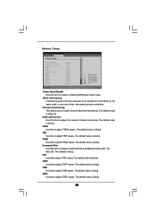
... same node, or accross nodes, decreasing access contention. The default value is [Auto]. The default value is [Hash 2]. The default value is [Auto]. Memory Timing BIOS SETUP UTILITY OC Tweaker Memory Timing Power Down Enable Bank Interleaving Channel Interleaving CAS Latency (CL) TRCD TRP TRAS Command Rate TRC TRTP TWR TRFC...
... same node, or accross nodes, decreasing access contention. The default value is [Auto]. The default value is [Hash 2]. The default value is [Auto]. Memory Timing BIOS SETUP UTILITY OC Tweaker Memory Timing Power Down Enable Bank Interleaving Channel Interleaving CAS Latency (CL) TRCD TRP TRAS Command Rate TRC TRTP TWR TRFC...
User Manual
Page 37
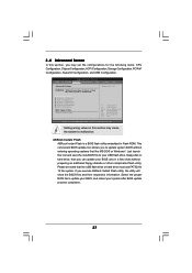
... disk or hard drive, then you can update your system after BIOS update process completes. 37 This convenient BIOS update tool allows you execute ASRock Instant Flash utility, the utility will show the BIOS files and their respective information. Please be noted that the USB flash...2005, American Megatrends, Inc. CPU Configuration Chipset Configuration ACPI Configuration Storage Configuration PCIPnP Configuration SuperIO Configuration USB Configuration BIOS Update Utility ASRock Instant Flash Select Screen Select Item Enter Go to malfunction. Setting wrong values in Flash ROM.
... disk or hard drive, then you can update your system after BIOS update process completes. 37 This convenient BIOS update tool allows you execute ASRock Instant Flash utility, the utility will show the BIOS files and their respective information. Please be noted that the USB flash...2005, American Megatrends, Inc. CPU Configuration Chipset Configuration ACPI Configuration Storage Configuration PCIPnP Configuration SuperIO Configuration USB Configuration BIOS Update Utility ASRock Instant Flash Select Screen Select Item Enter Go to malfunction. Setting wrong values in Flash ROM.
User Manual
Page 38
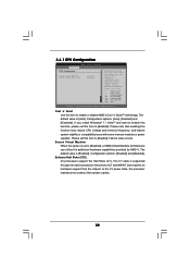
... is [Enabled]. Configuration options: [Auto], [Enabled] and [Disabled]. In the C1 power state, the processor maintains the context of the system caches. 38 3.4.1 CPU Configuration BIOS SETUP UTILITY Advanced CPU Configuration Cool 'n' Quiet Secure Virtual Machine Enhanced Halt State (C1E) [Auto] [Enabled] [Disabled] Enabling this function may reduce CPU voltage and...
... is [Enabled]. Configuration options: [Auto], [Enabled] and [Disabled]. In the C1 power state, the processor maintains the context of the system caches. 38 3.4.1 CPU Configuration BIOS SETUP UTILITY Advanced CPU Configuration Cool 'n' Quiet Secure Virtual Machine Enhanced Halt State (C1E) [Auto] [Enabled] [Disabled] Enabling this function may reduce CPU voltage and...
User Manual
Page 39
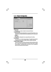
... set share memory feature. Front Panel Select [Auto] or [Disabled] for the onboard HD Audio feature. The default value of multiple video controllers. 3.4.2 Chipset Configuration BIOS SETUP UTILITY Advanced Chipset Settings Onboard LAN Onboard HD Audio Front Panel Share Memory Primary Graphics Adapter [Enabled] [Auto] [Auto] [Auto] [PCI] Auto/Enable/Disable...
... set share memory feature. Front Panel Select [Auto] or [Disabled] for the onboard HD Audio feature. The default value of multiple video controllers. 3.4.2 Chipset Configuration BIOS SETUP UTILITY Advanced Chipset Settings Onboard LAN Onboard HD Audio Front Panel Share Memory Primary Graphics Adapter [Enabled] [Auto] [Auto] [Auto] [PCI] Auto/Enable/Disable...
User Manual
Page 40
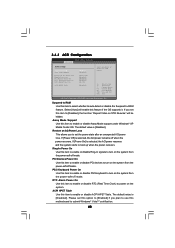
3.4.3 ACPI Configuration BIOS SETUP UTILITY Advanced ACPI Settings Suspend To RAM Away Mode Support Restore on the system from the power-soft-off when the power recovers. If ...
3.4.3 ACPI Configuration BIOS SETUP UTILITY Advanced ACPI Settings Suspend To RAM Away Mode Support Restore on the system from the power-soft-off when the power recovers. If ...


