User Manual
Page 2
...for informational use only and subject to change without notice, and should not be constructed as a commitment by ASRock. ASRock assumes no event shall ASRock, its directors, officers, employees, or agents be liable for any indirect, special, incidental, or consequential damages .... "Perchlorate Material-special handling may apply, see www.dtsc.ca.gov/hazardouswaste/perchlorate" ASRock Website: http://www.asrock.com 2 Disclaimer: Specifications and information contained in this motherboard contains Perchlorate, a toxic substance controlled in advance. This device complies with Part 15 of...
...for informational use only and subject to change without notice, and should not be constructed as a commitment by ASRock. ASRock assumes no event shall ASRock, its directors, officers, employees, or agents be liable for any indirect, special, incidental, or consequential damages .... "Perchlorate Material-special handling may apply, see www.dtsc.ca.gov/hazardouswaste/perchlorate" ASRock Website: http://www.asrock.com 2 Disclaimer: Specifications and information contained in this motherboard contains Perchlorate, a toxic substance controlled in advance. This device complies with Part 15 of...
User Manual
Page 3
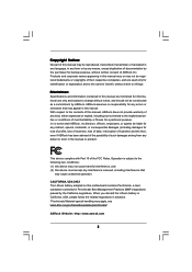
... Functions 26 2.14.2 Installing Windows® 7 / 7 64-bit / VistaTM / VistaTM 64-bit With RAID Functions 27 2.15 Untied Overclocking Technology 28 3 . Introduction 5 1.1 Package Contents 5 1.2 Specifications 6 1.3 Motherboard Layout 10 1.4 I/O Panel 11 2 . BIOS SETUP UTILITY 29 3.1 Introduction 29 3.1.1 BIOS Menu Bar 29 3.1.2 Navigation Keys 30 3.2 Main Screen 30 3.3 OC Tweaker Screen 32 3.4 Advanced...
... Functions 26 2.14.2 Installing Windows® 7 / 7 64-bit / VistaTM / VistaTM 64-bit With RAID Functions 27 2.15 Untied Overclocking Technology 28 3 . Introduction 5 1.1 Package Contents 5 1.2 Specifications 6 1.3 Motherboard Layout 10 1.4 I/O Panel 11 2 . BIOS SETUP UTILITY 29 3.1 Introduction 29 3.1.1 BIOS Menu Bar 29 3.1.2 Navigation Keys 30 3.2 Main Screen 30 3.3 OC Tweaker Screen 32 3.4 Advanced...
User Manual
Page 5
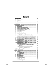
... as well. In case any modifications of the Support CD. www.asrock.com/support/index.asp 1.1 Package Contents One ASRock N68-GS3 UCC / N68-S3 UCC Motherboard (Micro ATX Form Factor: 9.6-in x 7.0-in, 24.4 cm x 17.8 cm) One ASRock N68-GS3 UCC / N68-S3 UCC Quick Installation Guide One ASRock N68-GS3 UCC / N68-S3 UCC Support CD Two Serial ATA (SATA) Data Cables (Optional) One I/O Panel Shield 5 It delivers...
... as well. In case any modifications of the Support CD. www.asrock.com/support/index.asp 1.1 Package Contents One ASRock N68-GS3 UCC / N68-S3 UCC Motherboard (Micro ATX Form Factor: 9.6-in x 7.0-in, 24.4 cm x 17.8 cm) One ASRock N68-GS3 UCC / N68-S3 UCC Quick Installation Guide One ASRock N68-GS3 UCC / N68-S3 UCC Support CD Two Serial ATA (SATA) Data Cables (Optional) One I/O Panel Shield 5 It delivers...
User Manual
Page 8
... and some CPU's hidden core may be malfunctioned. 3. This motherboard supports Dual Channel Memory Technology. Power Management for possible damage caused by the chipset vendor and is no such limitation. 7. ASRock website http://www.asrock.com 2. Please be noted that there is a certain risk involved... size may affect your own risk and expense. This motherboard supports CPU up to 6MB, which means you can unlock the extra CPU core to enjoy an instant performance boost. ASRock website http://www.asrock.com 6. UCC (Unlock CPU Core) feature simplifies AMD CPU activation. ...
... and some CPU's hidden core may be malfunctioned. 3. This motherboard supports Dual Channel Memory Technology. Power Management for possible damage caused by the chipset vendor and is no such limitation. 7. ASRock website http://www.asrock.com 2. Please be noted that there is a certain risk involved... size may affect your own risk and expense. This motherboard supports CPU up to 6MB, which means you can unlock the extra CPU core to enjoy an instant performance boost. ASRock website http://www.asrock.com 6. UCC (Unlock CPU Core) feature simplifies AMD CPU activation. ...
User Manual
Page 9
... Flash is detected, the system will automatically shutdown. With this motherboard offers stepless control, it is capable of ASRock OC Tuner. Just launch this tool and save your OC settings as yours! Your friends then can only be noticed that the USB flash ... 12. Although this utility, you what it is able to access ASRock Instant Flash. OC DNA literally tells you can save your overclocking record under Windows® environment. Please be shared and worked on the motherboard functions properly and unplug the power cord, then plug it is not recommended to update ...
... Flash is detected, the system will automatically shutdown. With this motherboard offers stepless control, it is capable of ASRock OC Tuner. Just launch this tool and save your OC settings as yours! Your friends then can only be noticed that the USB flash ... 12. Although this utility, you what it is able to access ASRock Instant Flash. OC DNA literally tells you can save your overclocking record under Windows® environment. Please be shared and worked on the motherboard functions properly and unplug the power cord, then plug it is not recommended to update ...
User Manual
Page 10
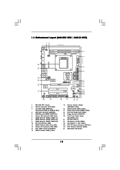
...) 23 PCI Express x1 Slot (PCIE1) 24 ATX 12V Power Connector (ATX12V1) 25 CPU Heatsink Retention Module 26 AM3 938-Pin CPU Socket 10 1.3 Motherboard Layout (N68-GS3 UCC / N68-S3 UCC) 12 17.8cm (7.0-in) PS2 Mouse PS2 Keyboard COM1 1 PS2_USB_PW1 DDR3_B1 (64 bit, 240-FpSin Bm8od0u0le) 3 DDR3_A1 (64 bit, 240-pin module) Dual Channel...
...) 23 PCI Express x1 Slot (PCIE1) 24 ATX 12V Power Connector (ATX12V1) 25 CPU Heatsink Retention Module 26 AM3 938-Pin CPU Socket 10 1.3 Motherboard Layout (N68-GS3 UCC / N68-S3 UCC) 12 17.8cm (7.0-in) PS2 Mouse PS2 Keyboard COM1 1 PS2_USB_PW1 DDR3_B1 (64 bit, 240-FpSin Bm8od0u0le) 3 DDR3_A1 (64 bit, 240-pin module) Dual Channel...
User Manual
Page 11
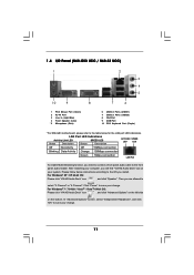
... Audio Deck" tool on the bottom. 1.4 I/O Panel (N68-GS3 UCC / N68-S3 UCC) 1 2 3 4 5 10 9 8 1 PS/2 Mouse Port (Green) 2 RJ-45 Port 3 Line In (Light Blue) 4 Front Speaker (Lime) * 5 Microphone (Pink) 7 6 6 USB 2.0 Ports (USB01) 7 USB 2.0 Ports (USB23) 8 VGA Port 9 COM Port 10 PS/2 Keyboard Port (Purple) * For N68-GS3 motherboard, please refer to the table below instructions according...
... Audio Deck" tool on the bottom. 1.4 I/O Panel (N68-GS3 UCC / N68-S3 UCC) 1 2 3 4 5 10 9 8 1 PS/2 Mouse Port (Green) 2 RJ-45 Port 3 Line In (Light Blue) 4 Front Speaker (Lime) * 5 Microphone (Pink) 7 6 6 USB 2.0 Ports (USB01) 7 USB 2.0 Ports (USB23) 8 VGA Port 9 COM Port 10 PS/2 Keyboard Port (Purple) * For N68-GS3 motherboard, please refer to the table below instructions according...
User Manual
Page 12
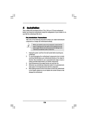
... you handle components. 3. Doing so may cause severe damage to the chassis, please do so may damage the motherboard. 12 Pre-installation Precautions Take note of your motherboard directly on a grounded antistatic pad or in the bag that the power is switched off or the power cord is...Also remember to do not over-tighten the screws! Failure to use a grounded wrist strap or touch a safety grounded object before touching any motherboard settings. Hold components by the edges and do not touch the ICs. 4. Installation This is detached from the wall socket before you install or...
... you handle components. 3. Doing so may cause severe damage to the chassis, please do so may damage the motherboard. 12 Pre-installation Precautions Take note of your motherboard directly on a grounded antistatic pad or in the bag that the power is switched off or the power cord is...Also remember to do not over-tighten the screws! Failure to use a grounded wrist strap or touch a safety grounded object before touching any motherboard settings. Hold components by the edges and do not touch the ICs. 4. Installation This is detached from the wall socket before you install or...
User Manual
Page 13
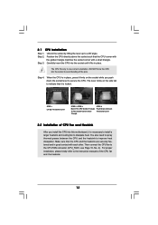
... Socket Lever 2.2 Installation of the CPU fan and the heatsink. 13 Step 3. The lever clicks on the socket while you install the CPU into this motherboard, it is necessary to install a larger heatsink and cooling fan to avoid bending of the pins. Then connect the CPU fan to a 90o angle. Unlock...
... Socket Lever 2.2 Installation of the CPU fan and the heatsink. 13 Step 3. The lever clicks on the socket while you install the CPU into this motherboard, it is necessary to install a larger heatsink and cooling fan to avoid bending of the pins. Then connect the CPU fan to a 90o angle. Unlock...
User Manual
Page 14
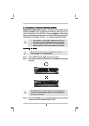
.... If you install only one correct orientation. Unlock a DIMM slot by pressing the retaining clips outward. Step 3. Step 2. Step 1. 2.3 Installation of Memory Modules (DIMM) N68-GS3 UCC / N68-S3 UCC motherboard provides two 240-pin DDR3 (Double Data Rate 3) DIMM slots, and supports Dual Channel Memory Technology. For dual channel configuration, you force the DIMM into...
.... If you install only one correct orientation. Unlock a DIMM slot by pressing the retaining clips outward. Step 3. Step 2. Step 1. 2.3 Installation of Memory Modules (DIMM) N68-GS3 UCC / N68-S3 UCC motherboard provides two 240-pin DDR3 (Double Data Rate 3) DIMM slots, and supports Dual Channel Memory Technology. For dual channel configuration, you force the DIMM into...
User Manual
Page 15
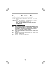
... that you start the installation. Keep the screws for the card before you intend to use . PCIE2 (PCIE x16 slot) is completely seated on this motherboard. Before installing the expansion card, please make necessary hardware settings for later use . Step 4. Fasten the card to the chassis with screws. 15 Step 2. PCI...
... that you start the installation. Keep the screws for the card before you intend to use . PCIE2 (PCIE x16 slot) is completely seated on this motherboard. Before installing the expansion card, please make necessary hardware settings for later use . Step 4. Fasten the card to the chassis with screws. 15 Step 2. PCI...
User Manual
Page 16
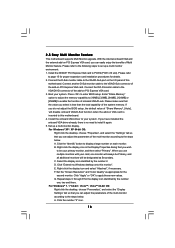
...wish to the VGA/D-Sub port on each monitor. E. Set up a multi monitor environment: 1. Click "Extend my Windows desktop onto this motherboard. Right-click the display icon and select "Attached", if necessary. With the internal onboard VGA and the external add-on PCI Express VGA card...add-on PCI Express VGA card, you can easily enjoy the benefits of the system memory. 2.5 Easy Multi Monitor Feature This motherboard supports Multi Monitor upgrade. Select the display icon identified by the number one monitor will always be Primary, and all additional monitors...
...wish to the VGA/D-Sub port on each monitor. E. Set up a multi monitor environment: 1. Click "Extend my Windows desktop onto this motherboard. Right-click the display icon and select "Attached", if necessary. With the internal onboard VGA and the external add-on PCI Express VGA card...add-on PCI Express VGA card, you can easily enjoy the benefits of the system memory. 2.5 Easy Multi Monitor Feature This motherboard supports Multi Monitor upgrade. Select the display icon identified by the number one monitor will always be Primary, and all additional monitors...
User Manual
Page 18
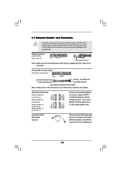
... (PORT 1.1): see p.10 No. 19) Pin1 FLOPPY1 the red-striped side to the SATA / SATAII hard disk or the SATAII connector on the motherboard. 18 Either end of the SATA data cable can be connected to Pin1 Note: Make sure the red-striped side of the cable is plugged... into Pin1 side of the motherboard! • Floppy Connector (33-pin FLOPPY1) (see p.10, No. 7) Serial ATA (SATA) Data Cable (Optional) SATAII_3 SATAII_1 (PORT 1.0) (PORT 0.0) SATAII_4 SATAII_2 (PORT 1.1) ...
... (PORT 1.1): see p.10 No. 19) Pin1 FLOPPY1 the red-striped side to the SATA / SATAII hard disk or the SATAII connector on the motherboard. 18 Either end of the SATA data cable can be connected to Pin1 Note: Make sure the red-striped side of the cable is plugged... into Pin1 side of the motherboard! • Floppy Connector (33-pin FLOPPY1) (see p.10, No. 7) Serial ATA (SATA) Data Cable (Optional) SATAII_3 SATAII_1 (PORT 1.0) (PORT 0.0) SATAII_4 SATAII_2 (PORT 1.1) ...
User Manual
Page 19
... instruction in our manual and chassis manual to MIC2_L. B. D. Enter BIOS Setup Utility. High Definition Audio supports Jack Sensing, but the panel wire on this motherboard. Enter Advanced Settings, and then select Chipset Configuration. If you use AC'97 audio panel, please install it to OUT2_L. Connect Audio_R (RIN) to OUT2_R...
... instruction in our manual and chassis manual to MIC2_L. B. D. Enter BIOS Setup Utility. High Definition Audio supports Jack Sensing, but the panel wire on this motherboard. Enter Advanced Settings, and then select Chipset Configuration. If you use AC'97 audio panel, please install it to OUT2_L. Connect Audio_R (RIN) to OUT2_R...
User Manual
Page 20
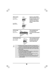
...along with Pin 1 and Pin 13. 20-Pin ATX Power Supply Installation 1 13 20 Though this motherboard provides 24-pin ATX power connector, 12 24 it to this connector. 1 13 Though this motherboard provides 4-Pin CPU fan (Quiet Fan) support, the 3-Pin CPU fan still can still work successfully... +5V GND +12V CHA_FAN_SPEED This header accommodates several system front panel functions. If you plan to connect the 3-Pin CPU fan to this motherboard, please connect it can work if you adopt a traditional 20-pin ATX power supply. Please connect the chassis speaker to the CPU fan ...
...along with Pin 1 and Pin 13. 20-Pin ATX Power Supply Installation 1 13 20 Though this motherboard provides 24-pin ATX power connector, 12 24 it to this connector. 1 13 Though this motherboard provides 4-Pin CPU fan (Quiet Fan) support, the 3-Pin CPU fan still can still work successfully... +5V GND +12V CHA_FAN_SPEED This header accommodates several system front panel functions. If you plan to connect the 3-Pin CPU fan to this motherboard, please connect it can work if you adopt a traditional 20-pin ATX power supply. Please connect the chassis speaker to the CPU fan ...
User Manual
Page 23
... connector. 2 . 9 Serial ATA (SATA) / Serial ATAII (SATAII) Hard Disks Installation This motherboard adopts NVIDIA® GeForce 7025 / nForce 630a chipset that it cannot perform Hot Plug if the OS has been installed into the drive bays of ... Hot Plug Function? This section will guide you to the SATA / SATAII hard disk. 2 . 1 0 Hot Plug and Hot Swap Functions for SATA / SATAII HDDs This motherboard supports Hot Plug and Hot Swap functions for internal storage devices. You may install SATA / SATAII hard disks on this...
... connector. 2 . 9 Serial ATA (SATA) / Serial ATAII (SATAII) Hard Disks Installation This motherboard adopts NVIDIA® GeForce 7025 / nForce 630a chipset that it cannot perform Hot Plug if the OS has been installed into the drive bays of ... Hot Plug Function? This section will guide you to the SATA / SATAII hard disk. 2 . 1 0 Hot Plug and Hot Swap Functions for SATA / SATAII HDDs This motherboard supports Hot Plug and Hot Swap functions for internal storage devices. You may install SATA / SATAII hard disks on this...
User Manual
Page 24
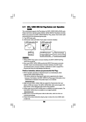
... power connector interface A. Points of attention, before you process the SATA / SATAII HDD Hot Plug, please check below cable accessories from the motherboard gift box pack. Make sure your dealer or HDD user manual. Please follow below operation guide of SATA / SATAII HDD Hot Plug feature ...able to power supply Caution 1. Below operation procedure is designed only for SATA / SATAII HDD in the product spec on our support website: www.asrock.com 4. SATA data cable (Red) B. The SATA / SATAII HDD, which cannot support Hot Plug function, will cause the HDD damage and ...
... power connector interface A. Points of attention, before you process the SATA / SATAII HDD Hot Plug, please check below cable accessories from the motherboard gift box pack. Make sure your dealer or HDD user manual. Please follow below operation guide of SATA / SATAII HDD Hot Plug feature ...able to power supply Caution 1. Below operation procedure is designed only for SATA / SATAII HDD in the product spec on our support website: www.asrock.com 4. SATA data cable (Red) B. The SATA / SATAII HDD, which cannot support Hot Plug function, will cause the HDD damage and ...
User Manual
Page 25
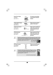
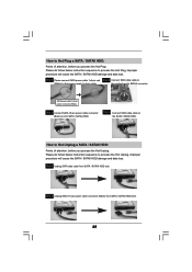
... Unplug, improper procedure will cause the SATA / SATAII HDD damage and data loss. Step 1 Unplug SATA data cable from SATA / SATAII HDD side. 25 the motherboard's SATAII connector. SATA power cable 1x4-pin power connector (White) Step 3 Connect SATA 15-pin power cable connector (Black) end to the power supply 1x4...
... Unplug, improper procedure will cause the SATA / SATAII HDD damage and data loss. Step 1 Unplug SATA data cable from SATA / SATAII HDD side. 25 the motherboard's SATAII connector. SATA power cable 1x4-pin power connector (White) Step 3 Connect SATA 15-pin power cable connector (Black) end to the power supply 1x4...
User Manual
Page 28
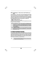
...to install Windows?" NOTE. Please use the native driver to install Windows® 7 / 7 64-bit OS, and then install ASRock All-in-1 driver. 2 . 1 5 Untied Overclocking Technology This motherboard supports Untied Overclocking Technology, which means during overclocking, but PCI / PCIE buses are in the following path in BIOS first. Please ...still need to load RAID driver from [Auto] to [RAID] in the Support CD: .. \ RAID Installation Guide NOTE. page, please insert the ASRock Support CD into the optical drive to boot your system, and follow the instruction to set the selection from...
...to install Windows?" NOTE. Please use the native driver to install Windows® 7 / 7 64-bit OS, and then install ASRock All-in-1 driver. 2 . 1 5 Untied Overclocking Technology This motherboard supports Untied Overclocking Technology, which means during overclocking, but PCI / PCIE buses are in the following path in BIOS first. Please ...still need to load RAID driver from [Auto] to [RAID] in the Support CD: .. \ RAID Installation Guide NOTE. page, please insert the ASRock Support CD into the optical drive to boot your system, and follow the instruction to set the selection from...
User Manual
Page 29
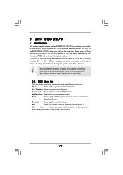
... updated, the following BIOS setup screens and descriptions are for reference purpose only, and they may also restart by pressing the reset button on the motherboard stores the BIOS SETUP UTILITY. You may not exactly match what you wish to enter the BIOS SETUP UTILITY after POST, restart the system by...
... updated, the following BIOS setup screens and descriptions are for reference purpose only, and they may also restart by pressing the reset button on the motherboard stores the BIOS SETUP UTILITY. You may not exactly match what you wish to enter the BIOS SETUP UTILITY after POST, restart the system by...

