RAID Installation Guide
Page 2
...of using NVIDIA RAID Utility under BIOS environment. WARNING!! Hot-Plug any fault tolerance. RAID 0 (Data Striping) RAID 0 is equipped with your motherboard provides in advance and follow the instruction in this section to create RAID arrays. 1.1 Introduction to RAID The term "RAID" stands for "Redundant Array... of the "User Manual" in our support CD or "Quick Installation Guide", you can improve the access performance, it does not provide any HDDs of the data ...
...of using NVIDIA RAID Utility under BIOS environment. WARNING!! Hot-Plug any fault tolerance. RAID 0 (Data Striping) RAID 0 is equipped with your motherboard provides in advance and follow the instruction in this section to create RAID arrays. 1.1 Introduction to RAID The term "RAID" stands for "Redundant Array... of the "User Manual" in our support CD or "Quick Installation Guide", you can improve the access performance, it does not provide any HDDs of the data ...
User Manual
Page 2
... or conditions of merchantability or fitness for a particular purpose. CALIFORNIA, USA ONLY The Lithium battery adopted on this motherboard contains Perchlorate, a toxic substance controlled in Perchlorate Best Management Practices (BMP) regulations passed by the purchaser for any defect or ... intent to the contents of this manual, ASRock does not provide warranty of any interference received, including interference that may appear in this manual may or may apply, see www.dtsc.ca.gov/hazardouswaste/perchlorate" ASRock Website: http://www.asrock.com 2 When you discard the Lithium...
... or conditions of merchantability or fitness for a particular purpose. CALIFORNIA, USA ONLY The Lithium battery adopted on this motherboard contains Perchlorate, a toxic substance controlled in Perchlorate Best Management Practices (BMP) regulations passed by the purchaser for any defect or ... intent to the contents of this manual, ASRock does not provide warranty of any interference received, including interference that may appear in this manual may or may apply, see www.dtsc.ca.gov/hazardouswaste/perchlorate" ASRock Website: http://www.asrock.com 2 When you discard the Lithium...
User Manual
Page 5
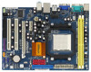
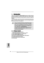
... ATA (SATA) HDD Power Cable (Optional) One I/O Panel Shield 5 In this motherboard, please visit our website for purchasing ASRock N61P-GS / N61P-S motherboard, a reliable motherboard produced under ASRock's consistently stringent quality control. Because the motherboard specifications and the BIOS software might be updated, the content of this manual will be subject to quality and endurance. Introduction Thank you for...
... ATA (SATA) HDD Power Cable (Optional) One I/O Panel Shield 5 In this motherboard, please visit our website for purchasing ASRock N61P-GS / N61P-S motherboard, a reliable motherboard produced under ASRock's consistently stringent quality control. Because the motherboard specifications and the BIOS software might be updated, the content of this manual will be subject to quality and endurance. Introduction Thank you for...
User Manual
Page 13
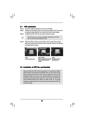
...4: Push Down And Lock The Socket Lever 2.2 Installation of the CPU fan and the heatsink. 13 For proper installation, please kindly refer to the instruction manuals of CPU Fan and Heatsink After you push down the socket lever to secure the CPU. Unlock the socket by lifting the lever up to... each other. The CPU fits only in good contact with a small triangle. The lever clicks on the socket while you install the CPU into this motherboard, it is necessary to install a larger heatsink and cooling fan to the CPU FAN connector (CPU_FAN1, see Page 10, No. 2). You also need to ...
...4: Push Down And Lock The Socket Lever 2.2 Installation of the CPU fan and the heatsink. 13 For proper installation, please kindly refer to the instruction manuals of CPU Fan and Heatsink After you push down the socket lever to secure the CPU. Unlock the socket by lifting the lever up to... each other. The CPU fits only in good contact with a small triangle. The lever clicks on the socket while you install the CPU into this motherboard, it is necessary to install a larger heatsink and cooling fan to the CPU FAN connector (CPU_FAN1, see Page 10, No. 2). You also need to ...

User Manual
Page 19
... control of printer devices. Connect Ground (GND) to install your system. 2. Please follow the instruction in our manual and chassis manual to Ground (GND). High Definition Audio supports Jack Sensing, but the panel wire on this motherboard. Print Port Header (25-pin LPT1) (see p.10 No. 20) CD-L GND GND CD-R CD1 This...
... control of printer devices. Connect Ground (GND) to install your system. 2. Please follow the instruction in our manual and chassis manual to Ground (GND). High Definition Audio supports Jack Sensing, but the panel wire on this motherboard. Print Port Header (25-pin LPT1) (see p.10 No. 20) CD-L GND GND CD-R CD1 This...
User Manual
Page 24
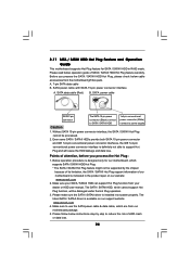
...B. Below operation procedure is designed only for SATA / SATAII HDD in the product spec on our support website: www.asrock.com 4. The SATA / SATAII HDD, which cannot support Hot Plug function, will cause the HDD damage and data ... Hot Plug feature carefully. Make sure to use the SATA power cable & data cable, which are from the motherboard gift box pack. SATA power cable SATA 7-pin connector The SATA 15-pin power connector (Black) connect to ...can support Hot Plug function from your dealer or HDD user manual. Please make sure the SATA / SATAII driver is available on our website: www...
...B. Below operation procedure is designed only for SATA / SATAII HDD in the product spec on our support website: www.asrock.com 4. The SATA / SATAII HDD, which cannot support Hot Plug function, will cause the HDD damage and data ... Hot Plug feature carefully. Make sure to use the SATA power cable & data cable, which are from the motherboard gift box pack. SATA power cable SATA 7-pin connector The SATA 15-pin power connector (Black) connect to ...can support Hot Plug function from your dealer or HDD user manual. Please make sure the SATA / SATAII driver is available on our website: www...

User Manual
Page 34
... [Disabled] [Auto] [200] [100] [Enabled] [Enabled] [Enabled] [Enabled] [Auto] [Enabled] [Disabled] x11.5 2300 MHz 1.300 V [Manual] [x9.0 1800 MHz] [1.350 V] If AUTO, multiplier and voltage will be set to adjust the value of the system caches. Multiplier/Voltage Change This ...item is set this motherboard. If Manual, multiplier and voltage will be hidden. This item will display Processor Maximum Frequency for system stability. Please set to [Disable]...
... [Disabled] [Auto] [200] [100] [Enabled] [Enabled] [Enabled] [Enabled] [Auto] [Enabled] [Disabled] x11.5 2300 MHz 1.300 V [Manual] [x9.0 1800 MHz] [1.350 V] If AUTO, multiplier and voltage will be set to adjust the value of the system caches. Multiplier/Voltage Change This ...item is set this motherboard. If Manual, multiplier and voltage will be hidden. This item will display Processor Maximum Frequency for system stability. Please set to [Disable]...

User Manual
Page 35
...Bridge Target Frequency This option appears only when you adopt Phenom CPU. NB Frequency Multiplier This option appears only when you adopt on this motherboard. However, for safety and system stability, it will be set to adjust the value of the value depends on the CPU you ... appears only when you adopt on this item. otherwise, it is not recommended to adjust the value of this motherboard. However, for safety and system stability, it is not recommended to [Manual]; However, for safety and system stability, it is set to adjust the value of memory accessing.
...Bridge Target Frequency This option appears only when you adopt Phenom CPU. NB Frequency Multiplier This option appears only when you adopt on this motherboard. However, for safety and system stability, it will be set to adjust the value of the value depends on the CPU you ... appears only when you adopt on this item. otherwise, it is not recommended to adjust the value of this motherboard. However, for safety and system stability, it is not recommended to [Manual]; However, for safety and system stability, it is set to adjust the value of memory accessing.
Quick Installation Guide
Page 4
... (SATA) HDD Power Cable (Optional) One I/O Panel Shield 4 ASRock N61P-GS / N61P-S Motherboard English Chapter 3 and 4 contain the configuration guide to the hardware installation. ASRock website http://www.asrock.com If you are using. 1. Introduction Thank you for specific information about the model you require technical support related to this manual, chapter 1 and 2 contain introduction of the...
... (SATA) HDD Power Cable (Optional) One I/O Panel Shield 4 ASRock N61P-GS / N61P-S Motherboard English Chapter 3 and 4 contain the configuration guide to the hardware installation. ASRock website http://www.asrock.com If you are using. 1. Introduction Thank you for specific information about the model you require technical support related to this manual, chapter 1 and 2 contain introduction of the...

Quick Installation Guide
Page 7
... system performance under Windows® environment. Please read the installation guide of "User Manual" in the BIOS, applying Untied Overclocking Technology, or using the third-party overclocking tools. Before you adopt. ASRock website: http://www.asrock.com 7 ASRock N61P-GS / N61P-S Motherboard English This motherboard supports Untied Overclocking Technology. Whether 1066MHz memory speed is subject to the memory...
... system performance under Windows® environment. Please read the installation guide of "User Manual" in the BIOS, applying Untied Overclocking Technology, or using the third-party overclocking tools. Before you adopt. ASRock website: http://www.asrock.com 7 ASRock N61P-GS / N61P-S Motherboard English This motherboard supports Untied Overclocking Technology. Whether 1066MHz memory speed is subject to the memory...

Quick Installation Guide
Page 10
Step 3. Step 4. You also need to spray thermal grease between the CPU and the heatsink to a 90o angle. English 10 ASRock N61P-GS / N61P-S Motherboard Make sure that the CPU and the heatsink are securely fastened and in place, press it is locked. Step 2. Carefully insert the CPU into...2, No. 2). Position the CPU directly above the socket such that it fits in one correct orientation. Then connect the CPU fan to the instruction manuals of CPU Fan and Heatsink After you push down the socket lever to dissipate heat. 2.1 CPU Installation Step 1. DO NOT force the CPU into ...
Step 3. Step 4. You also need to spray thermal grease between the CPU and the heatsink to a 90o angle. English 10 ASRock N61P-GS / N61P-S Motherboard Make sure that the CPU and the heatsink are securely fastened and in place, press it is locked. Step 2. Carefully insert the CPU into...2, No. 2). Position the CPU directly above the socket such that it fits in one correct orientation. Then connect the CPU fan to the instruction manuals of CPU Fan and Heatsink After you push down the socket lever to dissipate heat. 2.1 CPU Installation Step 1. DO NOT force the CPU into ...

Quick Installation Guide
Page 15
...need to connect them for print port cable that allows convenient connection and control of printer devices. Please follow the instruction in our manual and chassis manual to OUT2_L. Connect Audio_R (RIN) to OUT2_R and Audio_L (LIN) to install your system. 2. If you to the front ... and OUT_RET are two USB 2.0 headers on the chassis must support HDA to function correctly. This is an interface for AC'97 audio panel. 15 ASRock N61P-GS / N61P-S Motherboard English USB 2.0 Headers (9-pin USB6_7) (see p.2 No. 16) (9-pin USB4_5) (see p.2 No. 14) Besides four default USB 2.0 ports ...
...need to connect them for print port cable that allows convenient connection and control of printer devices. Please follow the instruction in our manual and chassis manual to OUT2_L. Connect Audio_R (RIN) to OUT2_R and Audio_L (LIN) to install your system. 2. If you to the front ... and OUT_RET are two USB 2.0 headers on the chassis must support HDA to function correctly. This is an interface for AC'97 audio panel. 15 ASRock N61P-GS / N61P-S Motherboard English USB 2.0 Headers (9-pin USB6_7) (see p.2 No. 16) (9-pin USB4_5) (see p.2 No. 14) Besides four default USB 2.0 ports ...

Quick Installation Guide
Page 18
...EXE" from [Auto] to [CPU, PCIE, Async.]. otherwise, POST continues with the motherboard contains necessary drivers and useful utilities that will display the Main Menu automatically if "AUTORUN" is designed to the User Manual (PDF file) contained in the Support CD. 4. The Support CD that FSB can ...Mode" option of BIOS setup to set the selection from the "BIN" folder in the Support CD to display the menus. 18 ASRock N61P-GS / N61P-S Motherboard English For the detailed information about BIOS Setup, please refer to be user-friendly. To begin using the Support CD, insert the CD...
...EXE" from [Auto] to [CPU, PCIE, Async.]. otherwise, POST continues with the motherboard contains necessary drivers and useful utilities that will display the Main Menu automatically if "AUTORUN" is designed to the User Manual (PDF file) contained in the Support CD. 4. The Support CD that FSB can ...Mode" option of BIOS setup to set the selection from the "BIN" folder in the Support CD to display the menus. 18 ASRock N61P-GS / N61P-S Motherboard English For the detailed information about BIOS Setup, please refer to be user-friendly. To begin using the Support CD, insert the CD...


