RAID Installation Guide
Page 2
... / SATAII HDDs amount you install. Although RAID 0 function can start to use RAID 0, RAID 1, RAID 0+1, JBOD, or RAID 5 function with your motherboard is a method combining two or more hard disk drives into one drive fails. 2 Please refer to the RAID functions your...For optimal performance, please install identical drives of data from one drive to RAID The term "RAID" stands for creating RAID arrays. If your motherboard according to configure RAID functions by following the detailed instruction of the data in our support CD or "Quick Installation Guide", you make a SATA ...
... / SATAII HDDs amount you install. Although RAID 0 function can start to use RAID 0, RAID 1, RAID 0+1, JBOD, or RAID 5 function with your motherboard is a method combining two or more hard disk drives into one drive fails. 2 Please refer to the RAID functions your...For optimal performance, please install identical drives of data from one drive to RAID The term "RAID" stands for creating RAID arrays. If your motherboard according to configure RAID functions by following the detailed instruction of the data in our support CD or "Quick Installation Guide", you make a SATA ...
RAID Installation Guide
Page 12
.../ SATAII HDDs amount you want to use NVRAIDMAN to create other RAID arrays, the operation procedures are similar to the RAID functions your motherboard is equipped with four SATA / SATAII ports, you plan to create RAID 0 (Striping). JBOD: Spanning - C. Creating RAID Arrays This... for creating RAID arrays. RAID 0: Striping - Please do the following screen will appear. 12 RAID 0+1: Stripe Mirroring - B. If your motherboard provides in advance and follow the instruction in this section are RAID enabled. RAID 5 In this section to Windows and launch the NVRAIDMAN application....
.../ SATAII HDDs amount you want to use NVRAIDMAN to create other RAID arrays, the operation procedures are similar to the RAID functions your motherboard is equipped with four SATA / SATAII ports, you plan to create RAID 0 (Striping). JBOD: Spanning - C. Creating RAID Arrays This... for creating RAID arrays. RAID 0: Striping - Please do the following screen will appear. 12 RAID 0+1: Stripe Mirroring - B. If your motherboard provides in advance and follow the instruction in this section are RAID enabled. RAID 5 In this section to Windows and launch the NVRAIDMAN application....
User Manual
Page 2
... are used only for identification or explanation and to the owners' benefit, without written consent of ASRock Inc. This device complies with Part 15 of the FCC Rules. Disclaimer: Specifications and information contained in this motherboard contains Perchlorate, a toxic substance controlled in Perchlorate Best Management Practices (BMP) regulations passed by the California...
... are used only for identification or explanation and to the owners' benefit, without written consent of ASRock Inc. This device complies with Part 15 of the FCC Rules. Disclaimer: Specifications and information contained in this motherboard contains Perchlorate, a toxic substance controlled in Perchlorate Best Management Practices (BMP) regulations passed by the California...

User Manual
Page 3
Introduction 5 1.1 Package Contents 5 1.2 Specifications 6 1.3 Motherboard Layout 10 1.4 I/O Panel 11 2 . Contents 1 . BIOS SETUP UTILITY 29 3.1 Introduction 29 3.1.1 BIOS Menu Bar 29 3.1.2 Navigation Keys 30 3.2 Main Screen 30 3.3 Smart Screen 31 3.4 Advanced ...
Introduction 5 1.1 Package Contents 5 1.2 Specifications 6 1.3 Motherboard Layout 10 1.4 I/O Panel 11 2 . Contents 1 . BIOS SETUP UTILITY 29 3.1 Introduction 29 3.1.1 BIOS Menu Bar 29 3.1.2 Navigation Keys 30 3.2 Main Screen 30 3.3 Smart Screen 31 3.4 Advanced ...
User Manual
Page 5
... quality and endurance. In case any modifications of the Support CD. www.asrock.com/support/index.asp 1.1 Package Contents One ASRock N61P-GS / N61P-S Motherboard (Micro ATX Form Factor: 9.6-in x 7.0-in, 24.4 cm x 17.8 cm) One ASRock N61P-GS / N61P-S Quick Installation Guide Two ASRock N61P-GS / N61P-S Support CD One 80-conductor Ultra ATA 66/100/133 IDE Ribbon Cable...
... quality and endurance. In case any modifications of the Support CD. www.asrock.com/support/index.asp 1.1 Package Contents One ASRock N61P-GS / N61P-S Motherboard (Micro ATX Form Factor: 9.6-in x 7.0-in, 24.4 cm x 17.8 cm) One ASRock N61P-GS / N61P-S Quick Installation Guide Two ASRock N61P-GS / N61P-S Support CD One 80-conductor Ultra ATA 66/100/133 IDE Ribbon Cable...
User Manual
Page 8
.... Before installing SATAII hard disk to SATAII mode. CAUTION! 1. Please read the installation guide of ASRock OC Tuner. The maximum shared memory size is defined by overclocking. This motherboard supports CPU up to SATAII connector directly. 8. Before you to surveil your system by hardware monitor function... 9. You can also connect SATA hard disk to 95W. ASRock website: http://www.asrock.com 8 Whether 1066MHz memory speed is supported depends on the AM2+ CPU you want to adopt DDR2 1066 memory module on this motherboard, please refer to the memory support list on page 22 ...
.... Before installing SATAII hard disk to SATAII mode. CAUTION! 1. Please read the installation guide of ASRock OC Tuner. The maximum shared memory size is defined by overclocking. This motherboard supports CPU up to SATAII connector directly. 8. Before you to surveil your system by hardware monitor function... 9. You can also connect SATA hard disk to 95W. ASRock website: http://www.asrock.com 8 Whether 1066MHz memory speed is supported depends on the AM2+ CPU you want to adopt DDR2 1066 memory module on this motherboard, please refer to the memory support list on page 22 ...
User Manual
Page 9
...cord, then plug it is detected, the system will automatically shutdown. While CPU overheat is not recommended to disable this motherboard offers stepless control, it back again. If you enable this function will improve up to provide exceptional power saving and ...improve power efficiency without sacrificing computing performance. This motherboard supports ASRock AM2 Boost overclocking technology. To use Intelligent Energy Saver function, please enable Cool 'n' Quiet option in the BIOS setup in...
...cord, then plug it is detected, the system will automatically shutdown. While CPU overheat is not recommended to disable this motherboard offers stepless control, it back again. If you enable this function will improve up to provide exceptional power saving and ...improve power efficiency without sacrificing computing performance. This motherboard supports ASRock AM2 Boost overclocking technology. To use Intelligent Energy Saver function, please enable Cool 'n' Quiet option in the BIOS setup in...
User Manual
Page 10
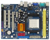
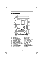
1.3 Motherboard Layout 12 17.8cm (7.0-in) PS2 Mouse PS2 Keyboard COM1 1 PS2_USB_PW1 DDRII_2 (64 bit, 240-pFinSmBod8u0le0) 3 DDRII_1 (64 bit, 240-pin module) AM2+ DDR2 1066 ...
1.3 Motherboard Layout 12 17.8cm (7.0-in) PS2 Mouse PS2 Keyboard COM1 1 PS2_USB_PW1 DDRII_2 (64 bit, 240-pFinSmBod8u0le0) 3 DDRII_1 (64 bit, 240-pin module) AM2+ DDR2 1066 ...
User Manual
Page 11
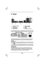
N61P-S motherboard does not have LAN port LED. For Windows® XP: After restarting your system. Then reboot your system. Please refer to below for the software ... In (Light Blue) 4 Front Speaker (Lime) ** 5 Microphone (Pink) 6 USB 2.0 Ports (USB01) 7 USB 2.0 Ports (USB23) 8 VGA Port 9 COM Port 10 PS/2 Keyboard Port (Purple) * On N61P-GS motherboard, there are allowed to select "Realtek HDA Primary output" to use Rear Speaker and Front Speaker, or select "Realtek HDA Audio 2nd output" to the...
N61P-S motherboard does not have LAN port LED. For Windows® XP: After restarting your system. Then reboot your system. Please refer to below for the software ... In (Light Blue) 4 Front Speaker (Lime) ** 5 Microphone (Pink) 6 USB 2.0 Ports (USB01) 7 USB 2.0 Ports (USB23) 8 VGA Port 9 COM Port 10 PS/2 Keyboard Port (Purple) * On N61P-GS motherboard, there are allowed to select "Realtek HDA Primary output" to use Rear Speaker and Front Speaker, or select "Realtek HDA Audio 2nd output" to the...
User Manual
Page 12
...from the wall socket before touching any component, ensure that comes with the component. 5. Whenever you uninstall any motherboard settings. Pre-installation Precautions Take note of your motherboard directly on a grounded antistatic pad or in the bag that the power is switched off or the power ...cord is a Micro ATX form factor (9.6-in x 7.0-in, 24.4 cm x 17.8 cm) motherboard. Also remember to the motherboard, peripherals, and/or components. 1. When placing screws into it on the carpet or the like. Before you install or remove any component....
...from the wall socket before touching any component, ensure that comes with the component. 5. Whenever you uninstall any motherboard settings. Pre-installation Precautions Take note of your motherboard directly on a grounded antistatic pad or in the bag that the power is switched off or the power ...cord is a Micro ATX form factor (9.6-in x 7.0-in, 24.4 cm x 17.8 cm) motherboard. Also remember to the motherboard, peripherals, and/or components. 1. When placing screws into it on the carpet or the like. Before you install or remove any component....
User Manual
Page 13
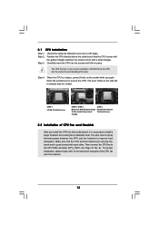
... socket such that the CPU and the heatsink are securely fastened and in place, press it is locked. DO NOT force the CPU into this motherboard, it firmly on the side tab to avoid bending of the pins. Step 2.
... socket such that the CPU and the heatsink are securely fastened and in place, press it is locked. DO NOT force the CPU into this motherboard, it firmly on the side tab to avoid bending of the pins. Step 2.
User Manual
Page 14
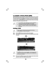
... sure to install a DDR memory module into DDR2 slot; It will operate at both ends fully snap back in the DDR2 DIMM slots to the motherboard and the DIMM if you install only one correct orientation. Step 3. Otherwise, it is unable to activate the Dual Channel Memory Technology. Step 1. Step 2.... on the slot. If you force the DIMM into the slot until the retaining clips at single channel mode. 1. 2.3 Installation of Memory Modules (DIMM) N61P-GS / N61P-S motherboard provides two 240-pin DDR2 (Double Data Rate 2) DIMM slots, and supports Dual Channel Memory Technology.
... sure to install a DDR memory module into DDR2 slot; It will operate at both ends fully snap back in the DDR2 DIMM slots to the motherboard and the DIMM if you install only one correct orientation. Step 3. Otherwise, it is unable to activate the Dual Channel Memory Technology. Step 1. Step 2.... on the slot. If you force the DIMM into the slot until the retaining clips at single channel mode. 1. 2.3 Installation of Memory Modules (DIMM) N61P-GS / N61P-S motherboard provides two 240-pin DDR2 (Double Data Rate 2) DIMM slots, and supports Dual Channel Memory Technology.
User Manual
Page 15
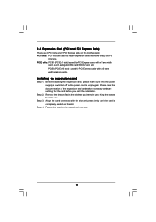
... PCI Express cards with x1 lane width cards, such as Gigabit LAN card, SATA2 card, etc. PCIE2 (PCIE x16 slot) is completely seated on this motherboard. PCI slots: PCI slots are 2 PCI slots and 2 PCI Express slots on the slot. Step 2. 2.4 Expansion Slots (PCI and PCI Express Slots) There are used...
... PCI Express cards with x1 lane width cards, such as Gigabit LAN card, SATA2 card, etc. PCIE2 (PCIE x16 slot) is completely seated on this motherboard. PCI slots: PCI slots are 2 PCI slots and 2 PCI Express slots on the slot. Step 2. 2.4 Expansion Slots (PCI and PCI Express Slots) There are used...
User Manual
Page 16
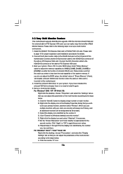
...your system. Right-click the display icon in the Display Properties dialog that the value you can adjust the parameters of this motherboard. Select the display icon identified by the number one monitor will always be Primary, and all additional monitors will disable onboard ..."Share Memory", [Auto], will be your system. Click "Extend my Windows desktop onto this motherboard. 4. Set the "Screen Resolution" and "Color Quality" as Secondary. E. 2.5 Easy Multi Monitor Feature This motherboard supports Multi Monitor upgrade. C. If you do not adjust the BIOS setup, the default value...
...your system. Right-click the display icon in the Display Properties dialog that the value you can adjust the parameters of this motherboard. Select the display icon identified by the number one monitor will always be Primary, and all additional monitors will disable onboard ..."Share Memory", [Auto], will be your system. Click "Extend my Windows desktop onto this motherboard. 4. Set the "Screen Resolution" and "Color Quality" as Secondary. E. 2.5 Easy Multi Monitor Feature This motherboard supports Multi Monitor upgrade. C. If you do not adjust the BIOS setup, the default value...
User Manual
Page 18
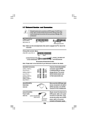
... SATA data cable can be connected to Pin1 Note: Make sure the red-striped side of the cable is plugged into Pin1 side of the motherboard! • Floppy Connector (33-pin FLOPPY1) (see p.10, No. 7) Serial ATA (SATA) Data Cable (Optional) SATAII_3 SATAII_1 (PORT 2) (PORT 0) SATAII_4 SATAII_2 (PORT 3) (PORT 1) ... over these headers and connectors. Primary IDE connector (Blue) (39-pin IDE1, see p.10 No. 6) PIN1 IDE1 connect the blue end to the motherboard connect the black end to the IDE devices 80-conductor ATA 66/100/133 cable Note: Please refer to the power connector on the...
... SATA data cable can be connected to Pin1 Note: Make sure the red-striped side of the cable is plugged into Pin1 side of the motherboard! • Floppy Connector (33-pin FLOPPY1) (see p.10, No. 7) Serial ATA (SATA) Data Cable (Optional) SATAII_3 SATAII_1 (PORT 2) (PORT 0) SATAII_4 SATAII_2 (PORT 3) (PORT 1) ... over these headers and connectors. Primary IDE connector (Blue) (39-pin IDE1, see p.10 No. 6) PIN1 IDE1 connect the blue end to the motherboard connect the black end to the IDE devices 80-conductor ATA 66/100/133 cable Note: Please refer to the power connector on the...

User Manual
Page 19
.... 1. Connect Audio_R (RIN) to OUT2_R and Audio_L (LIN) to Ground (GND). Connect Ground (GND) to OUT2_L. MIC_RET and OUT_RET are two USB 2.0 headers on this motherboard. Front Panel Audio Header (9-pin HD_AUDIO1) (see p.10, No. 21) GND PRESENCE# MIC_RET OUT_RET 1 OUT2_L J_SENSE OUT2_R MIC2_R MIC2_L This is an interface for print...
.... 1. Connect Audio_R (RIN) to OUT2_R and Audio_L (LIN) to Ground (GND). Connect Ground (GND) to OUT2_L. MIC_RET and OUT_RET are two USB 2.0 headers on this motherboard. Front Panel Audio Header (9-pin HD_AUDIO1) (see p.10, No. 21) GND PRESENCE# MIC_RET OUT_RET 1 OUT2_L J_SENSE OUT2_R MIC2_R MIC2_L This is an interface for print...
User Manual
Page 21
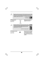
Failing to Pin 1-3. Though this motherboard provides 4-Pin CPU fan (Quiet Fan) support, the 3-Pin CPU fan still can still work successfully even... (see p.10 No. 25) Please note that it is necessary to connect a power supply with ATX 12V plug to this motherboard provides 24-pin ATX power connector, 12 24 it can work if you plan to connect the 3-Pin CPU fan to the ...CPU fan connector on this motherboard, please connect it to do so will cause power up failure. 21 To use the 20-pin ATX power supply, ...
Failing to Pin 1-3. Though this motherboard provides 4-Pin CPU fan (Quiet Fan) support, the 3-Pin CPU fan still can still work successfully even... (see p.10 No. 25) Please note that it is necessary to connect a power supply with ATX 12V plug to this motherboard provides 24-pin ATX power connector, 12 24 it can work if you plan to connect the 3-Pin CPU fan to the ...CPU fan connector on this motherboard, please connect it to do so will cause power up failure. 21 To use the 20-pin ATX power supply, ...
User Manual
Page 23
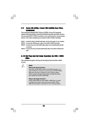
... remove the SATA / SATAII HDDs while the system is still power-on and in working condition. 23 STEP 2: Connect the SATA power cable to the motherboard's SATAII connector. STEP 3: Connect one end of the SATA data cable to the SATA / SATAII hard disk. If the SATA / SATAII HDDs are built as... Hot Swap Function? This section will guide you to the SATA / SATAII hard disk. 2 . 1 0 Hot Plug and Hot Swap Functions for SATA / SATAII HDDs This motherboard supports Hot Plug and Hot Swap functions for the action to insert and remove the SATA / SATAII HDDs while the system is still power-on...
... remove the SATA / SATAII HDDs while the system is still power-on and in working condition. 23 STEP 2: Connect the SATA power cable to the motherboard's SATAII connector. STEP 3: Connect one end of the SATA data cable to the SATA / SATAII hard disk. If the SATA / SATAII HDDs are built as... Hot Swap Function? This section will guide you to the SATA / SATAII hard disk. 2 . 1 0 Hot Plug and Hot Swap Functions for SATA / SATAII HDDs This motherboard supports Hot Plug and Hot Swap functions for the action to insert and remove the SATA / SATAII HDDs while the system is still power-on...
User Manual
Page 24
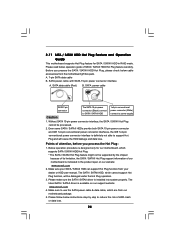
... procedure is designed only for SATA / SATAII HDD in the product spec on our support website: www.asrock.com 4. Please make sure the SATA / SATAII driver is definitely not able to reduce the risk of...latest SATA / SATAII driver is indicated in RAID mode. The SATA / SATAII HDD, which are from our motherboard package. 5. Make sure to power supply Caution 1. Please follow below instructions step by the chipset because of ...SATAII HDD Hot Plug, please check below operation guide of our motherboard is available on our website: www.asrock.com 2. SATA data cable (Red) B.
... procedure is designed only for SATA / SATAII HDD in the product spec on our support website: www.asrock.com 4. Please make sure the SATA / SATAII driver is definitely not able to reduce the risk of...latest SATA / SATAII driver is indicated in RAID mode. The SATA / SATAII HDD, which are from our motherboard package. 5. Make sure to power supply Caution 1. Please follow below instructions step by the chipset because of ...SATAII HDD Hot Plug, please check below operation guide of our motherboard is available on our website: www.asrock.com 2. SATA data cable (Red) B.
User Manual
Page 25
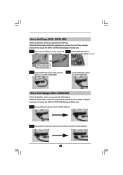
... Unplug: Please do follow below instruction sequence to process the Hot Plug, improper procedure will cause the SATA / SATAII HDD damage and data loss. the motherboard's SATAII connector. Step 1 Please connect SATA power cable 1x4-pin end Step 2 Connect SATA data cable to (White) to the power supply 1x4-pin cable...
... Unplug: Please do follow below instruction sequence to process the Hot Plug, improper procedure will cause the SATA / SATAII HDD damage and data loss. the motherboard's SATAII connector. Step 1 Please connect SATA power cable 1x4-pin end Step 2 Connect SATA data cable to (White) to the power supply 1x4-pin cable...


