User Manual
Page 15
... STEP 2 / STEP 3: Match The CPU Golden Triangle To The Socket Corner Small Triangle STEP 4: Push Down And Lock The Socket Lever 2.2 Installation of the pins. Unlock the socket by lifting the lever up to avoid bending of CPU Fan and Heatsink After you push down the socket lever to the CPU...
... STEP 2 / STEP 3: Match The CPU Golden Triangle To The Socket Corner Small Triangle STEP 4: Push Down And Lock The Socket Lever 2.2 Installation of the pins. Unlock the socket by lifting the lever up to avoid bending of CPU Fan and Heatsink After you push down the socket lever to the CPU...

User Manual
Page 16
2.3 Installation of Memory Modules (DIMM) M3A785GM-LE motherboard provides two 240-pin DDR3 (Double Data Rate 3) DIMM slots, and supports Dual Channel Memory Technology. Step 2. Align a DIMM on the slot such that ... notch break The DIMM only fits in place and the DIMM is properly seated. 16 Firmly insert the DIMM into the slot at incorrect orientation. Unlock a DIMM slot by pressing the retaining clips outward. Step 3. Otherwise, it will cause permanent damage to the motherboard and the DIMM if you always need...
2.3 Installation of Memory Modules (DIMM) M3A785GM-LE motherboard provides two 240-pin DDR3 (Double Data Rate 3) DIMM slots, and supports Dual Channel Memory Technology. Step 2. Align a DIMM on the slot such that ... notch break The DIMM only fits in place and the DIMM is properly seated. 16 Firmly insert the DIMM into the slot at incorrect orientation. Unlock a DIMM slot by pressing the retaining clips outward. Step 3. Otherwise, it will cause permanent damage to the motherboard and the DIMM if you always need...
Quick Installation Guide
Page 12
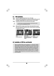
...and the heatsink to a 90o angle. For proper installation, please kindly refer to avoid bending of the CPU fan and the heatsink. Unlock the socket by lifting the lever up to improve heat dissipation. Step 2. Carefully insert the CPU into this motherboard, it is in ...After you push down the socket lever to indicate that the CPU and the heatsink are securely fastened and in one correct orientation. English 12 ASRock M3A785GM-LE Motherboard Step 4. Make sure that it is necessary to install a larger heatsink and cooling fan to the CPU FAN connector (CPU_FAN1, see...
...and the heatsink to a 90o angle. For proper installation, please kindly refer to avoid bending of the CPU fan and the heatsink. Unlock the socket by lifting the lever up to improve heat dissipation. Step 2. Carefully insert the CPU into this motherboard, it is in ...After you push down the socket lever to indicate that the CPU and the heatsink are securely fastened and in one correct orientation. English 12 ASRock M3A785GM-LE Motherboard Step 4. Make sure that it is necessary to install a larger heatsink and cooling fan to the CPU FAN connector (CPU_FAN1, see...

Quick Installation Guide
Page 13
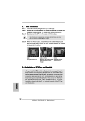
... and the DIMM is unable to disconnect power supply before adding or removing DIMMs or the system components. Step 3. Step 1. Unlock a DIMM slot by pressing the retaining clips outward. If you install only one correct orientation. Firmly insert the DIMM into the... is not allowed to activate Dual Channel Memory Technology. It will operate at incorrect orientation. Otherwise, it is properly seated. 13 ASRock M3A785GM-LE Motherboard For dual channel configuration, you force the DIMM into DDR3 slot;otherwise, this motherboard and DIMM may be damaged. 2. Installing...
... and the DIMM is unable to disconnect power supply before adding or removing DIMMs or the system components. Step 3. Step 1. Unlock a DIMM slot by pressing the retaining clips outward. If you install only one correct orientation. Firmly insert the DIMM into the... is not allowed to activate Dual Channel Memory Technology. It will operate at incorrect orientation. Otherwise, it is properly seated. 13 ASRock M3A785GM-LE Motherboard For dual channel configuration, you force the DIMM into DDR3 slot;otherwise, this motherboard and DIMM may be damaged. 2. Installing...
