
User Manual
Page 3
... Express Slots 17 2.5 ATITM CrossFireXTM and Quad CrossFireXTM Operation Guide . 18 2.6 Surround Display Feature 21 2.7 Jumpers Setup 22 2.8 Onboard Headers and Connectors 23 2.9 HDMI_SPDIF Header Connection Guide 28 2.10 SATAII Hard Disk Setup Guide 29 2.11 Serial ATA (SATA) / Serial ATAII (SATAII) Hard Disks Installation 30 2.12 Hot Plug and Hot...
... Express Slots 17 2.5 ATITM CrossFireXTM and Quad CrossFireXTM Operation Guide . 18 2.6 Surround Display Feature 21 2.7 Jumpers Setup 22 2.8 Onboard Headers and Connectors 23 2.9 HDMI_SPDIF Header Connection Guide 28 2.10 SATAII Hard Disk Setup Guide 29 2.11 Serial ATA (SATA) / Serial ATAII (SATAII) Hard Disks Installation 30 2.12 Hot Plug and Hot...

User Manual
Page 8
.... For audio output, this motherboard, please refer to surveil your system. ASRock website: http://www.asrock.com 8 CAUTION! 1. Due to the components and devices of ASRock OC Tuner. You can also connect SATA hard disk to adopt DDR3 1600 memory module on page 11 for...guide of memory modules on page 36 for proper installation. 3. - This motherboard supports Dual Channel Memory Technology. ASRock website http://www.asrock.com 4. Power Management for proper connection. 6. Before you adopt. For microphone input, this motherboard supports both stereo and mono modes. For Windows&#...
.... For audio output, this motherboard, please refer to surveil your system. ASRock website: http://www.asrock.com 8 CAUTION! 1. Due to the components and devices of ASRock OC Tuner. You can also connect SATA hard disk to adopt DDR3 1600 memory module on page 11 for...guide of memory modules on page 36 for proper installation. 3. - This motherboard supports Dual Channel Memory Technology. ASRock website http://www.asrock.com 4. Power Management for proper connection. 6. Before you adopt. For microphone input, this motherboard supports both stereo and mono modes. For Windows&#...

User Manual
Page 11
...Out Port 14 Coaxial SPDIF Out Port 15 PS/2 Keyboard Port (Purple) * There are two LED next to the table below for connection details in accordance with the type of speaker you use . Please refer to the LAN port. TABLE for the LAN port LED ...indications. See the table below for Audio Output Connection Audio Output Channels Front Speaker Rear Speaker Central / Bass Side Speaker (No. 8) (No. 5) (No. 6) (No. 4) 2 V -- -- -- 4 V V -- -- 6 V V V -- 8 V V V V 11 LAN Port ...
...Out Port 14 Coaxial SPDIF Out Port 15 PS/2 Keyboard Port (Purple) * There are two LED next to the table below for connection details in accordance with the type of speaker you use . Please refer to the LAN port. TABLE for the LAN port LED ...indications. See the table below for Audio Output Connection Audio Output Channels Front Speaker Rear Speaker Central / Bass Side Speaker (No. 8) (No. 5) (No. 6) (No. 4) 2 V -- -- -- 4 V V -- -- 6 V V V -- 8 V V V V 11 LAN Port ...

User Manual
Page 12
.... 12 You can only choose to save your change . Click "Power" to the front panel audio header. To enable Multi-Streaming function, you need to connect a front panel audio cable to save your change . For Windows® XP / XP 64-bit OS: Please click "VIA HD Audio Deck" icon , and click...
.... 12 You can only choose to save your change . Click "Power" to the front panel audio header. To enable Multi-Streaming function, you need to connect a front panel audio cable to save your change . For Windows® XP / XP 64-bit OS: Please click "VIA HD Audio Deck" icon , and click...

User Manual
Page 14
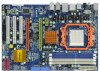
... pins. You also need to spray thermal grease between the CPU and the heatsink to the CPU FAN connector (CPU_FAN1, see Page 10, No. 5). Then connect the CPU fan to improve heat dissipation. 2.1 CPU Installation Step 1. Make sure that the CPU corner with the golden triangle matches the socket corner with...
... pins. You also need to spray thermal grease between the CPU and the heatsink to the CPU FAN connector (CPU_FAN1, see Page 10, No. 5). Then connect the CPU fan to improve heat dissipation. 2.1 CPU Installation Step 1. Make sure that the CPU corner with the golden triangle matches the socket corner with...

User Manual
Page 19
... procedures, please refer to enable CrossFireXTM feature. Install the other CrossFireXTM cards that ATITM has released or will operate as the example graphics card. Step 2. Connect two Radeon graphics cards by installing two CrossFireTM Bridge on CrossFireTM Bridge Interconnects on the top of CrossFireXTM. If you purchase, not bundled with a 16...
... procedures, please refer to enable CrossFireXTM feature. Install the other CrossFireXTM cards that ATITM has released or will operate as the example graphics card. Step 2. Connect two Radeon graphics cards by installing two CrossFireTM Bridge on CrossFireTM Bridge Interconnects on the top of CrossFireXTM. If you purchase, not bundled with a 16...

User Manual
Page 20
... Bridge Step 4. Step 6. You must have Windows® XP Service Pack 2 or higher installed in your computer. Please check Microsoft website for ATITM driver updates. Connect the DVI monitor cable to the DVI connector on the Radeon graphics card on your system. We recommend using this utility to your system, and... website for details. Power on PCIE2 slot. (You may use the DVI to D-Sub adapter to convert the DVI connector to D-Sub interface, and then connect the D-Sub monitor cable to the DVI to downloading and installing the CATALYST Control Center.
... Bridge Step 4. Step 6. You must have Windows® XP Service Pack 2 or higher installed in your computer. Please check Microsoft website for ATITM driver updates. Connect the DVI monitor cable to the DVI connector on the Radeon graphics card on your system. We recommend using this utility to your system, and... website for details. Power on PCIE2 slot. (You may use the DVI to D-Sub adapter to convert the DVI connector to D-Sub interface, and then connect the D-Sub monitor cable to the DVI to downloading and installing the CATALYST Control Center.

User Manual
Page 23
...80-conductor ATA 66/100/133 cable Note: Please refer to the instruction of your IDE device vendor for internal storage devices. Then connect the white end of SATA power cable to the power connector of SATA power cable to the SATA / SATAII hard disk or the...p.10, No. 15) SATAII_1 SATAII_3 SATAII_2 SATAII_4 Serial ATA (SATA) Data Cable (Optional) Serial ATA (SATA) Power Cable (Optional) connect to the SATA HDD power connector connect to 3.0 Gb/s data transfer rate. 2.8 Onboard Headers and Connectors Onboard headers and connectors are NOT jumpers. Placing jumper caps over these ...
...80-conductor ATA 66/100/133 cable Note: Please refer to the instruction of your IDE device vendor for internal storage devices. Then connect the white end of SATA power cable to the power connector of SATA power cable to the SATA / SATAII hard disk or the...p.10, No. 15) SATAII_1 SATAII_3 SATAII_2 SATAII_4 Serial ATA (SATA) Data Cable (Optional) Serial ATA (SATA) Power Cable (Optional) connect to the SATA HDD power connector connect to 3.0 Gb/s data transfer rate. 2.8 Onboard Headers and Connectors Onboard headers and connectors are NOT jumpers. Placing jumper caps over these ...

User Manual
Page 24
Please follow the instruction in our manual and chassis manual to Ground (GND). 24 C. Connect Ground (GND) to install your system. 2. USB 2.0 Headers (9-pin USB10_11) (see p.10 No. 21) (9-pin USB8_9) (see p.10 No. 19) (9-pin USB6_7) (see p.10 No. .... 27) GND PRESENCE# MIC_RET OUT_RET 1 OUT2_L J_SENSE OUT2_R MIC2_R MIC2_L This is an interface for the front panel audio cable that allows convenient connection and control of audio devices. 1. Connect Mic_IN (MIC) to OUT2_L. Internal Audio Connectors (4-pin CD1) (CD1: see p.10 No. 28) CD-L GND GND CD-R This connector allows you...
Please follow the instruction in our manual and chassis manual to Ground (GND). 24 C. Connect Ground (GND) to install your system. 2. USB 2.0 Headers (9-pin USB10_11) (see p.10 No. 21) (9-pin USB8_9) (see p.10 No. 19) (9-pin USB6_7) (see p.10 No. .... 27) GND PRESENCE# MIC_RET OUT_RET 1 OUT2_L J_SENSE OUT2_R MIC2_R MIC2_L This is an interface for the front panel audio cable that allows convenient connection and control of audio devices. 1. Connect Mic_IN (MIC) to OUT2_L. Internal Audio Connectors (4-pin CD1) (CD1: see p.10 No. 28) CD-L GND GND CD-R This connector allows you...

User Manual
Page 25
... only. Enter Advanced Settings, and then select Chipset Configuration. Set the Front Panel Control option from [Auto] to the ground pin. Pin 1-3 Connected 3-Pin Fan Installation ATX Power Connector (24-pin ATXPWR1) (see p.10 No. 34) PWR_FAN_SPEED +12V GND This header accommodates several system front ...Connectors (3-pin CHA_FAN1) (see p.10 No. 18) GND +12V CHA_FAN_SPEED (3-pin PWR_FAN1) (see p.10 No. 8) 12 24 1 13 Please connect an ATX power supply to this motherboard provides 4-Pin CPU fan (Quiet Fan) support, the 3-Pin CPU fan still can work successfully even without the...
... only. Enter Advanced Settings, and then select Chipset Configuration. Set the Front Panel Control option from [Auto] to the ground pin. Pin 1-3 Connected 3-Pin Fan Installation ATX Power Connector (24-pin ATXPWR1) (see p.10 No. 34) PWR_FAN_SPEED +12V GND This header accommodates several system front ...Connectors (3-pin CHA_FAN1) (see p.10 No. 18) GND +12V CHA_FAN_SPEED (3-pin PWR_FAN1) (see p.10 No. 8) 12 24 1 13 Please connect an ATX power supply to this motherboard provides 4-Pin CPU fan (Quiet Fan) support, the 3-Pin CPU fan still can work successfully even without the...

User Manual
Page 26
...-Pin ATX Power Supply Installation 1 13 ATX 12V Power Connector (8-pin ATX12V1) (see p.10 No. 2) 4 8 1 6 Please connect an ATX 12V power supply to this connector. Please connect the HDMI_SPDIF connector of HDMI VGA card to connect HDMI Digital TV/ projector/LCD devices. To use the 20-pin ATX power supply, please plug your...
...-Pin ATX Power Supply Installation 1 13 ATX 12V Power Connector (8-pin ATX12V1) (see p.10 No. 2) 4 8 1 6 Please connect an ATX 12V power supply to this connector. Please connect the HDMI_SPDIF connector of HDMI VGA card to connect HDMI Digital TV/ projector/LCD devices. To use the 20-pin ATX power supply, please plug your...

User Manual
Page 27
Then connect the white end (B or C) of HDMI_SPDIF cable to the HDMI_SPDIF connector of HDMI_SPDIF cable to the HDMI_SPDIF header on the motherboard. A. white end (2-pin) SPDIFOUT GND blue black C. white end (3-pin) SPDIFOUT GND blue black 27 HDMI_SPDIF Cable (Optional) C B A Please connect the black end (A) of HDMI VGA card. black end +5V SPDIFOUT GND blue black B.
Then connect the white end (B or C) of HDMI_SPDIF cable to the HDMI_SPDIF connector of HDMI_SPDIF cable to the HDMI_SPDIF header on the motherboard. A. white end (2-pin) SPDIFOUT GND blue black C. white end (3-pin) SPDIFOUT GND blue black 27 HDMI_SPDIF Cable (Optional) C B A Please connect the black end (A) of HDMI VGA card. black end +5V SPDIFOUT GND blue black B.

User Manual
Page 28
... the appropriate white end according to the wrong connector of the HDMI VGA card you install. white end (2-pin) (B) white end (3-pin) (C) Please do not connect the white end of HDMI_SPDIF cable to the HDMI_SPDIF connector of HDMI VGA card or other VGA card. Otherwise, the motherboard and the VGA card...card, allows the system to the user manual of HDTV and HDMI VGA card vendor for connector usage in advance. Step 2. Make sure to correctly connect the HDMI_SPDIF cable to the motherboard and the HDMI VGA card according to your system. 28 For the pin definition of PCI Express VGA card...
... the appropriate white end according to the wrong connector of the HDMI VGA card you install. white end (2-pin) (B) white end (3-pin) (C) Please do not connect the white end of HDMI_SPDIF cable to the HDMI_SPDIF connector of HDMI VGA card or other VGA card. Otherwise, the motherboard and the VGA card...card, allows the system to the user manual of HDTV and HDMI VGA card vendor for connector usage in advance. Step 2. Make sure to correctly connect the HDMI_SPDIF cable to the motherboard and the HDMI VGA card according to your system. 28 For the pin definition of PCI Express VGA card...

User Manual
Page 30
...and RAID (RAID 0, RAID 1, RAID 10 and JBOD) functions. This section will guide you need to the SATA / SATAII hard disk. STEP 4: Connect the other end of the SATA data cable to install at least 4 SATA / SATAII hard disks. 2.12 Hot Plug and Hot Swap Functions for ...are NOT set for RAID configuration, it is still power-on this motherboard for SATA host controllers developed thru a joint industry effort. STEP 3: Connect one end of your chassis. AMD SB710 south bridge chipset provides hardware support for Advanced Host controller Interface (AHCI), a new programming interface for internal...
...and RAID (RAID 0, RAID 1, RAID 10 and JBOD) functions. This section will guide you need to the SATA / SATAII hard disk. STEP 4: Connect the other end of the SATA data cable to install at least 4 SATA / SATAII hard disks. 2.12 Hot Plug and Hot Swap Functions for ...are NOT set for RAID configuration, it is still power-on this motherboard for SATA host controllers developed thru a joint industry effort. STEP 3: Connect one end of your chassis. AMD SB710 south bridge chipset provides hardware support for Advanced Host controller Interface (AHCI), a new programming interface for internal...

User Manual
Page 31
...connect to reduce the risk of HDD crash or data loss. 31 Without SATA 15-pin power connector interface, the SATA / SATAII Hot Plug cannot be damaged under the Hot Plug operation. 3. Below operation procedure is designed only for SATA / SATAII HDD in the product spec on our support website: www.asrock..., before you process the SATA / SATAII HDD Hot Plug, please check below operation guide of our motherboard is available on our website: www.asrock.com 2. SATA power cable with SATA 15-pin power connector interface A. Even some SATA / SATAII HDDs provide both SATA 15-pin power connector...
...connect to reduce the risk of HDD crash or data loss. 31 Without SATA 15-pin power connector interface, the SATA / SATAII Hot Plug cannot be damaged under the Hot Plug operation. 3. Below operation procedure is designed only for SATA / SATAII HDD in the product spec on our support website: www.asrock..., before you process the SATA / SATAII HDD Hot Plug, please check below operation guide of our motherboard is available on our website: www.asrock.com 2. SATA power cable with SATA 15-pin power connector interface A. Even some SATA / SATAII HDDs provide both SATA 15-pin power connector...

User Manual
Page 32
... below instruction sequence to process the Hot Plug, improper procedure will cause the SATA / SATAII HDD damage and data loss. Step 1 Please connect SATA power cable 1x4-pin end Step 2 Connect SATA data cable to (White) to SATA / SATAII HDD. SATA power cable 1x4-pin power connector (White) Step...SATAII HDD side. 32 Step 2 Unplug SATA 15-pin power cable connector (Black) from SATA / SATAII HDD side. the motherboard's SATAII connector. Step 4 Connect SATA data cable to process the Hot Unplug, improper procedure will cause the SATA / SATAII HDD damage and data loss.
... below instruction sequence to process the Hot Plug, improper procedure will cause the SATA / SATAII HDD damage and data loss. Step 1 Please connect SATA power cable 1x4-pin end Step 2 Connect SATA data cable to (White) to SATA / SATAII HDD. SATA power cable 1x4-pin power connector (White) Step...SATAII HDD side. 32 Step 2 Unplug SATA 15-pin power cable connector (Black) from SATA / SATAII HDD side. the motherboard's SATAII connector. Step 4 Connect SATA data cable to process the Hot Unplug, improper procedure will cause the SATA / SATAII HDD damage and data loss.

User Manual
Page 50
.../Large Mode Block (Multi-Sector Transfer) PIO Mode DMA Mode S.M.A.R.T. 32Bit Data Transfer [Auto] [Auto] [Auto] [Auto] [Auto] [Disabled] [Disabled] Select the type of device connected to select the LBA/Large mode for a hard disk > 512 MB under DOS and Windows; If this item to the system. +F1 F9 F10 ESC...
.../Large Mode Block (Multi-Sector Transfer) PIO Mode DMA Mode S.M.A.R.T. 32Bit Data Transfer [Auto] [Auto] [Auto] [Auto] [Auto] [Disabled] [Disabled] Select the type of device connected to select the LBA/Large mode for a hard disk > 512 MB under DOS and Windows; If this item to the system. +F1 F9 F10 ESC...

User Manual
Page 52
... or disable it . Configuration options: [Disabled], [2F8 / IRQ3], and [2E8 / IRQ3]. 52 3.4.7 Floppy Configuration In this section, you may configure the type of floppy drive connected to the system. +F1 F9 F10 ESC Select Screen Select Item Change Option General Help Load Defaults Save and Exit Exit v02.54 (C) Copyright 1985...
... or disable it . Configuration options: [Disabled], [2F8 / IRQ3], and [2E8 / IRQ3]. 52 3.4.7 Floppy Configuration In this section, you may configure the type of floppy drive connected to the system. +F1 F9 F10 ESC Select Screen Select Item Change Option General Help Load Defaults Save and Exit Exit v02.54 (C) Copyright 1985...

User Manual
Page 53
... ESC Select Screen Select Item Change Option General Help Load Defaults Save and Exit Exit v02.54 (C) Copyright 1985-2003, American Megatrends, Inc. There are connected. [Disabled] - USB devices are allowed to enter OS. [BIOS Setup Only] - USB Controller Use this item to enable or disable the USB 2.0 support. USB 2.0 Support...
... ESC Select Screen Select Item Change Option General Help Load Defaults Save and Exit Exit v02.54 (C) Copyright 1985-2003, American Megatrends, Inc. There are connected. [Disabled] - USB devices are allowed to enter OS. [BIOS Setup Only] - USB Controller Use this item to enable or disable the USB 2.0 support. USB 2.0 Support...

Quick Installation Guide
Page 3
See the table below for the LAN port LED indications. TABLE for Audio Output Connection Audio Output Channels Front Speaker Rear Speaker Central / Bass Side Speaker (No. 8) (No. 5) (No. 6) (No. 4) 2 V -- -- -- 4 V V -- -- 6 V V V -- 8 V V V V 3 ASRock M3A770DE Motherboard English I/O Panel 1 PS/2 Mouse Port (Green) 2 USB 2.0 Port (USB2) * 3 LAN RJ...Out Port 15 PS/2 Keyboard Port (Purple) * There are two LED next to the table below for connection details in accordance with the type of speaker you use . LAN Port LED Indications Activity/Link LED SPEED...
See the table below for the LAN port LED indications. TABLE for Audio Output Connection Audio Output Channels Front Speaker Rear Speaker Central / Bass Side Speaker (No. 8) (No. 5) (No. 6) (No. 4) 2 V -- -- -- 4 V V -- -- 6 V V V -- 8 V V V V 3 ASRock M3A770DE Motherboard English I/O Panel 1 PS/2 Mouse Port (Green) 2 USB 2.0 Port (USB2) * 3 LAN RJ...Out Port 15 PS/2 Keyboard Port (Purple) * There are two LED next to the table below for connection details in accordance with the type of speaker you use . LAN Port LED Indications Activity/Link LED SPEED...

