
User Manual
Page 3
...33 3.5.1 Boot Settings Configuration 34 3.6 Security Screen 35 3.7 Exit Screen 36 3 Introduction 5 1.1 Package Contents 5 1.2 Specifications 6 1.3 Motherboard Layout 9 1.4 ASRock 8CH I/O 10 2 . Contents 1 . Installation 10 Pre-installation Precautions 10 2.1 CPU Installation 11 2.2 Installation of CPU Fan and Heatsink 11 2.3 Installation of... Slots 13 2.5 Jumpers Setup 15 2.6 Onboard Headers and Connectors 16 2.7 Serial ATA (SATA) Hard Disks Installation 19 2.8 Making a SATA Driver Diskette For SATA Operation in "RAID" Mode 20 2.9 SATA Operating in "non-RAID" Mode 20 3 .
...33 3.5.1 Boot Settings Configuration 34 3.6 Security Screen 35 3.7 Exit Screen 36 3 Introduction 5 1.1 Package Contents 5 1.2 Specifications 6 1.3 Motherboard Layout 9 1.4 ASRock 8CH I/O 10 2 . Contents 1 . Installation 10 Pre-installation Precautions 10 2.1 CPU Installation 11 2.2 Installation of CPU Fan and Heatsink 11 2.3 Installation of... Slots 13 2.5 Jumpers Setup 15 2.6 Onboard Headers and Connectors 16 2.7 Serial ATA (SATA) Hard Disks Installation 19 2.8 Making a SATA Driver Diskette For SATA Operation in "RAID" Mode 20 2.9 SATA Operating in "non-RAID" Mode 20 3 .
User Manual
Page 5
... will be available on ASRock website as well. ASRock website http://www.asrock.com 1.1 Package Contents 1 x ASRock K8Upgrade-1689 Motherboard (ATX Form Factor: 7.5-in x 12.0-in, 19.1 cm x 30.5 cm) 1 x ASRock K8Upgrade-1689 Quick Installation Guide 1 x ASRock K8Upgrade-1689 Support CD 1 x Ultra ATA 66/100/133 IDE Ribbon Cable (80-conductor) 1 x 3.5-in Floppy Drive Ribbon Cable 1 x Serial ATA (SATA) Data Cable (Optional) 1 x Serial...
... will be available on ASRock website as well. ASRock website http://www.asrock.com 1.1 Package Contents 1 x ASRock K8Upgrade-1689 Motherboard (ATX Form Factor: 7.5-in x 12.0-in, 19.1 cm x 30.5 cm) 1 x ASRock K8Upgrade-1689 Quick Installation Guide 1 x ASRock K8Upgrade-1689 Support CD 1 x Ultra ATA 66/100/133 IDE Ribbon Cable (80-conductor) 1 x 3.5-in Floppy Drive Ribbon Cable 1 x Serial ATA (SATA) Data Cable (Optional) 1 x Serial...

User Manual
Page 6
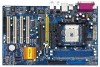
...ATA 133 / Ultra DMA Mode 6 IDE2: ATA 133 / Ultra DMA Mode 6 Supports up to 4 IDE Devices Serial ATA: 2 x SATA Connectors Supports up to 2 SATA Devices at 1.5Gb/s Data Transfer Rate Floppy Port: Supports up to 2 Floppy Disk Drives Audio: 7.1 channels AC'97 Audio LAN: Speed:... 802.3u (10/100 Ethernet), Supports Wake-On-LAN Hardware Monitor: CPU Temperature Sensing Motherboard Temperature Sensing CPU Overheat Shutdown to Protect CPU Life (ASRock...
...ATA 133 / Ultra DMA Mode 6 IDE2: ATA 133 / Ultra DMA Mode 6 Supports up to 4 IDE Devices Serial ATA: 2 x SATA Connectors Supports up to 2 SATA Devices at 1.5Gb/s Data Transfer Rate Floppy Port: Supports up to 2 Floppy Disk Drives Audio: 7.1 channels AC'97 Audio LAN: Speed:... 802.3u (10/100 Ethernet), Supports Wake-On-LAN Hardware Monitor: CPU Temperature Sensing Motherboard Temperature Sensing CPU Overheat Shutdown to Protect CPU Life (ASRock...

User Manual
Page 16
...IDE2, see p.8 No. 9) PIN1 IDE1 PIN1 IDE2 connect the blue end to the motherboard connect the black end to 1.5 Gb/s data transfer rate. The current SATA interface allows up to the IDE devices 80-conductor ATA 66/100/133 cable Note: If you use only one IDE device on the motherboard... cable is plugged into Pin1 side of your hard disk drive to the primary IDE connector (IDE1, blue) and CD-ROM to the SATA hard disk or the SATA connector on this motherboard, please set the IDE device as "Master". 2.6 Onboard Headers and Connectors Onboard headers and connectors are NOT jumpers. ...
...IDE2, see p.8 No. 9) PIN1 IDE1 PIN1 IDE2 connect the blue end to the motherboard connect the black end to 1.5 Gb/s data transfer rate. The current SATA interface allows up to the IDE devices 80-conductor ATA 66/100/133 cable Note: If you use only one IDE device on the motherboard... cable is plugged into Pin1 side of your hard disk drive to the primary IDE connector (IDE1, blue) and CD-ROM to the SATA hard disk or the SATA connector on this motherboard, please set the IDE device as "Master". 2.6 Onboard Headers and Connectors Onboard headers and connectors are NOT jumpers. ...

User Manual
Page 17
... to the power connector of the power supply. USB 2.0 Header (9-pin USB4_5) (see p.8 No. 17) USB_PWR P-6 P+6 GND DUMMY 1 GND P+7 P-7 USB_PWR ASRock 8CH I /O accommodates 4 default USB 2.0 ports. R MIC-POWER MIC This is available to support 2 additional USB 2.0 ports. If those USB 2.0 ports on the... I /O panel are not sufficient, this USB 2.0 header is an interface for front panel audio cable that allows convenient connection and control of SATA power cable to support 2 additional USB 2.0 ports. O U T- Front Panel Audio Header (9-pin AUDIO1) (see p.8 No. 24) IRTX +5V...
... to the power connector of the power supply. USB 2.0 Header (9-pin USB4_5) (see p.8 No. 17) USB_PWR P-6 P+6 GND DUMMY 1 GND P+7 P-7 USB_PWR ASRock 8CH I /O accommodates 4 default USB 2.0 ports. R MIC-POWER MIC This is available to support 2 additional USB 2.0 ports. If those USB 2.0 ports on the... I /O panel are not sufficient, this USB 2.0 header is an interface for front panel audio cable that allows convenient connection and control of SATA power cable to support 2 additional USB 2.0 ports. O U T- Front Panel Audio Header (9-pin AUDIO1) (see p.8 No. 24) IRTX +5V...

User Manual
Page 19
... one end of the SATA data cable to the motherboard's SATA connector. STEP 4: Connect the other end of the SATA data cable to the SATA hard disk. 1. They need different drivers during actual operation. 19 If you to use RAID 0, RAID 1, or JBOD functions on SATA, SATA HDDs must be operated ...in BIOS setup. 2.7 Serial ATA (SATA) Hard Disks Installation This motherboard supports Serial ATA (SATA) hard disks and RAID functions. STEP 2: Connect the SATA power cable to page 28 for details. Please refer to...
... one end of the SATA data cable to the motherboard's SATA connector. STEP 4: Connect the other end of the SATA data cable to the SATA hard disk. 1. They need different drivers during actual operation. 19 If you to use RAID 0, RAID 1, or JBOD functions on SATA, SATA HDDs must be operated ...in BIOS setup. 2.7 Serial ATA (SATA) Hard Disks Installation This motherboard supports Serial ATA (SATA) hard disks and RAID functions. STEP 2: Connect the SATA power cable to page 28 for details. Please refer to...

User Manual
Page 20
... press key, and then a window for proper configuration. Start to generate Serial ATA driver diskette [YN]?", press . WARNING! Once you have the SATA driver diskette ready, you may start to install Windows 2000 / Windows XP / Windows XP 64-bit on your system directly without setting the RAID configuration...in RAID mode, and you don't need to check the installation guide in the Support CD for boot devices selection appears. STEP 1: Insert the ASRock Support CD into your optical drive to boot your system. (Do NOT insert any floppy diskette into the floppy drive, and press . Please ...
... press key, and then a window for proper configuration. Start to generate Serial ATA driver diskette [YN]?", press . WARNING! Once you have the SATA driver diskette ready, you may start to install Windows 2000 / Windows XP / Windows XP 64-bit on your system directly without setting the RAID configuration...in RAID mode, and you don't need to check the installation guide in the Support CD for boot devices selection appears. STEP 1: Insert the ASRock Support CD into your optical drive to boot your system. (Do NOT insert any floppy diskette into the floppy drive, and press . Please ...
User Manual
Page 28
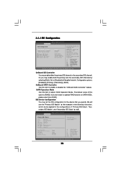
...instruction, which can be applied to the configurations of "Primary IDE Slave", "Secondary IDE Master", and "Secondary IDE Slave" as well. SATA Operation Mode Use this option is [RAID]. If you specify. IDE Device Configuration You may set the IDE configuration for the device that...will disable the both. Configuration options: [Disabled], [Primary], [Secondary], [Both]. The default value of device connected to operate RAID function on SATA HDDs, please select [non-RAID]. OnBoard IDE Controller You may enable both IDE Controllers. +F1 F9 F10 ESC Select Screen Select Item Change Option...
...instruction, which can be applied to the configurations of "Primary IDE Slave", "Secondary IDE Master", and "Secondary IDE Slave" as well. SATA Operation Mode Use this option is [RAID]. If you specify. IDE Device Configuration You may set the IDE configuration for the device that...will disable the both. Configuration options: [Disabled], [Primary], [Secondary], [Both]. The default value of device connected to operate RAID function on SATA HDDs, please select [non-RAID]. OnBoard IDE Controller You may enable both IDE Controllers. +F1 F9 F10 ESC Select Screen Select Item Change Option...
