User Manual
Page 3
... 26 2.15 Untied Overclocking Technology 26 3 . Contents 1 . Installation 12 Pre-installation Precautions 12 2.1 CPU Installation 13 2.2 Installation of CPU Fan and Heatsink 13 2.3 Installation of Memory Modules (DIMM 14 2.4 Expansion Slots (PCI Express, PCI, and HDMR Slots 15 2.5 Easy Multi Monitor Feature 16 2.6 Jumpers Setup 17 2.7 Onboard Headers and Connectors 18...
... 26 2.15 Untied Overclocking Technology 26 3 . Contents 1 . Installation 12 Pre-installation Precautions 12 2.1 CPU Installation 13 2.2 Installation of CPU Fan and Heatsink 13 2.3 Installation of Memory Modules (DIMM 14 2.4 Expansion Slots (PCI Express, PCI, and HDMR Slots 15 2.5 Easy Multi Monitor Feature 16 2.6 Jumpers Setup 17 2.7 Onboard Headers and Connectors 18...
User Manual
Page 6
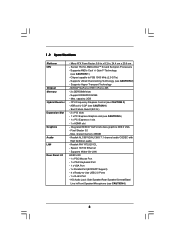
... 4) - capacity: 2GB - shared memory 256MB - HD Audio Jack: Side Speaker/Rear Speaker/Central/Bass/ Line in , 24.4 cm x 20.8 cm - Micro ATX Form Factor: 9.6-in x 8.2-in /Front Speaker/Microphone (see CAUTION 2) - Supports Hyper-Transport Technology - ASRock U-COP (see CAUTION 1) - Boot... 1 x PCI Express x1 slot - 1 x HDMR slot - Realtek ALC861VD/ALC883 7.1 channel audio CODEC with High Definition audio - 1.2 Specifications Platform CPU Chipset Memory Hybrid Booster Expansion Slot Graphics Audio LAN Rear Panel I /O - 1 x PS/2 Mouse Port - 1 x PS/2 Keyboard Port - 1 x VGA Port -...
... 4) - capacity: 2GB - shared memory 256MB - HD Audio Jack: Side Speaker/Rear Speaker/Central/Bass/ Line in , 24.4 cm x 20.8 cm - Micro ATX Form Factor: 9.6-in x 8.2-in /Front Speaker/Microphone (see CAUTION 2) - Supports Hyper-Transport Technology - ASRock U-COP (see CAUTION 1) - Boot... 1 x PCI Express x1 slot - 1 x HDMR slot - Realtek ALC861VD/ALC883 7.1 channel audio CODEC with High Definition audio - 1.2 Specifications Platform CPU Chipset Memory Hybrid Booster Expansion Slot Graphics Audio LAN Rear Panel I /O - 1 x PS/2 Mouse Port - 1 x PS/2 Keyboard Port - 1 x VGA Port -...

User Manual
Page 9
... Sempron 2500+ 512MB Single Channel* DX9.0 with WDDM Driver * If you use onboard VGA with total system memory size above . 9 1.3 Minimum Hardware Requirement Table for Windows® VistaTM Basic Logo For system integrators and users who purchase our motherboard and plan to 64MB. ...If you use onboard VGA with total system memory size 512MB and plan to submit Windows® VistaTM Basic logo, please adjust the shared memory size of onboard VGA to 128MB or above 512MB and plan to submit Windows® VistaTM Basic...
... Sempron 2500+ 512MB Single Channel* DX9.0 with WDDM Driver * If you use onboard VGA with total system memory size above . 9 1.3 Minimum Hardware Requirement Table for Windows® VistaTM Basic Logo For system integrators and users who purchase our motherboard and plan to 64MB. ...If you use onboard VGA with total system memory size 512MB and plan to submit Windows® VistaTM Basic logo, please adjust the shared memory size of onboard VGA to 128MB or above 512MB and plan to submit Windows® VistaTM Basic...

User Manual
Page 10
...45 ATXPWR1 ATX12V1 Socket 754 RAID RoHS NVIDIA GeForce 6100 / nForce 405 Chipset Super I/O 4Mb BIOS CD1 LAN PHY AUDIO CODEC 1 HD_AUDIO1 PCIE1 K8NF6G-VSTA PCI1 PCI EXPRESS PCI2 USB2.0 USB6_7 1 PCIE2 7.1CH HD HDMR1 GAME1 1 CMOS BATTERY CLRCMOS1 1 FLOPPY1 IR1 1 USB4_5 1 CHA_FAN1 PANEL 1 ... Jumper (CLRCMOS1) 3 184-pin DDR DIMM Slots (DDR1- 2) 17 Game Port Header (GAME1) 4 Primary SATAII Connector (SATAII_1, Red) 18 Flash Memory 5 Secondary SATAII Connector (SATAII_2, Red) 19 HDMR Slot (HDMR1) 6 Primary IDE Connector (IDE1, Blue) 20 Front Panel Audio Header (HD_AUDIO1) 7...
...45 ATXPWR1 ATX12V1 Socket 754 RAID RoHS NVIDIA GeForce 6100 / nForce 405 Chipset Super I/O 4Mb BIOS CD1 LAN PHY AUDIO CODEC 1 HD_AUDIO1 PCIE1 K8NF6G-VSTA PCI1 PCI EXPRESS PCI2 USB2.0 USB6_7 1 PCIE2 7.1CH HD HDMR1 GAME1 1 CMOS BATTERY CLRCMOS1 1 FLOPPY1 IR1 1 USB4_5 1 CHA_FAN1 PANEL 1 ... Jumper (CLRCMOS1) 3 184-pin DDR DIMM Slots (DDR1- 2) 17 Game Port Header (GAME1) 4 Primary SATAII Connector (SATAII_1, Red) 18 Flash Memory 5 Secondary SATAII Connector (SATAII_2, Red) 19 HDMR Slot (HDMR1) 6 Primary IDE Connector (IDE1, Blue) 20 Front Panel Audio Header (HD_AUDIO1) 7...

User Manual
Page 14
... DDR (Double Data Rate) DIMM slots. Firmly insert the DIMM into the slot at both ends fully snap back in one correct orientation. 2.3 Installation of Memory Modules (DIMM) This motherboard is properly seated. 14 Please make sure to the motherboard and the DIMM if you force the DIMM into the slot...
... DDR (Double Data Rate) DIMM slots. Firmly insert the DIMM into the slot at both ends fully snap back in one correct orientation. 2.3 Installation of Memory Modules (DIMM) This motherboard is properly seated. 14 Please make sure to the motherboard and the DIMM if you force the DIMM into the slot...

User Manual
Page 16
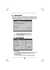
... VGA/DVI-D connector of Multi Monitor feature. Connect the DVI-D input monitor cable to set up a multi-monitor display. Enter "Share Memory" option to adjust the memory capability to [16MB], [32MB], [64MB], [128MB], or [256MB] to your system. Install the onboard VGA driver to enable the ...setup, the default value of this motherboard. 4. When you select is no need to display a large number on the I/O panel of "Share Memory", [Auto], will be designated as appropriate for details. 2. Press to apply these new values. With the internal onboard VGA and the external ...
... VGA/DVI-D connector of Multi Monitor feature. Connect the DVI-D input monitor cable to set up a multi-monitor display. Enter "Share Memory" option to adjust the memory capability to [16MB], [32MB], [64MB], [128MB], or [256MB] to your system. Install the onboard VGA driver to enable the ...setup, the default value of this motherboard. 4. When you select is no need to display a large number on the I/O panel of "Share Memory", [Auto], will be designated as appropriate for details. 2. Press to apply these new values. With the internal onboard VGA and the external ...

User Manual
Page 27
... the BIOS SETUP UTILITY to configure your screen. 3.1.1 BIOS Menu Bar The top of the screen has a menu bar with its test routines. The Flash Memory on the menu bar, and then press to locate and load the Operating System Security To set up the computer. You may also restart by...
... the BIOS SETUP UTILITY to configure your screen. 3.1.1 BIOS Menu Bar The top of the screen has a menu bar with its test routines. The Flash Memory on the menu bar, and then press to locate and load the Operating System Security To set up the computer. You may also restart by...

User Manual
Page 28
...BIOS SETUP UTILITY Main Advanced H/W Monitor Boot Security Exit System Overview System Time System Date [17:00:09] [Wed 07/12/2006] BIOS Version : K8NF6G-VSTA BIOS P1.0 Processor Type : AMD Athlon(tm) 64 Processor 3400+ (64bit supported) Processor Speed : 2200 MHz Microcode Update : F7A/3A L1 Cache Size... : 128KB L2 Cache Size : 512KB Total Memory DDR 1 DDR 2 : 256MB with 64MB shared memory : 256MB/166MHz (DDR333) : None Use [Enter], [TAB] or [SHIFT-TAB] to configure system Time. +Tab F1 F9 F10 ESC...
...BIOS SETUP UTILITY Main Advanced H/W Monitor Boot Security Exit System Overview System Time System Date [17:00:09] [Wed 07/12/2006] BIOS Version : K8NF6G-VSTA BIOS P1.0 Processor Type : AMD Athlon(tm) 64 Processor 3400+ (64bit supported) Processor Speed : 2200 MHz Microcode Update : F7A/3A L1 Cache Size... : 128KB L2 Cache Size : 512KB Total Memory DDR 1 DDR 2 : 256MB with 64MB shared memory : 256MB/166MHz (DDR333) : None Use [Enter], [TAB] or [SHIFT-TAB] to configure system Time. +Tab F1 F9 F10 ESC...
User Manual
Page 29
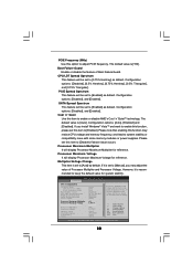
... (MHz) Boot Failure Guard CPU/LDT Spread Spectrum PCIE Spread Spectrum SATA Spread Spectrum Cool' n' Quiet Processor Maximum Multiplier Processor Maximum Voltage Multiplier/Voltage Change Memory Clock Flexibility Option CAS Latency TRAS TRP TRCD TRRD [Auto] [200] [100] [Enabled] [0.75% Hershey] [Enabled] [Enabled] [Auto] x11 1.550 V [Auto] [Auto] [Disabled] [Auto] [Auto...
... (MHz) Boot Failure Guard CPU/LDT Spread Spectrum PCIE Spread Spectrum SATA Spread Spectrum Cool' n' Quiet Processor Maximum Multiplier Processor Maximum Voltage Multiplier/Voltage Change Memory Clock Flexibility Option CAS Latency TRAS TRP TRCD TRRD [Auto] [200] [100] [Enabled] [0.75% Hershey] [Enabled] [Enabled] [Auto] x11 1.550 V [Auto] [Auto] [Disabled] [Auto] [Auto...
User Manual
Page 30
...CPU/LDT Spread Spectrum PCIE Spread Spectrum SATA Spread Spectrum Cool' n' Quiet Processor Maximum Multiplier Processor Maximum Voltage Multiplier/Voltage Change Processor Multiplier Processor Voltage Memory Clock Flexibility Option CAS Latency TRAS [Auto] [200] [100] [Enabled] [0.75% Hershey] [Enabled] [Enabled] [Auto] x11 1.550...this item to adjust PCIE frequency. Cool 'n' Quiet Use this item to system stability or compatibility issue with some memory modules or power supplies. If Manual, multiplier and voltage will be left at the rated frequency/voltage. Configuration ...
...CPU/LDT Spread Spectrum PCIE Spread Spectrum SATA Spread Spectrum Cool' n' Quiet Processor Maximum Multiplier Processor Maximum Voltage Multiplier/Voltage Change Processor Multiplier Processor Voltage Memory Clock Flexibility Option CAS Latency TRAS [Auto] [200] [100] [Enabled] [0.75% Hershey] [Enabled] [Enabled] [Auto] x11 1.550...this item to adjust PCIE frequency. Cool 'n' Quiet Use this item to system stability or compatibility issue with some memory modules or power supplies. If Manual, multiplier and voltage will be left at the rated frequency/voltage. Configuration ...

User Manual
Page 31
... when "Multiplier/Voltage Change" is set to [Manual]; However, for safety and system stability, it is set to adjust values for memory compatibility when it is not recommended to adjust the value of this item to adjust TRRD values. The default value is [Auto]. Configuration... options: [Auto], [2CLK], [3CLK], [4CLK], [5CLK], and [6CLK]. The default value is [Auto]. The range of memory accessing. otherwise, it will be set by the code using [Auto]. Processor Multiplier This item will show when "Multiplier/Voltage Change" is set to [Manual...
... when "Multiplier/Voltage Change" is set to [Manual]; However, for safety and system stability, it is set to adjust values for memory compatibility when it is not recommended to adjust the value of this item to adjust TRRD values. The default value is [Auto]. Configuration... options: [Auto], [2CLK], [3CLK], [4CLK], [5CLK], and [6CLK]. The default value is [Auto]. The range of memory accessing. otherwise, it will be set by the code using [Auto]. Processor Multiplier This item will show when "Multiplier/Voltage Change" is set to [Manual...

User Manual
Page 32
...[Auto], [8 bit], and [16 bit]. The default value is [Auto]. OnBoard LAN This allows you selecting CPU to NB link frequency. Share Memory This allows you select [Auto], the onboard HD Audio will switch the PCI Bus scanning order while searching for video card. Configuration options: [PCI], ...Auto], [Enabled] or [Disabled] for the onboard HD Audio feature. DRAM Voltage Use this feature is [PCI]. Bank Interleaving Interleaving allows memory accesses to be disabled when PCI Sound Card is plugged. Primary Graphics Adapter This item will be spread out over banks on the same ...
...[Auto], [8 bit], and [16 bit]. The default value is [Auto]. OnBoard LAN This allows you selecting CPU to NB link frequency. Share Memory This allows you select [Auto], the onboard HD Audio will switch the PCI Bus scanning order while searching for video card. Configuration options: [PCI], ...Auto], [Enabled] or [Disabled] for the onboard HD Audio feature. DRAM Voltage Use this feature is [PCI]. Bank Interleaving Interleaving allows memory accesses to be disabled when PCI Sound Card is plugged. Primary Graphics Adapter This item will be spread out over banks on the same ...

Quick Installation Guide
Page 2
... Connector (CPU_FAN1) 16 Clear CMOS Jumper (CLRCMOS1) 3 184-pin DDR DIMM Slots (DDR1- 2) 17 Game Port Header (GAME1) 4 Primary SATAII Connector (SATAII_1, Red) 18 Flash Memory 5 Secondary SATAII Connector (SATAII_2, Red) 19 HDMR Slot (HDMR1) 6 Primary IDE Connector (IDE1, Blue) 20 Front Panel Audio Header (HD_AUDIO1) 7 NVIDIA Single Chip 21 PCI...) 26 Serial Port Connector (COM1) 13 Chassis Speaker Header (SPEAKER 1) 27 754-Pin CPU Socket 14 Infrared Module Header (IR1) 28 CPU Heatsink Retention Module 2 ASRock K8NF6G-VSTA Motherboard
... Connector (CPU_FAN1) 16 Clear CMOS Jumper (CLRCMOS1) 3 184-pin DDR DIMM Slots (DDR1- 2) 17 Game Port Header (GAME1) 4 Primary SATAII Connector (SATAII_1, Red) 18 Flash Memory 5 Secondary SATAII Connector (SATAII_2, Red) 19 HDMR Slot (HDMR1) 6 Primary IDE Connector (IDE1, Blue) 20 Front Panel Audio Header (HD_AUDIO1) 7 NVIDIA Single Chip 21 PCI...) 26 Serial Port Connector (COM1) 13 Chassis Speaker Header (SPEAKER 1) 27 754-Pin CPU Socket 14 Infrared Module Header (IR1) 28 CPU Heatsink Retention Module 2 ASRock K8NF6G-VSTA Motherboard

Quick Installation Guide
Page 5
...Max. CPU Frequency Stepless Control (see CAUTION 2) - ASRock U-COP (see CAUTION 6) English 5 ASRock K8NF6G-VSTA Motherboard HD Audio Jack: Side Speaker/Rear Speaker/Central/Bass/ Line in , 24.4 cm x 20.8 cm - 1.2 Specifications Platform CPU Chipset Memory Hybrid Booster Expansion Slot Graphics Audio LAN Rear Panel I... Max. capacity: 2GB - Boot Failure Guard (B.F.G.) - 2 x PCI slots - 1 x PCI Express Graphics slot (see CAUTION 1) - shared memory 256MB - Socket 754 for AMD AthlonTM 64 and Sempron Processors - NVIDIA® GeForce 6100 / nForce 405 - 2 x DDR DIMM slots -...
...Max. CPU Frequency Stepless Control (see CAUTION 2) - ASRock U-COP (see CAUTION 6) English 5 ASRock K8NF6G-VSTA Motherboard HD Audio Jack: Side Speaker/Rear Speaker/Central/Bass/ Line in , 24.4 cm x 20.8 cm - 1.2 Specifications Platform CPU Chipset Memory Hybrid Booster Expansion Slot Graphics Audio LAN Rear Panel I... Max. capacity: 2GB - Boot Failure Guard (B.F.G.) - 2 x PCI slots - 1 x PCI Express Graphics slot (see CAUTION 1) - shared memory 256MB - Socket 754 for AMD AthlonTM 64 and Sempron Processors - NVIDIA® GeForce 6100 / nForce 405 - 2 x DDR DIMM slots -...

Quick Installation Guide
Page 8
... for minimum hardware requirement. CPU Memory VGA Sempron 2500+ 512MB Single Channel* DX9.0 with WDDM Driver * If you use onboard VGA with total system memory size above . English 8 ASRock K8NF6G-VSTA Motherboard If you use onboard VGA with total system memory size 512MB and plan to submit... Windows® VistaTM Basic logo, please adjust the shared memory size of onboard VGA to submit Windows&#...
... for minimum hardware requirement. CPU Memory VGA Sempron 2500+ 512MB Single Channel* DX9.0 with WDDM Driver * If you use onboard VGA with total system memory size above . English 8 ASRock K8NF6G-VSTA Motherboard If you use onboard VGA with total system memory size 512MB and plan to submit... Windows® VistaTM Basic logo, please adjust the shared memory size of onboard VGA to submit Windows&#...

Quick Installation Guide
Page 10
... sure to the motherboard and the DIMM if you force the DIMM into the slot until the retaining clips at incorrect orientation. Step 2. 2.2 Installation of Memory Modules (DIMM) This motherboard is properly seated. 10 ASRock K8NF6G-VSTA Motherboard English
... sure to the motherboard and the DIMM if you force the DIMM into the slot until the retaining clips at incorrect orientation. Step 2. 2.2 Installation of Memory Modules (DIMM) This motherboard is properly seated. 10 ASRock K8NF6G-VSTA Motherboard English

Quick Installation Guide
Page 12
... this step are under Windows® XP environment. E. If you can easily enjoy the benefits of "Share Memory", [Auto], will be your card, one , two, and three. 12 ASRock K8NF6G-VSTA Motherboard English Set up a multi monitor environment: 1. Right click the desktop, choose "Properties", and select the... select "Primary". Connect another D-Sub input monitor cable to enable the function of the add-on each monitor. Enter "Share Memory" option to adjust the memory capability to [16MB], [32MB], [64MB], [128MB], or [256MB] to the VGA/D-Sub connector of onboard VGA/D-sub. When...
... this step are under Windows® XP environment. E. If you can easily enjoy the benefits of "Share Memory", [Auto], will be your card, one , two, and three. 12 ASRock K8NF6G-VSTA Motherboard English Set up a multi monitor environment: 1. Right click the desktop, choose "Properties", and select the... select "Primary". Connect another D-Sub input monitor cable to enable the function of the add-on each monitor. Enter "Share Memory" option to adjust the memory capability to [16MB], [32MB], [64MB], [128MB], or [256MB] to the VGA/D-Sub connector of onboard VGA/D-sub. When...

Quick Installation Guide
Page 23
3. The BIOS Setup program is designed to display the menus. 23 ASRock K8NF6G-VSTA Motherboard English BIOS Information The Flash Memory on the file "ASSETUP. EXE" from the "BIN" folder in the Support CD to be user-friendly. It is enabled in the Support CD. 4. Software ...
3. The BIOS Setup program is designed to display the menus. 23 ASRock K8NF6G-VSTA Motherboard English BIOS Information The Flash Memory on the file "ASSETUP. EXE" from the "BIN" folder in the Support CD to be user-friendly. It is enabled in the Support CD. 4. Software ...

