
RAID Installation Guide
Page 2
... according to the SATA / SATAII HDDs amount you may choose to RAID The term "RAID" stands for "Redundant Array of the "User Manual" in our support CD or "Quick Installation Guide", you to read and write data in this section to the below table for you can improve the access performance...
... according to the SATA / SATAII HDDs amount you may choose to RAID The term "RAID" stands for "Redundant Array of the "User Manual" in our support CD or "Quick Installation Guide", you to read and write data in this section to the below table for you can improve the access performance...

RAID Installation Guide
Page 3
... the 80GB-drive becomes 60GB, and the total storage capacity for each drive. RAID 1 (Data Mirroring) RAID 1 is not really a RAID, and it does not support fault tolerance. RAID 0+1 (Stripe Mirroring) RAID 0 drives can be the base storage size for this setup. 1.2 RAID Configurations Precautions 1. When any member disk fails, it...
... the 80GB-drive becomes 60GB, and the total storage capacity for each drive. RAID 1 (Data Mirroring) RAID 1 is not really a RAID, and it does not support fault tolerance. RAID 0+1 (Stripe Mirroring) RAID 0 drives can be the base storage size for this setup. 1.2 RAID Configurations Precautions 1. When any member disk fails, it...

RAID Installation Guide
Page 8
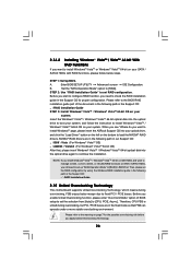
... a "Mediashield" shortcut on Start → Programs → NVIDIA Corporation → Mediashield → Mediashield. (There is built in NVIDIA ALL in one driver provided in our support CD. After you finish the driver installation, you install. 2.1 NVIDIA Windows RAID Installation Guide for Windows 2000 / XP / XP 64-bit Users A. 2. NVIDIA Windows RAID...
... a "Mediashield" shortcut on Start → Programs → NVIDIA Corporation → Mediashield → Mediashield. (There is built in NVIDIA ALL in one driver provided in our support CD. After you finish the driver installation, you install. 2.1 NVIDIA Windows RAID Installation Guide for Windows 2000 / XP / XP 64-bit Users A. 2. NVIDIA Windows RAID...
RAID Installation Guide
Page 18
..., or rebuild any RAID array. NVRAIDMAN window indicates that the array is synchronizing. The synchronization process will start and it will be completed in our support CD. C.
..., or rebuild any RAID array. NVRAIDMAN window indicates that the array is synchronizing. The synchronization process will start and it will be completed in our support CD. C.

User Manual
Page 4
3.3.3 ACPI Configuration 33 3.3.4 IDE Configuration 34 3.3.5 PCIPnP Configuration 36 3.3.6 Floppy Configuration 37 3.3.7 Super IO Configuration 37 3.3.8 USB Configuration 38 3.4 Hardware Health Event Monitoring Screen 39 3.5 Boot Screen 40 3.5.1 Boot Settings Configuration 40 3.6 Security Screen 41 3.7 Exit Screen 42 4 . Software Support 43 4.1 Install Operating System 43 4.2 Support CD Information 43 4.2.1 Running Support CD 43 4.2.2 Drivers Menu 43 4.2.3 Utilities Menu 43 4.2.4 Contact Information 43 APPENDIX: AMD's Cool 'n' QuietTM Technology ...... 44 4
3.3.3 ACPI Configuration 33 3.3.4 IDE Configuration 34 3.3.5 PCIPnP Configuration 36 3.3.6 Floppy Configuration 37 3.3.7 Super IO Configuration 37 3.3.8 USB Configuration 38 3.4 Hardware Health Event Monitoring Screen 39 3.5 Boot Screen 40 3.5.1 Boot Settings Configuration 40 3.6 Security Screen 41 3.7 Exit Screen 42 4 . Software Support 43 4.1 Install Operating System 43 4.2 Support CD Information 43 4.2.1 Running Support CD 43 4.2.2 Drivers Menu 43 4.2.3 Utilities Menu 43 4.2.4 Contact Information 43 APPENDIX: AMD's Cool 'n' QuietTM Technology ...... 44 4

User Manual
Page 5
... change without further notice. You may find the latest VGA cards and CPU support lists on ASRock website without notice. ASRock website http://www.asrock.com 1.1 Package Contents 1 x ASRock K8NF6G-VSTA Motherboard (Micro ATX Form Factor: 9.6-in x 8.2-in, 24.4 cm x 20.8 cm) 1 x ASRock K8NF6G-VSTA Quick Installation Guide 1 x ASRock K8NF6G-VSTA Support CD 1 x Ultra ATA 66/100/133 IDE Ribbon Cable (80-conductor) 1 x 3.5-in...
... change without further notice. You may find the latest VGA cards and CPU support lists on ASRock website without notice. ASRock website http://www.asrock.com 1.1 Package Contents 1 x ASRock K8NF6G-VSTA Motherboard (Micro ATX Form Factor: 9.6-in x 8.2-in, 24.4 cm x 20.8 cm) 1 x ASRock K8NF6G-VSTA Quick Installation Guide 1 x ASRock K8NF6G-VSTA Support CD 1 x Ultra ATA 66/100/133 IDE Ribbon Cable (80-conductor) 1 x 3.5-in...
User Manual
Page 6
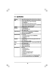
... Audio LAN Rear Panel I /O - 1 x PS/2 Mouse Port - 1 x PS/2 Keyboard Port - 1 x VGA Port - 1 x Parallel Port (ECP/EPP Support) - 4 x Ready-to FSB 1000 MHz (2.0 GT/s) - Socket 754 for AMD AthlonTM 64 and Sempron Processors - Max. capacity: 2GB - ASRock U-COP (see CAUTION 6) 6 Boot Failure Guard (B.F.G.) - 2 x PCI slots - 1 x PCI Express Graphics slot (see CAUTION 1) - Max. Pixel...
... Audio LAN Rear Panel I /O - 1 x PS/2 Mouse Port - 1 x PS/2 Keyboard Port - 1 x VGA Port - 1 x Parallel Port (ECP/EPP Support) - 4 x Ready-to FSB 1000 MHz (2.0 GT/s) - Socket 754 for AMD AthlonTM 64 and Sempron Processors - Max. capacity: 2GB - ASRock U-COP (see CAUTION 6) 6 Boot Failure Guard (B.F.G.) - 2 x PCI slots - 1 x PCI Express Graphics slot (see CAUTION 1) - Max. Pixel...
User Manual
Page 7
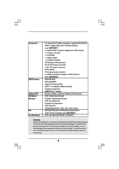
...; 2000/XP/XP 64-bit/VistaTM/ VistaTM 64-bit compliant (see CAUTION 8) - 4Mb AMI BIOS - Front panel audio connector - 2 x USB 2.0 headers (support 4 USB 2.0 ports) (see CAUTION 9) - CPU Temperature Sensing - Chassis Temperature Sensing - Overclocking may affect your system stability, or even cause damage to the components... and devices of your own risk and expense. AMI Legal BIOS - Supports "Plug and Play" - CPU Quiet Fan - Voltage Monitoring: +12V, +5V, +3.3V, Vcore - It should be done at your system. Connector...
...; 2000/XP/XP 64-bit/VistaTM/ VistaTM 64-bit compliant (see CAUTION 8) - 4Mb AMI BIOS - Front panel audio connector - 2 x USB 2.0 headers (support 4 USB 2.0 ports) (see CAUTION 9) - CPU Temperature Sensing - Chassis Temperature Sensing - Overclocking may affect your system stability, or even cause damage to the components... and devices of your own risk and expense. AMI Legal BIOS - Supports "Plug and Play" - CPU Quiet Fan - Voltage Monitoring: +12V, +5V, +3.3V, Vcore - It should be done at your system. Connector...
User Manual
Page 8
... update it is not recommended to SATAII mode. Before you install the PC system. 5. For audio output, this motherboard supports both stereo and mono modes. Microsoft® Windows® VistaTM / VistaTM 64-bit driver keeps on page 26 for ...read "Untied Overclocking Technology" on updating now. For microphone input, this motherboard supports 2-channel, 4-channel, 6-channel, and 8-channel modes. This motherboard supports Untied Overclocking Technology. ASRock website http://www.asrock.com 8 Although this motherboard offers stepless control, it back again. You can ...
... update it is not recommended to SATAII mode. Before you install the PC system. 5. For audio output, this motherboard supports both stereo and mono modes. Microsoft® Windows® VistaTM / VistaTM 64-bit driver keeps on page 26 for ...read "Untied Overclocking Technology" on updating now. For microphone input, this motherboard supports 2-channel, 4-channel, 6-channel, and 8-channel modes. This motherboard supports Untied Overclocking Technology. ASRock website http://www.asrock.com 8 Although this motherboard offers stepless control, it back again. You can ...

User Manual
Page 15
... slot or HDMR slot to use. Step 5. PCIE2 (PCIE x1 slot) is completely seated on K8NF6G-VSTA motherboard. Before installing the expansion card, please make necessary hardware settings for PCI Express cards with v.... slot is used for later use . you intend to use . PCIE1 (PCI Express Graphics slot) supports most of the expansion card and make sure that the power supply is switched off or the power ...32-bit PCI interface. PCIE Slots: PCIE1 (PCI Express Graphics slot) is used to insert an ASRock HDMR card with x1 lane width cards, such as ATiTM X300, X550, X700, and X800 series ...
... slot or HDMR slot to use. Step 5. PCIE2 (PCIE x1 slot) is completely seated on K8NF6G-VSTA motherboard. Before installing the expansion card, please make necessary hardware settings for PCI Express cards with v.... slot is used for later use . you intend to use . PCIE1 (PCI Express Graphics slot) supports most of the expansion card and make sure that the power supply is switched off or the power ...32-bit PCI interface. PCIE Slots: PCIE1 (PCI Express Graphics slot) is used to insert an ASRock HDMR card with x1 lane width cards, such as ATiTM X300, X550, X700, and X800 series ...

User Manual
Page 16
.... Install the onboard VGA driver to install it again. 5. Right-click the display icon and select "Attached", if necessary. 2.5 Easy Multi Monitor Feature This motherboard supports Multi Monitor upgrade. Boot your system. If you select is no need to your system. C. Right-click the display icon in this monitor". Select the...
.... Install the onboard VGA driver to install it again. 5. Right-click the display icon and select "Attached", if necessary. 2.5 Easy Multi Monitor Feature This motherboard supports Multi Monitor upgrade. Boot your system. If you select is no need to your system. C. Right-click the display icon in this monitor". Select the...

User Manual
Page 18
... your IDE device vendor for internal storage devices. Primary IDE connector (Blue) (39-pin IDE1, see p.10, No. 5) SATAII_2 SATAII_1 These Serial ATAII (SATAII) connectors support SATAII or SATA hard disk for the details. Serial ATA (SATA) Power Cable (Optional) connect to the SATA HDD power connector connect to the power...
... your IDE device vendor for internal storage devices. Primary IDE connector (Blue) (39-pin IDE1, see p.10, No. 5) SATAII_2 SATAII_1 These Serial ATAII (SATAII) connectors support SATAII or SATA hard disk for the details. Serial ATA (SATA) Power Cable (Optional) connect to the SATA HDD power connector connect to the power...

User Manual
Page 19
This connector allows you use AC'97 audio panel, please install it to [Enabled]. 19 High Definition Audio supports Jack Sensing, but the panel wire on the chassis must support HDA to MIC2_L. MIC_RET and OUT_RET are two USB 2.0 headers on the I/O panel, there are for ...OUT2_R MIC2_R MIC2_L This is an interface for HD audio panel only. B. You don't need to OUT2_L. Each USB 2.0 header can support two USB 2.0 ports. This header supports an optional wireless transmitting and receiving infrared module. C. Set the Front Panel Control option from sound sources such as below: A.
This connector allows you use AC'97 audio panel, please install it to [Enabled]. 19 High Definition Audio supports Jack Sensing, but the panel wire on the chassis must support HDA to MIC2_L. MIC_RET and OUT_RET are two USB 2.0 headers on the I/O panel, there are for ...OUT2_R MIC2_R MIC2_L This is an interface for HD audio panel only. B. You don't need to OUT2_L. Each USB 2.0 header can support two USB 2.0 ports. This header supports an optional wireless transmitting and receiving infrared module. C. Set the Front Panel Control option from sound sources such as below: A.

User Manual
Page 20
... 1) (see p.10 No. 13) Chassis Fan Connector (3-pin CHA_FAN1) (see p.10 No. 8) Please note that it to this motherboard provides 4-Pin CPU fan (Quiet Fan) support, the 3-Pin CPU fan still can work successfully even without the fan speed control function. Failing to the ground pin. Enter Windows system. F.
... 1) (see p.10 No. 13) Chassis Fan Connector (3-pin CHA_FAN1) (see p.10 No. 8) Please note that it to this motherboard provides 4-Pin CPU fan (Quiet Fan) support, the 3-Pin CPU fan still can work successfully even without the fan speed control function. Failing to the ground pin. Enter Windows system. F.

User Manual
Page 21
RRXD1 DDTR#1 DDSR#1 CCTS#1 1 RRI#1 RRTS#1 GND TTXD1 DDCD#1 This COM1 header supports a serial port module. 21 Game Port Header (15-pin GAME1) (see p.10 No. 17) Serial port Header (9-pin COM1) (see p.10 No.26) +5V JBB1 JBX MIDI_OUT JBY JBB2 MIDI_IN 1 +5V JAB2 JAY GND GND JAX JAB1 +5V Connect a Game cable to this header if the Game port bracket is installed.
RRXD1 DDTR#1 DDSR#1 CCTS#1 1 RRI#1 RRTS#1 GND TTXD1 DDCD#1 This COM1 header supports a serial port module. 21 Game Port Header (15-pin GAME1) (see p.10 No. 17) Serial port Header (9-pin COM1) (see p.10 No.26) +5V JBB1 JBX MIDI_OUT JBY JBB2 MIDI_IN 1 +5V JAB2 JAY GND GND JAX JAB1 +5V Connect a Game cable to this header if the Game port bracket is installed.

User Manual
Page 22
... hard disk to your computer, please carefully read below instruction with the best performance. Please visit HITACHI's website for details: http://www.hitachigst.com/hdd/support/download.htm The above examples are just for the updates. 22 HITACHI Please use the Feature Tool, a DOS-bootable tool, for changing various ATA features...
... hard disk to your computer, please carefully read below instruction with the best performance. Please visit HITACHI's website for details: http://www.hitachigst.com/hdd/support/download.htm The above examples are just for the updates. 22 HITACHI Please use the Feature Tool, a DOS-bootable tool, for changing various ATA features...

User Manual
Page 23
...your optical drive first. STEP 4: Connect the other end of the SATA data cable to install the SATA / SATAII hard disks. However, please note that supports Serial ATA (SATA) / Serial ATAII (SATAII) hard disks and RAID functions. 2.9 Serial ATA (SATA) / Serial ATAII (SATAII) Hard Disks Installation This...Therefore, the drivers you to the SATA / SATAII hard disk. 2.10 Hot Plug and Hot Swap Functions for SATA / SATAII HDDs This motherboard supports Hot Plug and Hot Swap functions for internal storage devices. STEP 1: Install the SATA / SATAII hard disks into the SATA / SATAII HDD. This...
...your optical drive first. STEP 4: Connect the other end of the SATA data cable to install the SATA / SATAII hard disks. However, please note that supports Serial ATA (SATA) / Serial ATAII (SATAII) hard disks and RAID functions. 2.9 Serial ATA (SATA) / Serial ATAII (SATAII) Hard Disks Installation This...Therefore, the drivers you to the SATA / SATAII hard disk. 2.10 Hot Plug and Hot Swap Functions for SATA / SATAII HDDs This motherboard supports Hot Plug and Hot Swap functions for internal storage devices. STEP 1: Install the SATA / SATAII hard disks into the SATA / SATAII HDD. This...

User Manual
Page 24
... related information in the future, you plan to use HDMR card function on this motherboard, please follow below then. 1. Install HDMR card driver from our support CD to your SATA / SATAII HDDs without RAID functions, you don't have to make sure that the HDMR card is supposed to include SP4. Please...
... related information in the future, you plan to use HDMR card function on this motherboard, please follow below then. 1. Install HDMR card driver from our support CD to your SATA / SATAII HDDs without RAID functions, you don't have to make sure that the HDMR card is supposed to include SP4. Please...

User Manual
Page 25
... diskette [YN]?", press . STEP 1: Make a SATA / SATAII Driver Diskette. When you still need to check the RAID installation guide in the Support CD for boot devices selection appears. E. STEP 2: Set Up BIOS. When prompted, insert the SATA / SATAII driver diskette containing the NVIDIA®... RAID driver. Insert the ASRock Support CD into the floppy drive, and press any key. At the beginning of system boot-up "SATA Operation Mode" to [RAID] in BIOS...
... diskette [YN]?", press . STEP 1: Make a SATA / SATAII Driver Diskette. When you still need to check the RAID installation guide in the Support CD for boot devices selection appears. E. STEP 2: Set Up BIOS. When prompted, insert the SATA / SATAII driver diskette containing the NVIDIA®... RAID driver. Insert the ASRock Support CD into the floppy drive, and press any key. At the beginning of system boot-up "SATA Operation Mode" to [RAID] in BIOS...
User Manual
Page 26
... want to manage (create, convert, delete, or rebuild) RAID functions on SATA / SATAII HDDs, you still need to check the RAID installation guide in our Support CD: .. \ I386 \ Vista (For Windows® VistaTM OS) .. \ AMD64 \ Vista64 (For Windows® VistaTM 64-bit OS) After that FSB can operate under a more stable...-bit OS on your optical drive, and click the "Load Driver" button on the left on the bottom to install Windows?" B. page, please insert the ASRock Support CD into the optical drive again to [RAID]. Enter BIOS SETUP UTILITY Advanced screen IDE Configuration.
... want to manage (create, convert, delete, or rebuild) RAID functions on SATA / SATAII HDDs, you still need to check the RAID installation guide in our Support CD: .. \ I386 \ Vista (For Windows® VistaTM OS) .. \ AMD64 \ Vista64 (For Windows® VistaTM 64-bit OS) After that FSB can operate under a more stable...-bit OS on your optical drive, and click the "Load Driver" button on the left on the bottom to install Windows?" B. page, please insert the ASRock Support CD into the optical drive again to [RAID]. Enter BIOS SETUP UTILITY Advanced screen IDE Configuration.


