
User Manual
Page 3
...BIOS Setup 17 3.1 BIOS Setup Utility 17 3.1.1 BIOS Menu Bar 17 3.1.2 Legend Bar 18 3.2 Main Menu 18 3.3 Advanced, Security, Power, Boot, and Exit Menus 20 4. Power Setup Menu 28 4. Software Support 21 4.1 Install Operating System 21 4.2 Support CD Information 21 4.2.1 Running Support CD 21 4.2.2 Drivers Menu 21 4.2.3 Utilities Menu 21 4.2.4 ASRock... 2.5 Jumpers Setup 13 2.6 Onboard Headers and Connectors 15 3. Exit Menu 30 3 Advanced BIOS Setup Menu 22 2. Security Setup Menu 27 3. Introduction 4 1.1 Package Contents 4 1.2 Specifications 5 1.3 Motherboard Layout...
...BIOS Setup 17 3.1 BIOS Setup Utility 17 3.1.1 BIOS Menu Bar 17 3.1.2 Legend Bar 18 3.2 Main Menu 18 3.3 Advanced, Security, Power, Boot, and Exit Menus 20 4. Power Setup Menu 28 4. Software Support 21 4.1 Install Operating System 21 4.2 Support CD Information 21 4.2.1 Running Support CD 21 4.2.2 Drivers Menu 21 4.2.3 Utilities Menu 21 4.2.4 ASRock... 2.5 Jumpers Setup 13 2.6 Onboard Headers and Connectors 15 3. Exit Menu 30 3 Advanced BIOS Setup Menu 22 2. Security Setup Menu 27 3. Introduction 4 1.1 Package Contents 4 1.2 Specifications 5 1.3 Motherboard Layout...

User Manual
Page 4
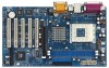
...: 12.0-in x 7.0-in, 30.5 cm x 17.8 cm) 1 x ASRock K7VT4A+ Quick Installation Guide 1 x ASRock K7VT4A+ Support CD 1 x Ultra ATA 66/100/133 IDE Ribbon Cable (80-conductor) 1 x 3.5-in Appendix on page 22 for purchasing ASRock K7VT4A+ motherboard, a reliable motherboard produced under ASRock's consistently stringent quality control. Chapter 3 and 4 contain basic BIOS setup and support CD information. Because the motherboard...
...: 12.0-in x 7.0-in, 30.5 cm x 17.8 cm) 1 x ASRock K7VT4A+ Quick Installation Guide 1 x ASRock K7VT4A+ Support CD 1 x Ultra ATA 66/100/133 IDE Ribbon Cable (80-conductor) 1 x 3.5-in Appendix on page 22 for purchasing ASRock K7VT4A+ motherboard, a reliable motherboard produced under ASRock's consistently stringent quality control. Chapter 3 and 4 contain basic BIOS setup and support CD information. Because the motherboard...
User Manual
Page 5
... (10/100 Ethernet), supports Wake-On-LAN Hardware Monitor: CPU temperature sensing Motherboard temperature sensing CPU overheat shutdown to protect CPU life (ASRock U-COP)(see CAUTION 1) CPU fan tachometer Chassis fan tachometer Voltage monitoring: +12V, +5V, +3.3V, Vcore PCI slots: 5 slots...: ECP/EPP support, 1 RJ-45 port, 4 default USB 2.0 ports, Audio Jack: Line Out / Line In / Microphone + Game port BIOS: AMI legal BIOS, Supports "Plug and Play", ACPI 1.1 compliance wake up events, SMBIOS 2.3.1 support, CPU frequency stepless control (only for advanced users' reference, see...
... (10/100 Ethernet), supports Wake-On-LAN Hardware Monitor: CPU temperature sensing Motherboard temperature sensing CPU overheat shutdown to protect CPU life (ASRock U-COP)(see CAUTION 1) CPU fan tachometer Chassis fan tachometer Voltage monitoring: +12V, +5V, +3.3V, Vcore PCI slots: 5 slots...: ECP/EPP support, 1 RJ-45 port, 4 default USB 2.0 ports, Audio Jack: Line Out / Line In / Microphone + Game port BIOS: AMI legal BIOS, Supports "Plug and Play", ACPI 1.1 compliance wake up events, SMBIOS 2.3.1 support, CPU frequency stepless control (only for advanced users' reference, see...

User Manual
Page 6
Do NOT use the "Manual" option as the FSB setting in BIOS setup to perform over clocking. You must set the FSB jumper according to your AMD CPU before you use a 3.3V AGP card on the motherboard ...
Do NOT use the "Manual" option as the FSB setting in BIOS setup to perform over clocking. You must set the FSB jumper according to your AMD CPU before you use a 3.3V AGP card on the motherboard ...
User Manual
Page 7
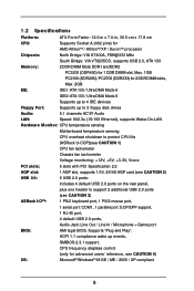
... OUT VIA Line LIINnE IN KT400A AUX1 CHIPSET MMInICicIN 7 24 CD1 8 JR1 23 JL1 1 AUDIO1 AGP 8X K7VT4A+ 22 1.5V_AGP1 9 AUDIO CODEC LAN PHY SUPER I/O DDR400 PCI1 PCI2 1 FSB_SEL0 1 FSB_SEL1 1 FSB_SEL2 10 21 20 2MB BIOS PCI3 USB2.0 5.1CH PCI4 11 VIA VT8235 12 CHA_FAN1 CMOS ATA133 BATTERY FSB333 13 1 CLRCMOS2 1 IR1...
... OUT VIA Line LIINnE IN KT400A AUX1 CHIPSET MMInICicIN 7 24 CD1 8 JR1 23 JL1 1 AUDIO1 AGP 8X K7VT4A+ 22 1.5V_AGP1 9 AUDIO CODEC LAN PHY SUPER I/O DDR400 PCI1 PCI2 1 FSB_SEL0 1 FSB_SEL1 1 FSB_SEL2 10 21 20 2MB BIOS PCI3 USB2.0 5.1CH PCI4 11 VIA VT8235 12 CHA_FAN1 CMOS ATA133 BATTERY FSB333 13 1 CLRCMOS2 1 IR1...

User Manual
Page 13
... shut it requires 2 Amp and higher standby current provided by jumper-setting. If you need to clear the CMOS when you just finish updating the BIOS, you do not clear the CMOS right after you to enable (see p.7 item 10) Setting 1_2 FSB_SEL0 OPEN FSB_SEL1 1_2 FSB_SEL2 FSB 200MHz OPEN FSB_SEL0... 333MHz Note: The CPU FSB frequency of your AMD CPU. JR1 / JL1 Jumpers JR1 (see p.7 item 19) 2-pin jumper Note: CLRCMOS2 allows you update the BIOS. The data in CMOS. If no jumper cap is placed on the pins, the jumper is placed on pins, the jumper is determined by power...
... shut it requires 2 Amp and higher standby current provided by jumper-setting. If you need to clear the CMOS when you just finish updating the BIOS, you do not clear the CMOS right after you to enable (see p.7 item 10) Setting 1_2 FSB_SEL0 OPEN FSB_SEL1 1_2 FSB_SEL2 FSB 200MHz OPEN FSB_SEL0... 333MHz Note: The CPU FSB frequency of your AMD CPU. JR1 / JL1 Jumpers JR1 (see p.7 item 19) 2-pin jumper Note: CLRCMOS2 allows you update the BIOS. The data in CMOS. If no jumper cap is placed on the pins, the jumper is placed on pins, the jumper is determined by power...

User Manual
Page 17
... by pressing + + , or by turning the system off and then back on the system chassis. BIOS Setup 3.1 BIOS Setup Utility This section explains how to use the BIOS Setup Utility to configure your screen. 3.1.1 BIOS Menu Bar The top of the Setup Screen is a menu-driven program, which allows you wish to... on the keyboard until the desired item is highlighted. 3.1.2 Legend Bar At the bottom of the screen has a menu bar with the following BIOS setup screens and descriptions are for reference purpose only, and may also restart the system by pressing the reset button on . Because the...
... by pressing + + , or by turning the system off and then back on the system chassis. BIOS Setup 3.1 BIOS Setup Utility This section explains how to use the BIOS Setup Utility to configure your screen. 3.1.1 BIOS Menu Bar The top of the Setup Screen is a menu-driven program, which allows you wish to... on the keyboard until the desired item is highlighted. 3.1.2 Legend Bar At the bottom of the screen has a menu bar with the following BIOS setup screens and descriptions are for reference purpose only, and may also restart the system by pressing the reset button on . Because the...

User Manual
Page 18
... Increases or decreases values Brings up to 2099). Dec Day: 01 - 31 Year: 1980 - 2099 K7VT4A+ BIOS P1.00 AMD Athlon(tm) XP 2600+ 2133 MHz 128 KB 256 KB 512 MB 512 MB /...the Month, Day, and Year fields. Main Advanced System Date System Time Floppy Drives IDE Devices BIOS Version Processor Type Processor Speed L1 Cache Size L2 Cache Size Total Memory DDR1 DDR2 AMIBIOS SETUP UTILITY...] Set the system to configure IDE devices. 18 Floppy Drives Use this to the time that you enter the BIOS Setup Utility, the following screen appears. Valid values for month, day, and year are Month: (Jan to ...
... Increases or decreases values Brings up to 2099). Dec Day: 01 - 31 Year: 1980 - 2099 K7VT4A+ BIOS P1.00 AMD Athlon(tm) XP 2600+ 2133 MHz 128 KB 256 KB 512 MB 512 MB /...the Month, Day, and Year fields. Main Advanced System Date System Time Floppy Drives IDE Devices BIOS Version Processor Type Processor Speed L1 Cache Size L2 Cache Size Total Memory DDR1 DDR2 AMIBIOS SETUP UTILITY...] Set the system to configure IDE devices. 18 Floppy Drives Use this to the time that you enter the BIOS Setup Utility, the following screen appears. Valid values for month, day, and year are Month: (Jan to ...

User Manual
Page 19
... too old or too new. If the hard disk was already formatted on this sub-menu. Please make sure you can write the data into BIOS, use a disk utility, such as FDISK, to that you have the correct configuration information supplied by the drive manufacturer. Before attempting to configure a ... device, first, please select "IDE Devices" on Main menu and press to manually enter the IDE hard disk drive parameters. This is successful, the BIOS Setup automatically fills in the correct values for the drive. TYPE To set the type of cylinders, heads, and sectors per track for the remaining...
... too old or too new. If the hard disk was already formatted on this sub-menu. Please make sure you can write the data into BIOS, use a disk utility, such as FDISK, to that you have the correct configuration information supplied by the drive manufacturer. Before attempting to configure a ... device, first, please select "IDE Devices" on Main menu and press to manually enter the IDE hard disk drive parameters. This is successful, the BIOS Setup automatically fills in the correct values for the drive. TYPE To set the type of cylinders, heads, and sectors per track for the remaining...

User Manual
Page 20
... listed in the Appendix. Sectors This is used to select the LBA mode for IDE ARMD (ATAPI Removable Media Device), such as calculated by the BIOS based on the drive information you entered.
... listed in the Appendix. Sectors This is used to select the LBA mode for IDE ARMD (ATAPI Removable Media Device), such as calculated by the BIOS based on the drive information you entered.

User Manual
Page 22
... (DDR400)]. This is determined by the jumper-setting. [Manual] This allows user to set to [Auto], the motherboard will introduce you the following BIOS Setup menus: "Advanced," "Security," "Power," "Boot," and "Exit." 1. It will let the CPU host frequency of this option is set the... unless you must set to perform over clocking. Wrong setup may select other value as the FSB setting in BIOS setup to [Enabled]. 22 Advanced BIOS Setup Menu Main Advanced AMIBIOS SETUP UTILITY - You may cause problems during operation. Flexibility Option The default value of...
... (DDR400)]. This is determined by the jumper-setting. [Manual] This allows user to set to [Auto], the motherboard will introduce you the following BIOS Setup menus: "Advanced," "Security," "Power," "Boot," and "Exit." 1. It will let the CPU host frequency of this option is set the... unless you must set to perform over clocking. Wrong setup may select other value as the FSB setting in BIOS setup to [Enabled]. 22 Advanced BIOS Setup Menu Main Advanced AMIBIOS SETUP UTILITY - You may cause problems during operation. Flexibility Option The default value of...

User Manual
Page 27
Configuration options: [Setup], [Always]. If [Always] option is selected, the "Password Check" is performed before both boot-up and BIOS setup. 27 Password Check Setup F1:Help Esc:Exit :Select Item :Select Menu +/-:Change Values Enter:Select Sub-Menu F9:Setup Defaults F10:Save & Exit ... a 1 to set the supervisor password. Valid password can be a 1 to set the Supervisor Password. If [Setup] option is selected, the "Password Check" is performed before BIOS setup. Set Supervisor Password: Press to 6 alphanumeric characters combination. 2.
Configuration options: [Setup], [Always]. If [Always] option is selected, the "Password Check" is performed before both boot-up and BIOS setup. 27 Password Check Setup F1:Help Esc:Exit :Select Item :Select Menu +/-:Change Values Enter:Select Sub-Menu F9:Setup Defaults F10:Save & Exit ... a 1 to set the supervisor password. Valid password can be a 1 to set the Supervisor Password. If [Setup] option is selected, the "Password Check" is performed before BIOS setup. Set Supervisor Password: Press to 6 alphanumeric characters combination. 2.

User Manual
Page 30
...message "Load setup original values" will appear. Exit Discarding Changes After you press , original values will save the current settings and exit the BIOS SETUP Utility. If you press , you press , it will be restored and all the setup configuration. Discard Changes After you press , ... Default Settings After you enter the sub-menu, the message "Save current settings and exit" will appear. If you will exit the BIOS Setup Utility without saving changes" will appear. VERSION 3.31a Security Power Boot Exit Exit Saving Changes Exit Discarding Changes Load Default Settings Discard...
...message "Load setup original values" will appear. Exit Discarding Changes After you press , original values will save the current settings and exit the BIOS SETUP Utility. If you press , you press , it will be restored and all the setup configuration. Discard Changes After you press , ... Default Settings After you enter the sub-menu, the message "Save current settings and exit" will appear. If you will exit the BIOS Setup Utility without saving changes" will appear. VERSION 3.31a Security Power Boot Exit Exit Saving Changes Exit Discarding Changes Load Default Settings Discard...

User Manual
Page 3
... 4 1.1 Package Contents 4 1.2 Specifications 5 1.3 Motherboard Layout 7 1.4 ASRock I/OTM 8 2 Installation 9 2.1 Screw Holes 9 2.2 Pre-installation Precautions 9 2.3 CPU Installation 10 2.4 Installation of CPU Fan and Heatsink 10 2.5 Installation of Memory Modules (DIMM 11 2.6 Expansion Slots (PCI and AGP Slots 12 2.7 Jumpers Setup 13 2.8 Connectors 15 3 BIOS Setup 17 3.1 BIOS Setup Utility 17 3.1.1 BIOS Menu Bar 17 3.1.2 Legend Bar...
... 4 1.1 Package Contents 4 1.2 Specifications 5 1.3 Motherboard Layout 7 1.4 ASRock I/OTM 8 2 Installation 9 2.1 Screw Holes 9 2.2 Pre-installation Precautions 9 2.3 CPU Installation 10 2.4 Installation of CPU Fan and Heatsink 10 2.5 Installation of Memory Modules (DIMM 11 2.6 Expansion Slots (PCI and AGP Slots 12 2.7 Jumpers Setup 13 2.8 Connectors 15 3 BIOS Setup 17 3.1 BIOS Setup Utility 17 3.1.1 BIOS Menu Bar 17 3.1.2 Legend Bar...

User Manual
Page 4
Chapter 1 and 2 of this manual will be available on ASRock website as well. Chapter 3 and 4 contain basic BIOS setup and support CD information. You may find the latest memory and CPU support lists on ASRock website without notice. ASRock website http://www.asrock.com 1.1 Package Contents ASRock K7VT4A Motherboard (ATX Form Factor: 12.0-in x 7.0-in Floppy Drive One...
Chapter 1 and 2 of this manual will be available on ASRock website as well. Chapter 3 and 4 contain basic BIOS setup and support CD information. You may find the latest memory and CPU support lists on ASRock website without notice. ASRock website http://www.asrock.com 1.1 Package Contents ASRock K7VT4A Motherboard (ATX Form Factor: 12.0-in x 7.0-in Floppy Drive One...

User Manual
Page 5
... (see CAUTION 2) USB 2.0: 6 USB 2.0 ports: includes 4 default USB 2.0 ports on the rear panel, plus one header to support 2 additional USB 2.0 ports ASRock I/OTM: (see CAUTION 3) 1 PS/2 keyboard port, 1 PS/2 mouse port, 1 serial port: COM1, 1 parallel port: ECP/EPP support, 1 RJ 45 port..., 4 default USB 2.0 ports, Audio Jack: Line Out / Line In / Microphone + Game port BIOS: AMI legal BIOS, Supports "Plug and Play", ACPI 1.1 compliance wake up events, SMBIOS 2.3.1 support, CPU frequency stepless control (only for advanced users' reference, see ...
... (see CAUTION 2) USB 2.0: 6 USB 2.0 ports: includes 4 default USB 2.0 ports on the rear panel, plus one header to support 2 additional USB 2.0 ports ASRock I/OTM: (see CAUTION 3) 1 PS/2 keyboard port, 1 PS/2 mouse port, 1 serial port: COM1, 1 parallel port: ECP/EPP support, 1 RJ 45 port..., 4 default USB 2.0 ports, Audio Jack: Line Out / Line In / Microphone + Game port BIOS: AMI legal BIOS, Supports "Plug and Play", ACPI 1.1 compliance wake up events, SMBIOS 2.3.1 support, CPU frequency stepless control (only for advanced users' reference, see ...

User Manual
Page 6
... Management for details. 6 Do NOT use a 3.3V AGP card on the motherboard functions properly before you use the "Manual" option as the FSB setting in BIOS setup to spray thermal grease between the CPU and the heatsink when you resume the system. It may not work properly under Microsoft® Windows...
... Management for details. 6 Do NOT use a 3.3V AGP card on the motherboard functions properly before you use the "Manual" option as the FSB setting in BIOS setup to spray thermal grease between the CPU and the heatsink when you resume the system. It may not work properly under Microsoft® Windows...

User Manual
Page 7
... AAUUDDIIOO11 LiLInnineein MMInicicin AUX1 VIA KT400A Chipset 27 CD1 JR1 26 25 JL1 1 AUDIO1 24 DDR400 AGP 8X K7VT4A AGP1 23 LAN PHY 22 AUDIO CODEC PCI 1 Super I/O PCI 2 7 8 9 FSB_SEL0 1 10 21 20 2MB BIOS CMOS Battery PCI 3 USB2.0 5.1CH PCI 4 ATA133 FSB333 11 VIA VT8235 12 CHA_FAN1 13 1 CLRCMOS2 PCI 5 FLOPPY1...
... AAUUDDIIOO11 LiLInnineein MMInicicin AUX1 VIA KT400A Chipset 27 CD1 JR1 26 25 JL1 1 AUDIO1 24 DDR400 AGP 8X K7VT4A AGP1 23 LAN PHY 22 AUDIO CODEC PCI 1 Super I/O PCI 2 7 8 9 FSB_SEL0 1 10 21 20 2MB BIOS CMOS Battery PCI 3 USB2.0 5.1CH PCI 4 ATA133 FSB333 11 VIA VT8235 12 CHA_FAN1 13 1 CLRCMOS2 PCI 5 FLOPPY1...

User Manual
Page 13
... unplug the power cord, then use the "Manual" option as system password, date, time, and system setup parameters. Please remember to clear the data in BIOS setup to short the pins on CLRCMOS2 for PS/2 or USB wake up the system first, and then shut it requires 2 Amp and higher standby... shows a 3-pin jumper whose pin1 and pin2 are setup. PS2_USB_PWR1 1_2 2_3 Short pin2, pin3 to clear the CMOS when you just finish updating the BIOS, you need to enable (see p.7 item 19) 2-pin jumper Note: CLRCMOS2 allows you use a jumper cap to perform over clocking.
... unplug the power cord, then use the "Manual" option as system password, date, time, and system setup parameters. Please remember to clear the data in BIOS setup to short the pins on CLRCMOS2 for PS/2 or USB wake up the system first, and then shut it requires 2 Amp and higher standby... shows a 3-pin jumper whose pin1 and pin2 are setup. PS2_USB_PWR1 1_2 2_3 Short pin2, pin3 to clear the CMOS when you just finish updating the BIOS, you need to enable (see p.7 item 19) 2-pin jumper Note: CLRCMOS2 allows you use a jumper cap to perform over clocking.

User Manual
Page 17
...The following selections: MAIN Sets up the basic system configuration ADVANCED Sets up the advanced features SECURITY Sets up the computer. You may run the BIOS Setup when you wish to be user-friendly. Please press during the PowerOn-Self-Test (POST) to locate and load the Operating System EXIT ...Exits the current menu or the BIOS Setup To access the menu bar items, press the right or left arrow key on the system chassis. It is constantly being updated, the ...
...The following selections: MAIN Sets up the basic system configuration ADVANCED Sets up the advanced features SECURITY Sets up the computer. You may run the BIOS Setup when you wish to be user-friendly. Please press during the PowerOn-Self-Test (POST) to locate and load the Operating System EXIT ...Exits the current menu or the BIOS Setup To access the menu bar items, press the right or left arrow key on the system chassis. It is constantly being updated, the ...


