
User Manual
Page 3
... Menu 28 4. Software Support 21 4.1 Install Operating System 21 4.2 Support CD Information 21 4.2.1 Running Support CD 21 4.2.2 Drivers Menu 21 4.2.3 Utilities Menu 21 4.2.4 ASRock "PC-DIY Live Demo" Program 21 4.2.5 Contact Information 21 Appendix 22 1. Boot Setup Menu 29 5. Exit Menu 30 3 Security Setup Menu 27 3. BIOS Setup ... BIOS Menu Bar 17 3.1.2 Legend Bar 18 3.2 Main Menu 18 3.3 Advanced, Security, Power, Boot, and Exit Menus 20 4. Contents 1. Introduction 4 1.1 Package Contents 4 1.2 Specifications 5 1.3 Motherboard Layout 7 1.4 ASRock I/O 8 TM ...2.
... Menu 28 4. Software Support 21 4.1 Install Operating System 21 4.2 Support CD Information 21 4.2.1 Running Support CD 21 4.2.2 Drivers Menu 21 4.2.3 Utilities Menu 21 4.2.4 ASRock "PC-DIY Live Demo" Program 21 4.2.5 Contact Information 21 Appendix 22 1. Boot Setup Menu 29 5. Exit Menu 30 3 Security Setup Menu 27 3. BIOS Setup ... BIOS Menu Bar 17 3.1.2 Legend Bar 18 3.2 Main Menu 18 3.3 Advanced, Security, Power, Boot, and Exit Menus 20 4. Contents 1. Introduction 4 1.1 Package Contents 4 1.2 Specifications 5 1.3 Motherboard Layout 7 1.4 ASRock I/O 8 TM ...2.

User Manual
Page 4
... updated, the content of advanced BIOS setup can be found in Floppy Drive Ribbon Cable 1 x ASRock I/OTM Shield 4 ASRock website http://www.asrock.com 1.1 Package Contents 1 x ASRock K7VT4A+ Motherboard (ATX Form Factor: 12.0-in x 7.0-in, 30.5 cm x 17.8 cm) 1 x ASRock K7VT4A+ Quick Installation Guide 1 x ASRock K7VT4A+ Support CD 1 x Ultra ATA 66/100/133 IDE Ribbon Cable (80-conductor) 1 x 3.5-in Appendix...
... updated, the content of advanced BIOS setup can be found in Floppy Drive Ribbon Cable 1 x ASRock I/OTM Shield 4 ASRock website http://www.asrock.com 1.1 Package Contents 1 x ASRock K7VT4A+ Motherboard (ATX Form Factor: 12.0-in x 7.0-in, 30.5 cm x 17.8 cm) 1 x ASRock K7VT4A+ Quick Installation Guide 1 x ASRock K7VT4A+ Support CD 1 x Ultra ATA 66/100/133 IDE Ribbon Cable (80-conductor) 1 x 3.5-in Appendix...
User Manual
Page 5
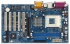
...Audio LAN: Speed: 802.3u (10/100 Ethernet), supports Wake-On-LAN Hardware Monitor: CPU temperature sensing Motherboard temperature sensing CPU overheat shutdown to protect CPU life (ASRock U-COP)(see CAUTION 1) CPU fan tachometer Chassis fan tachometer Voltage monitoring: +12V, +5V, +3.3V, Vcore... USB 2.0: 6 USB 2.0 ports: includes 4 default USB 2.0 ports on the rear panel, plus one header to support 2 additional USB 2.0 ports (see CAUTION 3) ASRock I/OTM: 1 PS/2 keyboard port, 1 PS/2 mouse port, 1 serial port: COM1, 1 parallel port: ECP/EPP support, 1 RJ-45 port, 4 default ...
...Audio LAN: Speed: 802.3u (10/100 Ethernet), supports Wake-On-LAN Hardware Monitor: CPU temperature sensing Motherboard temperature sensing CPU overheat shutdown to protect CPU life (ASRock U-COP)(see CAUTION 1) CPU fan tachometer Chassis fan tachometer Voltage monitoring: +12V, +5V, +3.3V, Vcore... USB 2.0: 6 USB 2.0 ports: includes 4 default USB 2.0 ports on the rear panel, plus one header to support 2 additional USB 2.0 ports (see CAUTION 3) ASRock I/OTM: 1 PS/2 keyboard port, 1 PS/2 mouse port, 1 serial port: COM1, 1 parallel port: ECP/EPP support, 1 RJ-45 port, 4 default ...

User Manual
Page 6
...system will automatically shutdown. Do NOT use the "Manual" option as the FSB setting in BIOS setup to perform over clocking. Although this motherboard! Please check page 22 for USB 2.0 works fine under Microsoft® Windows® 98/ME. You must set the FSB jumper according...174; Windows® XP SP1/2000 SP4. CAUTION! 1. Frequencies other than the recommended CPU bus frequencies may cause the instability of this motherboard offers stepless control, it back again. To improve heat dissipation, remember to Microsoft® official document at http://www.microsoft.com/whdc/...
...system will automatically shutdown. Do NOT use the "Manual" option as the FSB setting in BIOS setup to perform over clocking. Although this motherboard! Please check page 22 for USB 2.0 works fine under Microsoft® Windows® 98/ME. You must set the FSB jumper according...174; Windows® XP SP1/2000 SP4. CAUTION! 1. Frequencies other than the recommended CPU bus frequencies may cause the instability of this motherboard offers stepless control, it back again. To improve heat dissipation, remember to Microsoft® official document at http://www.microsoft.com/whdc/...
User Manual
Page 7
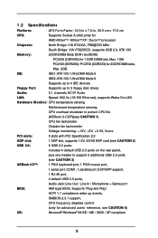
1.3 Motherboard Layout 1 2 34 5 6 17.8cm (7.0 in) PS/2 MOUSE PS/2 KEYBOARD SERIAL PORT (COM1) PS2_USB_PWR1 1 CPU_FAN1 FID4 1 FID3 1 FID2 1 FID1 1 FID0 1 J1 SOCKET 462 DDR 1 (64/72 ... IDE1 IDE2 USB 2.0 PORTS 25 GGAAMMEE_ AAUUDDIIOO11 LINE OUT VIA Line LIINnE IN KT400A AUX1 CHIPSET MMInICicIN 7 24 CD1 8 JR1 23 JL1 1 AUDIO1 AGP 8X K7VT4A+ 22 1.5V_AGP1 9 AUDIO CODEC LAN PHY SUPER I/O DDR400 PCI1 PCI2 1 FSB_SEL0 1 FSB_SEL1 1 FSB_SEL2 10 21 20 2MB BIOS PCI3 USB2.0 5.1CH PCI4 11 VIA VT8235...
1.3 Motherboard Layout 1 2 34 5 6 17.8cm (7.0 in) PS/2 MOUSE PS/2 KEYBOARD SERIAL PORT (COM1) PS2_USB_PWR1 1 CPU_FAN1 FID4 1 FID3 1 FID2 1 FID1 1 FID0 1 J1 SOCKET 462 DDR 1 (64/72 ... IDE1 IDE2 USB 2.0 PORTS 25 GGAAMMEE_ AAUUDDIIOO11 LINE OUT VIA Line LIINnE IN KT400A AUX1 CHIPSET MMInICicIN 7 24 CD1 8 JR1 23 JL1 1 AUDIO1 AGP 8X K7VT4A+ 22 1.5V_AGP1 9 AUDIO CODEC LAN PHY SUPER I/O DDR400 PCI1 PCI2 1 FSB_SEL0 1 FSB_SEL1 1 FSB_SEL2 10 21 20 2MB BIOS PCI3 USB2.0 5.1CH PCI4 11 VIA VT8235...

User Manual
Page 9
.... When placing screws into it on the carpet or the like. Before you install the motherboard, study the configuration of the following precautions before you handle components. 3. Installation K7VT4A+ is detached from the wall socket before you install motherboard components or change any component, place it . Failure to do so may damage the...
.... When placing screws into it on the carpet or the like. Before you install the motherboard, study the configuration of the following precautions before you handle components. 3. Installation K7VT4A+ is detached from the wall socket before you install motherboard components or change any component, place it . Failure to do so may damage the...

User Manual
Page 11
2.3 Installation of Memory Modules (DIMM) K7VT4A+ motherboard provides two 184-pin DDR (Double Data Rate) DIMM slots. Step 1. Unlock a DIMM slot by pressing the retaining clips outward. Firmly insert the DIMM into ... orientation. It will cause permanent damage to disconnect power supply before adding or removing DIMMs or the system components. Step 3. Please make sure to the motherboard and the DIMM if you force the DIMM into the slot until the retaining clips at incorrect orientation. Step 2. Align a DIMM on the slot such...
2.3 Installation of Memory Modules (DIMM) K7VT4A+ motherboard provides two 184-pin DDR (Double Data Rate) DIMM slots. Step 1. Unlock a DIMM slot by pressing the retaining clips outward. Firmly insert the DIMM into ... orientation. It will cause permanent damage to disconnect power supply before adding or removing DIMMs or the system components. Step 3. Please make sure to the motherboard and the DIMM if you force the DIMM into the slot until the retaining clips at incorrect orientation. Step 2. Align a DIMM on the slot such...

User Manual
Page 12
... slot that have the 32-bit PCI interface. Before installing the expansion card, please make necessary hardware settings for later use a 3.3V AGP card on K7VT4A+ motherboard. Remove the system unit cover (if your graphics card, please check with screws. PCI slots: PCI slots are 5 PCI slots and 1 AGP slot...AGP slot of clasp that the power supply is switched off or the power cord is already installed in a chassis). The ASRock AGP slot has a special design of this motherboard! Align the card connector with the slot and press firmly until the card is used to use. AGP slot: The ...
... slot that have the 32-bit PCI interface. Before installing the expansion card, please make necessary hardware settings for later use a 3.3V AGP card on K7VT4A+ motherboard. Remove the system unit cover (if your graphics card, please check with screws. PCI slots: PCI slots are 5 PCI slots and 1 AGP slot...AGP slot of clasp that the power supply is switched off or the power cord is already installed in a chassis). The ASRock AGP slot has a special design of this motherboard! Align the card connector with the slot and press firmly until the card is used to use. AGP slot: The ...

User Manual
Page 13
... are short, both the front panel and the rear panel audio connectors can work. PS2_USB_PWR1 1_2 2_3 Short pin2, pin3 to the FSB of this motherboard is "Short". The illustration shows a 3-pin jumper whose pin1 and pin2 are setup. You must boot up events. JR1 / JL1 Jumpers JR1 (see p.7 item 1) +5V...
... are short, both the front panel and the rear panel audio connectors can work. PS2_USB_PWR1 1_2 2_3 Short pin2, pin3 to the FSB of this motherboard is "Short". The illustration shows a 3-pin jumper whose pin1 and pin2 are setup. You must boot up events. JR1 / JL1 Jumpers JR1 (see p.7 item 1) +5V...

User Manual
Page 15
... P-4 USB_PWR ASRock I/OTM provides you use only one IDE device on the rear panel. If the rear USB ports are NOT jumpers. Infrared Module Connector (5-pin IR1) (see p.7 item 7) PIN1 IDE1 PIN1 IDE2 connect the blue end connect the black end to the motherboard to the ...vendor for the details. Besides, to support 2 additional USB 2.0 ports. Placing jumper caps over these connectors. 2.6 Connectors Connectors are not sufficient, this motherboard, please set the IDE device as "Master". Primary IDE Connector (Blue) (39-pin IDE1, see p.7 item 8) Secondary IDE Connector (Black) ...
... P-4 USB_PWR ASRock I/OTM provides you use only one IDE device on the rear panel. If the rear USB ports are NOT jumpers. Infrared Module Connector (5-pin IR1) (see p.7 item 7) PIN1 IDE1 PIN1 IDE2 connect the blue end connect the black end to the motherboard to the ...vendor for the details. Besides, to support 2 additional USB 2.0 ports. Placing jumper caps over these connectors. 2.6 Connectors Connectors are not sufficient, this motherboard, please set the IDE device as "Master". Primary IDE Connector (Blue) (39-pin IDE1, see p.7 item 8) Secondary IDE Connector (Black) ...

User Manual
Page 17
..., the following BIOS setup screens and descriptions are for reference purpose only, and may also restart the system by pressing the reset button on the motherboard stores the BIOS Setup Utility. The BIOS Setup Utility is designed to configure your screen. 3.1.1 BIOS Menu Bar The top of the screen has a menu...
..., the following BIOS setup screens and descriptions are for reference purpose only, and may also restart the system by pressing the reset button on the motherboard stores the BIOS Setup Utility. The BIOS Setup Utility is designed to configure your screen. 3.1.1 BIOS Menu Bar The top of the screen has a menu...

User Manual
Page 21
... in this demo program, you need to contact ASRock or want to know more information. 4.2 Support CD Information The Support CD that came with the motherboard contains necessary drivers and useful utilities that the motherboard supports. Because motherboard settings and hardware options vary, use the setup ...procedures in the Support CD to activate the devices. 4.2.3 Utilities Menu The Utilities Menu shows the applications software that will enhance the motherboard features. 4.2.1 Running The Support CD To begin using the support CD, insert the CD into your own PC system step by step...
... in this demo program, you need to contact ASRock or want to know more information. 4.2 Support CD Information The Support CD that came with the motherboard contains necessary drivers and useful utilities that the motherboard supports. Because motherboard settings and hardware options vary, use the setup ...procedures in the Support CD to activate the devices. 4.2.3 Utilities Menu The Utilities Menu shows the applications software that will enhance the motherboard features. 4.2.1 Running The Support CD To begin using the support CD, insert the CD into your own PC system step by step...

User Manual
Page 22
...always be [Disabled] for memory compatibility when it is recommended to select this option, which will let the CPU host frequency of this motherboard is [Disabled]. Flexibility Option The default value of this "Manual" option as operating frequency: [133MHz (DDR266)], [166MHz (DDR333)], [200MHz... (DDR400)]. This is not recommended unless you must set to your AMD CPU before you use this motherboard determined by the jumper-setting, you thoroughly know the feature. You may cause problems during operation. Appendix: Advanced BIOS Setup This section...
...always be [Disabled] for memory compatibility when it is recommended to select this option, which will let the CPU host frequency of this motherboard is [Disabled]. Flexibility Option The default value of this "Manual" option as operating frequency: [133MHz (DDR266)], [166MHz (DDR333)], [200MHz... (DDR400)]. This is not recommended unless you must set to your AMD CPU before you use this motherboard determined by the jumper-setting, you thoroughly know the feature. You may cause problems during operation. Appendix: Advanced BIOS Setup This section...

User Manual
Page 26
OnBoard AC'97 Audio Select [Disabled], [Auto] or [Enabled] for CPU temperature, Motherboard temperature, CPU fan speed, and critical voltage. OnBoard IDE You may check the status of the hardware on your system. Advanced AMIBIOS SETUP UTILITY - Set ...
OnBoard AC'97 Audio Select [Disabled], [Auto] or [Enabled] for CPU temperature, Motherboard temperature, CPU fan speed, and critical voltage. OnBoard IDE You may check the status of the hardware on your system. Advanced AMIBIOS SETUP UTILITY - Set ...

User Manual
Page 3
Contents 1 Introduction 4 1.1 Package Contents 4 1.2 Specifications 5 1.3 Motherboard Layout 7 1.4 ASRock I/OTM 8 2 Installation 9 2.1 Screw Holes 9 2.2 Pre-installation Precautions 9 2.3 CPU Installation 10 2.4 Installation of CPU Fan and Heatsink 10 2.5 ... Software Support 21 4.1 Installing Operating System 21 4.2 Support CD Information 21 4.2.1 Running Support CD 21 4.2.2 Drivers Menu 21 4.2.3 Utilities Menu 21 4.2.4 ASRock "PC-DIY Live Demo" Program 21 4.2.5 Contact Information 21 Appendix 22 1. Exit Menu 29 3 Advanced BIOS Setup Menu 22 2. Security Setup Menu ...
Contents 1 Introduction 4 1.1 Package Contents 4 1.2 Specifications 5 1.3 Motherboard Layout 7 1.4 ASRock I/OTM 8 2 Installation 9 2.1 Screw Holes 9 2.2 Pre-installation Precautions 9 2.3 CPU Installation 10 2.4 Installation of CPU Fan and Heatsink 10 2.5 ... Software Support 21 4.1 Installing Operating System 21 4.2 Support CD Information 21 4.2.1 Running Support CD 21 4.2.2 Drivers Menu 21 4.2.3 Utilities Menu 21 4.2.4 ASRock "PC-DIY Live Demo" Program 21 4.2.5 Contact Information 21 Appendix 22 1. Exit Menu 29 3 Advanced BIOS Setup Menu 22 2. Security Setup Menu ...

User Manual
Page 4
... to change without further notice. ASRock website http://www.asrock.com 1.1 Package Contents ASRock K7VT4A Motherboard (ATX Form Factor: 12.0-in x 7.0-in, 30.5 cm x 17.8 cm) ASRock K7VT4A Quick Installation Guide ASRock K7VT4A Support CD One 80-conductor Ultra ATA 66/100/133 IDE Ribbon Cable One Ribbon Cable for purchasing ASRock K7VT4A motherboard, a reliable motherboard produced under ASRock's consistently stringent quality control. Chapter...
... to change without further notice. ASRock website http://www.asrock.com 1.1 Package Contents ASRock K7VT4A Motherboard (ATX Form Factor: 12.0-in x 7.0-in, 30.5 cm x 17.8 cm) ASRock K7VT4A Quick Installation Guide ASRock K7VT4A Support CD One 80-conductor Ultra ATA 66/100/133 IDE Ribbon Cable One Ribbon Cable for purchasing ASRock K7VT4A motherboard, a reliable motherboard produced under ASRock's consistently stringent quality control. Chapter...

User Manual
Page 6
...to your AMD CPU before you resume the system. To improve heat dissipation, remember to perform over clocking. It may cause the instability of this motherboard offers stepless control, it is detected, the system will automatically shutdown. Please refer to perform over clocking. Please check if the CPU fan on... not recommended to spray thermal grease between the CPU and the heatsink when you use a 3.3V AGP card on the AGP slot of this motherboard! Do NOT use the "Manual" option as the FSB setting in BIOS setup to Microsoft® official document at http://www.microsoft.com/whdc...
...to your AMD CPU before you resume the system. To improve heat dissipation, remember to perform over clocking. It may cause the instability of this motherboard offers stepless control, it is detected, the system will automatically shutdown. Please refer to perform over clocking. Please check if the CPU fan on... not recommended to spray thermal grease between the CPU and the heatsink when you use a 3.3V AGP card on the AGP slot of this motherboard! Do NOT use the "Manual" option as the FSB setting in BIOS setup to Microsoft® official document at http://www.microsoft.com/whdc...

User Manual
Page 7
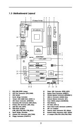
1.3 Motherboard Layout 1 2 34 5 6 17.8cm (7.0 in) PS/2 Mouse PS2_USB_PWR1 1 PS/2 Keyboard Serial Port (COM1) Parallel Port FID4 FID3 FID2 FID1 FID0 CPU_FAN1 1 1 1 1 1 DDR 1 (64/72 bit, ... IDE2 USB 2.0 Ports 28 Line out GGAAMMEE AAUUDDIIOO11 LiLInnineein MMInicicin AUX1 VIA KT400A Chipset 27 CD1 JR1 26 25 JL1 1 AUDIO1 24 DDR400 AGP 8X K7VT4A AGP1 23 LAN PHY 22 AUDIO CODEC PCI 1 Super I/O PCI 2 7 8 9 FSB_SEL0 1 10 21 20 2MB BIOS CMOS Battery PCI 3 USB2.0 5.1CH PCI 4 ATA133 FSB333 11...
1.3 Motherboard Layout 1 2 34 5 6 17.8cm (7.0 in) PS/2 Mouse PS2_USB_PWR1 1 PS/2 Keyboard Serial Port (COM1) Parallel Port FID4 FID3 FID2 FID1 FID0 CPU_FAN1 1 1 1 1 1 DDR 1 (64/72 bit, ... IDE2 USB 2.0 Ports 28 Line out GGAAMMEE AAUUDDIIOO11 LiLInnineein MMInicicin AUX1 VIA KT400A Chipset 27 CD1 JR1 26 25 JL1 1 AUDIO1 24 DDR400 AGP 8X K7VT4A AGP1 23 LAN PHY 22 AUDIO CODEC PCI 1 Super I/O PCI 2 7 8 9 FSB_SEL0 1 10 21 20 2MB BIOS CMOS Battery PCI 3 USB2.0 5.1CH PCI 4 ATA133 FSB333 11...

User Manual
Page 9
... power supply. Make sure to use a grounded wrist strap or touch a safety grounded object before you install motherboard components or change any component. 2. Chapter 2 Installation K7VT4A is detached from the wall socket before touching any motherboard settings. 1. Also remember to unplug the power cord before you handle components. 3. Doing so may cause severe...
... power supply. Make sure to use a grounded wrist strap or touch a safety grounded object before you install motherboard components or change any component. 2. Chapter 2 Installation K7VT4A is detached from the wall socket before touching any motherboard settings. 1. Also remember to unplug the power cord before you handle components. 3. Doing so may cause severe...

User Manual
Page 11
Please make sure to the motherboard and the DIMM if you force the DIMM into the slot until the retaining clips at incorrect orientation. Unlock a DIMM slot by pressing the retaining .... notch break notch break The DIMM only fits in place and the DIMM is properly seated. 11 Step 2. Step 1. Step 3. 2.5 Installation of Memory Modules (DIMM) K7VT4A motherboard provides two 184-pin DDR (Double Data Rate) DIMM slots.
Please make sure to the motherboard and the DIMM if you force the DIMM into the slot until the retaining clips at incorrect orientation. Unlock a DIMM slot by pressing the retaining .... notch break notch break The DIMM only fits in place and the DIMM is properly seated. 11 Step 2. Step 1. Step 3. 2.5 Installation of Memory Modules (DIMM) K7VT4A motherboard provides two 184-pin DDR (Double Data Rate) DIMM slots.

