User Manual
Page 3
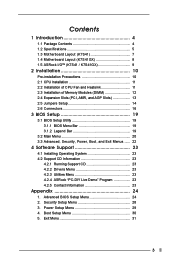
Contents 1 Introduction 4 1.1 Package Contents 4 1.2 Specifications 5 1.3 Motherboard Layout (K7S41 7 1.4 Motherboard Layout (K7S41GX 8 1.5 ASRock I/OTM (K7S41 / K7S41GX 9 2 Installation 10 Pre-installation Precautions 10 2.1 CPU Installation 11 2.2 Installation of CPU Fan and Heatsink ... 23 4.1 Installing Operating System 23 4.2 Support CD Information 23 4.2.1 Running Support CD 23 4.2.2 Drivers Menu 23 4.2.3 Utilities Menu 23 4.2.4 ASRock "PC-DIY Live Demo" Program 23 4.2.5 Contact Information 23 Appendix 24 1. Security Setup Menu 28 3. Exit Menu 31 3 Advanced BIOS ...
Contents 1 Introduction 4 1.1 Package Contents 4 1.2 Specifications 5 1.3 Motherboard Layout (K7S41 7 1.4 Motherboard Layout (K7S41GX 8 1.5 ASRock I/OTM (K7S41 / K7S41GX 9 2 Installation 10 Pre-installation Precautions 10 2.1 CPU Installation 11 2.2 Installation of CPU Fan and Heatsink ... 23 4.1 Installing Operating System 23 4.2 Support CD Information 23 4.2.1 Running Support CD 23 4.2.2 Drivers Menu 23 4.2.3 Utilities Menu 23 4.2.4 ASRock "PC-DIY Live Demo" Program 23 4.2.5 Contact Information 23 Appendix 24 1. Security Setup Menu 28 3. Exit Menu 31 3 Advanced BIOS ...

User Manual
Page 4
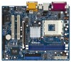
... be available on ASRock website without notice. ASRock website http://www.asrock.com 1.1 Package Contents ASRock K7S41 or K7S41GX Motherboard (Micro ATX Form Factor: 9.6-in x 7.8-in, 24.4 cm x 19.8 cm) ASRock K7S41 / K7S41GX Quick Installation Guide ASRock K7S41 / K7S41GX Support CD One 80-conductor Ultra ATA 66/100/133 IDE Ribbon Cable One Ribbon Cable for purchasing ASRock K7S41 / K7S41GX motherboard, a reliable motherboard produced under ASRock's consistently stringent quality...
... be available on ASRock website without notice. ASRock website http://www.asrock.com 1.1 Package Contents ASRock K7S41 or K7S41GX Motherboard (Micro ATX Form Factor: 9.6-in x 7.8-in, 24.4 cm x 19.8 cm) ASRock K7S41 / K7S41GX Quick Installation Guide ASRock K7S41 / K7S41GX Support CD One 80-conductor Ultra ATA 66/100/133 IDE Ribbon Cable One Ribbon Cable for purchasing ASRock K7S41 / K7S41GX motherboard, a reliable motherboard produced under ASRock's consistently stringent quality...
User Manual
Page 8
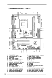
1.4 Motherboard Layout (K7S41GX) 12 3 4 19.8cm (7.8-in) PS2 Mouse PS2_USB_PWR1 1 PS2 Keyboard CPU_FAN1 5 6 24.4cm (9.6-in) ATXPWR1 PARALLEL PORT VGA1 DDR1 (64/72 bit, 184-pin module) DDR2 (... 1 FSB_SEL1 1 FSB_SEL0 SiS 741GX Chipset AGP 8X 1.5V_AGP1 ` ATA133 IDE2 IDE1 AUDIO CODEC AUDIO1 1 JR1 JL1 COM1 1 2MB BIOS PCI 1 Super I/O AMR1 PCI 2 SiS 963L K7S41GX IR1 1 USB45 1 CMOS CLRCMOS1 Battery 5.1CH CLRCMOS2 FLOPPY1 USB 2.0 CHA_FAN1 PWR_LED1 1 PLED PWRBTN SPEAKER1 PANEL 1 1 1 HDLED RST 20 19 18 17 16 15 7 8 9 10 11...
1.4 Motherboard Layout (K7S41GX) 12 3 4 19.8cm (7.8-in) PS2 Mouse PS2_USB_PWR1 1 PS2 Keyboard CPU_FAN1 5 6 24.4cm (9.6-in) ATXPWR1 PARALLEL PORT VGA1 DDR1 (64/72 bit, 184-pin module) DDR2 (... 1 FSB_SEL1 1 FSB_SEL0 SiS 741GX Chipset AGP 8X 1.5V_AGP1 ` ATA133 IDE2 IDE1 AUDIO CODEC AUDIO1 1 JR1 JL1 COM1 1 2MB BIOS PCI 1 Super I/O AMR1 PCI 2 SiS 963L K7S41GX IR1 1 USB45 1 CMOS CLRCMOS1 Battery 5.1CH CLRCMOS2 FLOPPY1 USB 2.0 CHA_FAN1 PWR_LED1 1 PLED PWRBTN SPEAKER1 PANEL 1 1 1 HDLED RST 20 19 18 17 16 15 7 8 9 10 11...

User Manual
Page 10
...x 7.8-in the bag that the motherboard fits into it on the carpet or the like. Hold components by the edges and do so may cause severe damage to the motherboard, peripherals, and/or components. 10 Chapter 2 Installation K7S41 / K7S41GX is detached from the wall socket ...before touching any component. 2. Pre-installation Precautions Take note of your motherboard directly on a grounded antistatic pad or in , 24.4...
...x 7.8-in the bag that the motherboard fits into it on the carpet or the like. Hold components by the edges and do so may cause severe damage to the motherboard, peripherals, and/or components. 10 Chapter 2 Installation K7S41 / K7S41GX is detached from the wall socket ...before touching any component. 2. Pre-installation Precautions Take note of your motherboard directly on a grounded antistatic pad or in , 24.4...

User Manual
Page 12
... at both ends fully snap back in one correct orientation. Step 1. Step 2. 2.3 Installation of Memory Modules (DIMM) K7S41 / K7S41GX motherboard provides two 184-pin DDR (Double Data Rate) DIMM slots. Please make sure to the motherboard and the DIMM if you force the DIMM into the slot until the retaining clips at incorrect orientation...
... at both ends fully snap back in one correct orientation. Step 1. Step 2. 2.3 Installation of Memory Modules (DIMM) K7S41 / K7S41GX motherboard provides two 184-pin DDR (Double Data Rate) DIMM slots. Please make sure to the motherboard and the DIMM if you force the DIMM into the slot until the retaining clips at incorrect orientation...

User Manual
Page 13
...do NOT use . Remove the system unit cover (if your graphics card, please check with v.92 Modem functionality. Step 4. Step 6. The ASRock AGP slot has a special design of clasp that the power supply is switched off or the power cord is already installed in a chassis).... is used to install expansion cards that you start the installation. For the voltage information of your motherboard is unplugged. Fasten the card to use a 3.3V AGP card on K7S41 / K7S41GX motherboard. It may cause permanent damage! Align the card connector with screws. Step 5. Please read the ...
...do NOT use . Remove the system unit cover (if your graphics card, please check with v.92 Modem functionality. Step 4. Step 6. The ASRock AGP slot has a special design of clasp that the power supply is switched off or the power cord is already installed in a chassis).... is used to install expansion cards that you start the installation. For the voltage information of your motherboard is unplugged. Fasten the card to use a 3.3V AGP card on K7S41 / K7S41GX motherboard. It may cause permanent damage! Align the card connector with screws. Step 5. Please read the ...

User Manual
Page 14
...select +5VSB, it requires 2 Amp and higher standby current provided by means of the adjustment of this motherboard is "OPEN". Jumper FSB Select Jumpers (see p.7/p.8 No. 23) JR1 JL1 Note: If the ...jumper cap is "SHORT". JR1(see p.7/p.8 No. 24) JL1(see p.7/p.8 No. 27) Setting K7S41: FSB_SEL2 FSB_SEL1 FSB_SEL0 2_3 1_2 2_3 FSB 200MHz 2_3 FSB_SEL2 2_3 FSB_SEL1 2_3 FSB_SEL0 FSB 266MHz FSB_SEL2... FSB_SEL0 2_3 1_2 1_2 FSB 333MHz 1_2 FSB_SEL2 1_2 FSB_SEL1 1_2 FSB_SEL0 FSB 400MHz K7S41GX: FSB_SEL1 FSB_SEL0 1_2 2_3 FSB 200MHz 2_3 FSB_SEL1 2_3 FSB_SEL0 FSB 266MHz 1_2 FSB_SEL1...
...select +5VSB, it requires 2 Amp and higher standby current provided by means of the adjustment of this motherboard is "OPEN". Jumper FSB Select Jumpers (see p.7/p.8 No. 23) JR1 JL1 Note: If the ...jumper cap is "SHORT". JR1(see p.7/p.8 No. 24) JL1(see p.7/p.8 No. 27) Setting K7S41: FSB_SEL2 FSB_SEL1 FSB_SEL0 2_3 1_2 2_3 FSB 200MHz 2_3 FSB_SEL2 2_3 FSB_SEL1 2_3 FSB_SEL0 FSB 266MHz FSB_SEL2... FSB_SEL0 2_3 1_2 1_2 FSB 333MHz 1_2 FSB_SEL2 1_2 FSB_SEL1 1_2 FSB_SEL0 FSB 400MHz K7S41GX: FSB_SEL1 FSB_SEL0 1_2 2_3 FSB 200MHz 2_3 FSB_SEL1 2_3 FSB_SEL0 FSB 266MHz 1_2 FSB_SEL1...

